EP0057531A2 - Bohrlochpacker - Google Patents
Bohrlochpacker Download PDFInfo
- Publication number
- EP0057531A2 EP0057531A2 EP82300279A EP82300279A EP0057531A2 EP 0057531 A2 EP0057531 A2 EP 0057531A2 EP 82300279 A EP82300279 A EP 82300279A EP 82300279 A EP82300279 A EP 82300279A EP 0057531 A2 EP0057531 A2 EP 0057531A2
- Authority
- EP
- European Patent Office
- Prior art keywords
- collet
- packer
- cam
- sleeve
- packer sleeve
- Prior art date
- Legal status (The legal status is an assumption and is not a legal conclusion. Google has not performed a legal analysis and makes no representation as to the accuracy of the status listed.)
- Ceased
Links
Images
Classifications
-
- F—MECHANICAL ENGINEERING; LIGHTING; HEATING; WEAPONS; BLASTING
- F04—POSITIVE - DISPLACEMENT MACHINES FOR LIQUIDS; PUMPS FOR LIQUIDS OR ELASTIC FLUIDS
- F04D—NON-POSITIVE-DISPLACEMENT PUMPS
- F04D13/00—Pumping installations or systems
- F04D13/02—Units comprising pumps and their driving means
- F04D13/06—Units comprising pumps and their driving means the pump being electrically driven
- F04D13/08—Units comprising pumps and their driving means the pump being electrically driven for submerged use
- F04D13/10—Units comprising pumps and their driving means the pump being electrically driven for submerged use adapted for use in mining bore holes
-
- E—FIXED CONSTRUCTIONS
- E21—EARTH OR ROCK DRILLING; MINING
- E21B—EARTH OR ROCK DRILLING; OBTAINING OIL, GAS, WATER, SOLUBLE OR MELTABLE MATERIALS OR A SLURRY OF MINERALS FROM WELLS
- E21B23/00—Apparatus for displacing, setting, locking, releasing or removing tools, packers or the like in boreholes or wells
- E21B23/01—Apparatus for displacing, setting, locking, releasing or removing tools, packers or the like in boreholes or wells for anchoring the tools or the like
-
- E—FIXED CONSTRUCTIONS
- E21—EARTH OR ROCK DRILLING; MINING
- E21B—EARTH OR ROCK DRILLING; OBTAINING OIL, GAS, WATER, SOLUBLE OR MELTABLE MATERIALS OR A SLURRY OF MINERALS FROM WELLS
- E21B23/00—Apparatus for displacing, setting, locking, releasing or removing tools, packers or the like in boreholes or wells
- E21B23/06—Apparatus for displacing, setting, locking, releasing or removing tools, packers or the like in boreholes or wells for setting packers
-
- E—FIXED CONSTRUCTIONS
- E21—EARTH OR ROCK DRILLING; MINING
- E21B—EARTH OR ROCK DRILLING; OBTAINING OIL, GAS, WATER, SOLUBLE OR MELTABLE MATERIALS OR A SLURRY OF MINERALS FROM WELLS
- E21B33/00—Sealing or packing boreholes or wells
- E21B33/10—Sealing or packing boreholes or wells in the borehole
- E21B33/12—Packers; Plugs
Definitions
- the present invention relates to a well packer, and in particular to a form of well packer designed for use with the bore hole pump disclosed in our British Patent Specification No. 1,567,886. Such a pump is used for pumping water from wells.
- Well packers have been used in the hydrocarbon drilling industry for many years, but are not commonly used in water wells. It is intended that the pump disclosed in our said British Patent Specification No. 1,567,886 should be capable of being positioned not simply at one predetermined location, e.g. the bottom, of a well by attachment of a special casing portion as the bottom member of the bore hole lining pipe, but instead that the pump should be capable of being positioned anywhere in an existing clad well by means of the subsequently installed packer which forms the subject of the present application.
- a well packer comprising a packer sleeve and means to lock the sleeve in a bore hole, characterised in that the packer sleeve has a tapered external surface portion; and in that the means to lock the sleeve comprise an annular collet having an internal surface of a taper able to cooperate with that of the external tapered surface portion of the packer sleeve and having an external surface capable of frictionally engaging a well casing pipe having a diameter larger than the external diameter of the packer sleeve, said collet being resiliently deformable from a larger diameter relaxed configuration to a smaller diameter stressed configuration in which it engages the tapered external surface portion of the packer sleeve; means for holding said collet in said smaller diameter stressed configuration while engaged around the tapered external surface portion of the packer sleeve; and means operable from a remote location to release said collet from its stressed configuration to spring radially outwardly towards its released
- the means for releasing the collet-holding means may, for example, be a cam-operated mechanism responsive to ascent of the packer sleeve up the well, or a mechanism driven by means of a gravity-biased trigger which is held off by supporting the triggering weight until the well packer has reached the desired level in the well whereupon release of the triggering weight operates the collet-releasing trigger action. Any other remotely-operated means may be used.
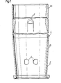
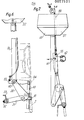
- the packer in accordance with the present invention comprises a packer sleeve 1 of S.G. iron, shown in Figure 1, and a spring steel collet ring 2, shown in Figures 2, 3a and 3b.
- the lower part la of the packer sleeve 1 has a downwardly convergent taper defining an external downwardly convergent tapered surface portion 3 having a taper angle of 4°, and intended to cooperate with the corresponding internal taper surface 4 of the collet ring 2, again having a taper of 4°.
- an outwardly extending flange to retain a collet ring (to be described with reference to Figures 2, 3a and 3b) thereon in the event of premature release of the collet ring.
- the collet ring 2 is held in a stressed condition so as to be confined to contact the tapered external surface portion 3 of the packer sleeve and so as to have no portion of the collet ring extending radially outwardly beyond the vertical projection of the perimeter of the upper cylindrical portion lb of the packer sleeve 1.
- the well packer comprising the packer sleeve 1 with the collet ring 2 thereon will be able to descend freely slidably down the well casing (not shown in Figure 1 but referenced 26 in Figure 4) and the correct level will be reached with the minimum of drag between the well packer and the well casing.
- a collet ring trigger mechanism two embodiments of which are to be described hereinafter with reference to Figures 4 and 5 on the one hand, and to Figures 6, 7 and 8 on the other hand, is operated to release the spring collet ring 2 which snaps radially outwardly to exert a spring clinging action on the internal surface of the well casing.
- the collet ring 2 will withdraw its radially inward tapered surface 4 from the external tapered surface portion 3 of the packer sleeve and it is then necessary to lower the packer sleeve 1 slightly in order to re-engage the tapers whereupon further lowering will simply jam the internal tapered surface 4 of the collet ring 2 firmly into engagement with the external tapered surface portion 3 of the packer sleeve 1 and will lock the packer sleeve 1 in position (the engagement of the tapers being assisted by the fact that the collet ring 2 is sprung into frictional engagement with the well casing).
- the bore hole pump which is to be engaged in the packer ring 1 carries recesses to mate with inwardly extending lugs 5 of the packer sleeve 1, in order to resist the rotation torque of the pump stator when the pump rotor is driven.
- This torque-reaction pipe may either be in the form of a separate delivery pipe which is lowered down the well together with the pump and must therefore be recovered when the pump is pulled out for maintenance or repair, or may comprise a stationary sheath co-axially around and closely spaced from the rotatable drive shaft, again requiring recovery from the well in the event of pump maintenance or repair.
- Using the packer in accordance with the present invention ensures that the pump can be recovered simply by lifting, using the pump rotor drive shaft as the lifting means and can, when desired, be returned to engagement with the lugs 5 of the packer.
- tapered surface 4 of the collet ring 2 and/or the external tapered surface portion 3 is rough-machined to have an undulating surface in the form of a helical screw-thread arrangement so that if the packer sleeve 1 should rotate when the turbine is operated, the fact that the inside of the collet ring 2 has this crude screw-thread on its surface will result in downward movement of the packer sleeve 1 so as more firmly to press the collet ring 2 outwardly into engagement with the interior of the well casing and thereby more securely to anchor the packer sleeve 1 in position.
- the packer sleeve 1 is cast with two holes 6 through which holding fingers (18 in Figure 5) of the collet ring trigger mechanism can protrude radially outwardly so as to engage in corresponding holes 7 ( Figure 2) . in the collet ring 2.
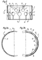
- the finger-receiving holes 7 will, as shown in the relaxed configuration of the collet ring 2 in Figure 2, normally be spaced apart more widely than the corresponding trigger-receiving holes 6 of the lower portion la of the packer sleeve 1. Therefore, in order to permit the collet-holding fingers to engage the finger-receiving holes 7 of the collet ring 2 as they project radially outwardly through the holes 6 of the packer sleeve 1 it is necessary for the collet ring 2 to be compressed circumferentially (using a suitable strap-or band-clamp, not shown) to bring its two end faces 8 at the slit 9a thereof closer together.
- the collet ring 2 is provided with a segment 9 which is welded in place, along an axial line 10 and a circumferential line 11 of the collet ring, so that this segment 9 projects from the left hand side of the longitudinal slit 9a at the upper end of the collet ring 2 to engage slidably with a circumferentially extending wall 13 of an L-shaped recess of the collet ring 2.
- This recess is bounded by the abovementioned circumferential face 13 and an axial face 12 of the collet ring.
- the segment 9 assists in ensuring a sealing action to prevent undue loss of hydrostatic pressure between the well casing on the one hand and the external surface of the packer sleeve 1 on the other hand.
- the purpose of providing a separately formed segment and welding it in place is that this simplifies machining of the spring steel collet ring 2.
- the narrower wall portion at the upper axial end of the collet ring 2 is continuous, except for the slit 9a which is of course bridged by the above-described segment 9.
- the thicker wall portion at the lower axial end of the collet ring 2 is perforated by a series of slots 14 which define between them tongues 15.
- the upper end of each of the slots 14 opens into a circular hole 16 whose radius is at least as great as the width of the slot 14, so that between any two adjacent holes 16 is a bridge 17 of spring steel material which permits the tongue 15 to deflect radially inwardly and outwardly.
- the unbroken upper thin wall section provides a continuous "C" spring which acts like a circlip to hold the exterior of the collet ring 2 in engagement with the interior (26 in Figure 4) of the well casing, while the slotted lower portion defining the separate tongues 15 is nevertheless able to conform to irregular well casings.
- the slots 14 and holes 16 also assist in reducing the stiffness of the collet ring to that of the C spring upper end.
- Any suitable means of releasing the collet ring 2 from its peripherally inwardly stressed configuration to its larger diameter relieved configuration can be provided.
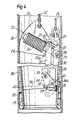
- FIG. 4 shows a side elevational view of the mechanism in its "trigger set” configuration
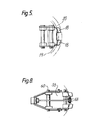
- Figure 5 shows an underneath plan view illustrating the two collet ring-holding fingers 18 and the interior 19 of the lower tapered portion la of the packer sleeve 1 and the internal surfaces 20 of the collet ring 2.
- Figure 4 shows an optional additional line 22 which may, if desired, be used as the lowering line which holds a drive cam plate 23 of the trigger mechanism in its raised "safety" configuration where the end 24 of an arcuate serrated outer surface 25 of the cam plate 23 is just in contact with the interior of the well casing 26 above the packer sleeve 1.
- extra safety is imparted when,during lowering, the weight of the entire assembly is taken by the second lowering line 22 directly operating on the cam plate 23.
- Figure 4 also shows an optional pivotal latch link 27 which, in the configuration shown in Figure 4, holds the cam plate 23 against anti-clockwise movement and clear of the well casing 26. It is this anti-clockwise movement of the cam plate 23 which will be necessary in order to trigger the release of the collet ring-holding fingers 18.
- the latch link can be released by an upward pull (using the line 22 connected to the hole at the free end of the latch link 27 or any other suitable means) from the surface at the top of the well.
- the cam plate 23 is slidable with respect to a mounting arm 28 which itself is mounted on a pivot 29 with respect to a pair of main links 30 only one of which can be seen in Figure 4.
- a pair of operating links 32 is pivoted at its top end (on a pin 31) to the cam plate 23 and has, at its bottom end, a pivot pin 33 articulating it to a pair of cam links 34 which has another pivot 35 articulating it to the pair of main links 30.
- the sliding movement of the cam plate 23 with respect to its mounting arm 28 is biased by means of a helical compression spring 36 pressing the cam plate 23 radially outwardly with respect to the support arm 28 until a stop screw 37 on a stop plate portion 23a of the cam plate 23 is in engagement with a shoulder on the mounting arm 28, this shoulder also providing an abutment for one end of the compression spring 36. Adjustment of the screw 37 changes the radially outward position of the travel of the stop plate 23 along the mounting arm 28.
- the cam links 34 are each in the form of a cam which has a toe 34a which, in the "trigger set” configuration of Figure 4, lies clear of the internal surface 19 ( Figure 5) of the packer sleeve tapered portion la.
- lowering of the pivot pin 33 due to anti-clockwise rotation of the cam plate 23 and its mounting arm 28, will rotate the cam links 34 in the anti-clockwise direction to bring the toes 34ja into engagement with the internal surface 19 of the packer sleeve tapered portion la and further rotation will pull the pivot pin 35 inwardly towards the centre of curvature of the packer sleeve 1, withdrawing the fingers 18 from the finger-receiving holes 7 of the collet ring 2 until they have retracted to release the collet ring 2 to allow it to spring radially outwardly into engagement with the well casing 26.
- the triggering mechanism is provided with a safety link 38 which is pivoted at 39 to the cam links 34 and has an outer end shoe 40 normally engaging the interior of the opposite side of the interior of the packer sleeve portion la to hold the collet ring-holding fingers 18 firmly in their receiving holes 6 of the packer sleeve 1.
- Initial rotation of the cam links 34 drives a stud 41 of the safety link 38 downwardly to release the end shoe 40 from its position of engagement with the interior of the packer sleeve 1 so that only after the drive cam plate 23 has begun its anti-clockwise rotation is the safety link 38 disengaged. This now frees the fingers 18 to be retracted upon further rotation of the cam links 34.
- the cam surface 25 of the drive cam plate 23 is serrated, as described above, and has a varying radius of curvature from the portion 24 where the radius of curvature is tightest to the opposite end of the cam surface 25 where the curvature of the cam surface is greatest. This ensures a progressively increasing engagement action of the cam surface 25 with the interior of the well casing 26 as the entire triggering mechanism is lifted using line 21 after off-loading of the line 22 (if the line 22 has been fitted) or after release of the latch link 27 if this has instead been used as the safety mechanism.
- the gravity-triggered form of holding mechanism shown in Figures 6, 7 and 8 has a similar cam link pair 50 and safety link 51, except that in this case the safety link 51 is provided with an adjustable end comprising a removable threaded stud 52 and an exchangeable bracket 53 so that the end of the safety link 51 can be adjusted to suit different diameters of packer sleeve 1.
- Figure 6 is also interesting in that it shows an alternative form of packer sleeve 54 which provides the seating for a 6 inch (150 mm) pump but has its external tapered surfaces matched to an 8 inch (204 mm) well casing diameter.
- the latch link 55 is at the bottom end of the main links 56 and is directly connected to a release line B.
- the top end of the pair of main links 56 carries the gravity-triggering weight 57 which has a passage 58 to allow the latch release line B to pass therethrough.
- a main lowering line A ( Figure 7), is attached to an eyebolt 59 at the top of the triggering weight 57 and is the line which will normally be used for lowering the assembly of the packer sleeve 1, the collet ring 2 and the collet ring-holding mechanism down the well casing.
- Figure 6 shows, in broken lines, the position of the collet ring 2 at the bottom (the narrowest diameter end) of the tapered external surface portion of the packer sleeve 54.
- a latch safety clip spring 62 is provided to hold the latch 55 securely in the "trigger set” configuration until the packer sleeve 1, collet ring 2 and collet ring-holding mechanism have been correctly positioned in the top of the bore hole and the lines A and B are in the correct configuration to begin lowering.
- a suitable safety clip is also envisaged for use with the latch link 27 of Figure 4, and the latch pin 31.
- tensioning clamp (not shown) which is a band-clamp or strap-clamp placed around the collet ring 2 once the collet ring has itself been placed in the position shown in Figure 6, and then tightened in order to pull the collet ring 2 to its smaller diameter configuration in which the two finger-receiving holes 7 are both in register with the corresponding finger-receiving holes 6 of the packer sleeve 1.
- the trigger weight 57 is lifted to the Figure 6 configuration to allow the latch link 55 to be positioned with its recess 61 encompassing the pivot pin 60, and then the safety link 51 is pivoted in the clockwise direction to bring its end into engagement with the interior of the packer sleeve 1 opposite the two holes 6 thereof.
- the latch spring 62 must be placed in position so that the entire assembly in its "trigger set” configuration can then be transported to the well head and connected to the appropriate lifting lines ready for insertion into the well head and removal of the latch safety clip spring 62 to arm the mechanism.
- a particularly convenient feature of the embodiment shown in Figures 6 to 8 is that the diameter of the triggering weight 57 is substantially the same as that of the well casing so that, after the cam links 50 and the safety link 55 have dropped into the "triggered position" shown in Figure 7, the radially outer portion of the frusto-conical lower surface 65 of the triggering weight 57 can be used to hammer home the packer sleeve 1 onto its collet ring 2 by repeatedly lifting the triggering weight 57 clear of the packer sleeve 54 and then dropping it onto the top of the sleeve. This will ensure a tight fit of the packer sleeve'1 in the well casing before the collet ring-holding mechanism is recovered and the pump lowered into position.
- the combination of the packer sleeve 1 with its sprung collet ring 2 provides a particularly convenient form of well packer intended for supporting a bore hole pump where the external diameter of the bore hole pump is not much less than the internal diameter of the well casing.
- the combination of the thin- walled packer sleeve 1, together with its sprung collet ring 2 is devoid of any collet-releasing linkage since this is all recovered by pulling to the surface using line 21 of Figures 4 and 5 or using line B of Figure 7.
- the packer sleeve 1 has a small diametral thickness to allow it to fit into the well casing 26 and to offer the minimum obstruction to the useful cross-sectional area in the well casing
- the special design of the collet ring 2 as described with reference to Figures 2, 3a and 3b by which it has a series of tongues 15 at its lower part and a continuous "C" spring at its upper part allows it to accommodate a wide variation of pipe diameters (because of the wide tolerance on pipe manufacture) and also a wide variation of collet ring diameter as the collet ring travels up the tapered exterior of the lower part of the packer sleeve 1 upon engagement.
- the taper angle has been quoted in the above description for the taper angle.
- any suitable taper angle can be used.
- the taper be in the range from 2° to 5°.
- the pump casing is provided with its own seal for example an O-ring seal to ensure that no such loss of pumped fluid can occur through a gap between the exterior of the pump casing and the interior surface of the seating defined by the packer sleeve 1.
Landscapes
- Engineering & Computer Science (AREA)
- Mining & Mineral Resources (AREA)
- Geology (AREA)
- Life Sciences & Earth Sciences (AREA)
- Environmental & Geological Engineering (AREA)
- Fluid Mechanics (AREA)
- Physics & Mathematics (AREA)
- General Life Sciences & Earth Sciences (AREA)
- Geochemistry & Mineralogy (AREA)
- Mechanical Engineering (AREA)
- General Engineering & Computer Science (AREA)
- Consolidation Of Soil By Introduction Of Solidifying Substances Into Soil (AREA)
- Piles And Underground Anchors (AREA)
- Structures Of Non-Positive Displacement Pumps (AREA)
Applications Claiming Priority (2)
| Application Number | Priority Date | Filing Date | Title |
|---|---|---|---|
| GB8102742 | 1981-01-29 | ||
| GB8102742A GB2092204B (en) | 1981-01-29 | 1981-01-29 | Well casing anchor |
Publications (2)
| Publication Number | Publication Date |
|---|---|
| EP0057531A2 true EP0057531A2 (de) | 1982-08-11 |
| EP0057531A3 EP0057531A3 (de) | 1982-08-25 |
Family
ID=10519324
Family Applications (1)
| Application Number | Title | Priority Date | Filing Date |
|---|---|---|---|
| EP82300279A Ceased EP0057531A3 (de) | 1981-01-29 | 1982-01-19 | Bohrlochpacker |
Country Status (5)
| Country | Link |
|---|---|
| US (1) | US4379561A (de) |
| EP (1) | EP0057531A3 (de) |
| AU (1) | AU542723B2 (de) |
| GB (1) | GB2092204B (de) |
| ZA (1) | ZA82313B (de) |
Cited By (1)
| Publication number | Priority date | Publication date | Assignee | Title |
|---|---|---|---|---|
| CN115788353A (zh) * | 2023-02-07 | 2023-03-14 | 山东华冠能源技术有限公司 | 套管外封隔器 |
Families Citing this family (4)
| Publication number | Priority date | Publication date | Assignee | Title |
|---|---|---|---|---|
| US4901794A (en) * | 1989-01-23 | 1990-02-20 | Baker Hughes Incorporated | Subterranean well anchoring apparatus |
| US9816329B2 (en) | 2014-08-12 | 2017-11-14 | Baker Huges, A Ge Company, Llc | Quick connection arrangements with locking mechanisms |
| US12252952B2 (en) * | 2023-04-28 | 2025-03-18 | Halliburton Energy Services, Inc. | Expandable metal for non-compliant areas between screens |
| CN116752933B (zh) * | 2023-08-22 | 2023-11-03 | 大庆市璞庆钻采设备制造有限公司 | 一种触发解封的可捞桥塞 |
Family Cites Families (15)
| Publication number | Priority date | Publication date | Assignee | Title |
|---|---|---|---|---|
| CA676042A (en) * | 1963-12-17 | V. Fredd John | Methods and means for operating a well | |
| US1501957A (en) * | 1919-11-28 | 1924-07-22 | Oil Well Supply Co | Disk or retaining means for well packers |
| US1380182A (en) * | 1920-05-17 | 1921-05-31 | Robert J Bigelow | Well-liner clamp |
| US1604771A (en) * | 1925-08-10 | 1926-10-26 | Harrison M Gill | Liner adapter for well casings |
| US2335025A (en) * | 1941-10-27 | 1943-11-23 | Frank A Reed | Oil well packer |
| US2692648A (en) * | 1952-01-21 | 1954-10-26 | Sells Simmons Hydrostatic Bail | Well tubing anchor |
| GB893623A (en) * | 1960-03-08 | 1962-04-11 | Us Industries Inc | Flow control apparatus |
| US3420308A (en) * | 1967-08-16 | 1969-01-07 | Fmc Corp | Well casing hanger |
| US3891031A (en) * | 1974-02-04 | 1975-06-24 | Carlos Mayer Ortiz | Sealing means for deep-well |
| CA1057092A (en) * | 1975-11-11 | 1979-06-26 | Bergwerksverband G.M.B.H. | Tubular one-way closure for injecting a material into a hole |
| US4142371A (en) * | 1977-08-08 | 1979-03-06 | Regal Tool & Rubber Co., Inc. | Removable closure apparatus for hollow columnar members |
| GB1567886A (en) * | 1978-02-23 | 1980-05-21 | Mono Pumps Ltd | Bore hole pumps |
| SU729632A1 (ru) | 1978-05-05 | 1980-04-25 | Предприятие П/Я М-5308 | Способ изготовлени матриц дл запоминающих блоков |
| GB2029500B (en) * | 1978-08-29 | 1982-09-22 | Hayward Tyler Ltd | Means for gripping the inside surface of a pipe |
| US4212352A (en) * | 1979-01-08 | 1980-07-15 | Dresser Industries, Inc. | Gripping member for well tools |
-
1981
- 1981-01-29 GB GB8102742A patent/GB2092204B/en not_active Expired
-
1982
- 1982-01-18 ZA ZA82313A patent/ZA82313B/xx unknown
- 1982-01-19 EP EP82300279A patent/EP0057531A3/de not_active Ceased
- 1982-01-21 AU AU79693/82A patent/AU542723B2/en not_active Withdrawn - After Issue
- 1982-01-28 US US06/343,568 patent/US4379561A/en not_active Expired - Fee Related
Cited By (1)
| Publication number | Priority date | Publication date | Assignee | Title |
|---|---|---|---|---|
| CN115788353A (zh) * | 2023-02-07 | 2023-03-14 | 山东华冠能源技术有限公司 | 套管外封隔器 |
Also Published As
| Publication number | Publication date |
|---|---|
| AU542723B2 (en) | 1985-03-07 |
| ZA82313B (en) | 1982-11-24 |
| GB2092204A (en) | 1982-08-11 |
| US4379561A (en) | 1983-04-12 |
| AU7969382A (en) | 1982-08-05 |
| EP0057531A3 (de) | 1982-08-25 |
| GB2092204B (en) | 1984-08-30 |
Similar Documents
| Publication | Publication Date | Title |
|---|---|---|
| US4811785A (en) | No-turn tool | |
| US3977473A (en) | Well tubing anchor with automatic delay and method of installation in a well | |
| US5107931A (en) | Temporary abandonment cap and tool | |
| US6302217B1 (en) | Extreme service packer having slip actuated debris barrier | |
| US4830103A (en) | Setting tool for mechanical packer | |
| US11578553B2 (en) | Tubing hanger assembly with adjustable load nut | |
| US8136604B2 (en) | Wireline run fracture isolation sleeve and plug and method of operating same | |
| NO302969B1 (no) | Rörhengeranordning og fremgangsmåte for installering av et forlengingsrör i en brönn | |
| US5638903A (en) | Adjustable mandrel hanger system | |
| JPS6320999B2 (de) | ||
| EP2514912A1 (de) | Glattrohrsperre für eine rückziehbare Aufnahmeverlängerung | |
| NO146248B (no) | Anordning for loesbart feste av en gjenstand, f.eks. en borehullsementeringsplugg til en roerformet kapsling | |
| JPS5833359B2 (ja) | イノパツカ | |
| JPH0390792A (ja) | 油井装置 | |
| US4901793A (en) | No-turn tool for a pumping system | |
| GB2269414A (en) | Adjustable mandrel casing hanger | |
| US4379561A (en) | Well packer | |
| US20130068466A1 (en) | Latching mechanism with adjustable preload | |
| US20040108739A1 (en) | Whipstock retrieving overshot | |
| US4706745A (en) | Lock-down releasing spear assembly | |
| US4340116A (en) | Slip deployment mechanism | |
| EP0379376A1 (de) | Hängevorrichtung | |
| GB2087957A (en) | Subsurface control valve apparatus ia-c | |
| US4735268A (en) | Mechanical setting tool | |
| JPS6245393B2 (de) |
Legal Events
| Date | Code | Title | Description |
|---|---|---|---|
| PUAI | Public reference made under article 153(3) epc to a published international application that has entered the european phase |
Free format text: ORIGINAL CODE: 0009012 |
|
| PUAL | Search report despatched |
Free format text: ORIGINAL CODE: 0009013 |
|
| AK | Designated contracting states |
Designated state(s): AT BE CH DE FR IT LU NL SE |
|
| AK | Designated contracting states |
Designated state(s): AT BE CH DE FR IT LU NL SE |
|
| 17P | Request for examination filed |
Effective date: 19821208 |
|
| STAA | Information on the status of an ep patent application or granted ep patent |
Free format text: STATUS: THE APPLICATION HAS BEEN REFUSED |
|
| 18R | Application refused |
Effective date: 19841126 |
|
| RIN1 | Information on inventor provided before grant (corrected) |
Inventor name: NELSON, HUGH DOUGLAS |