EP0057482B1 - Method and device for producing a series of carrying boards to be used in the production of bricks - Google Patents
Method and device for producing a series of carrying boards to be used in the production of bricks Download PDFInfo
- Publication number
- EP0057482B1 EP0057482B1 EP82200081A EP82200081A EP0057482B1 EP 0057482 B1 EP0057482 B1 EP 0057482B1 EP 82200081 A EP82200081 A EP 82200081A EP 82200081 A EP82200081 A EP 82200081A EP 0057482 B1 EP0057482 B1 EP 0057482B1
- Authority
- EP
- European Patent Office
- Prior art keywords
- mould
- series
- moulds
- polyethene
- carrier plates
- Prior art date
- Legal status (The legal status is an assumption and is not a legal conclusion. Google has not performed a legal analysis and makes no representation as to the accuracy of the status listed.)
- Expired
Links
- 238000004519 manufacturing process Methods 0.000 title claims description 10
- 238000000034 method Methods 0.000 title claims description 10
- 239000011449 brick Substances 0.000 title claims description 9
- 229920000573 polyethylene Polymers 0.000 claims description 10
- 238000001746 injection moulding Methods 0.000 claims description 7
- 229920001903 high density polyethylene Polymers 0.000 claims description 6
- 238000007789 sealing Methods 0.000 claims description 6
- 229920005989 resin Polymers 0.000 claims description 4
- 239000011347 resin Substances 0.000 claims description 4
- 229920003002 synthetic resin Polymers 0.000 claims description 4
- 239000000057 synthetic resin Substances 0.000 claims description 4
- 238000003825 pressing Methods 0.000 claims description 2
- 238000009718 spray deposition Methods 0.000 claims description 2
- 239000012779 reinforcing material Substances 0.000 claims 1
- 239000011248 coating agent Substances 0.000 description 13
- 238000000576 coating method Methods 0.000 description 13
- 238000002347 injection Methods 0.000 description 5
- 239000007924 injection Substances 0.000 description 5
- 229920000728 polyester Polymers 0.000 description 5
- 229920001225 polyester resin Polymers 0.000 description 5
- 239000004645 polyester resin Substances 0.000 description 5
- 230000003014 reinforcing effect Effects 0.000 description 5
- 101100043656 Caenorhabditis elegans stdh-4 gene Proteins 0.000 description 3
- 239000007788 liquid Substances 0.000 description 3
- 239000000463 material Substances 0.000 description 3
- 229920002379 silicone rubber Polymers 0.000 description 2
- 239000003795 chemical substances by application Substances 0.000 description 1
- 230000000295 complement effect Effects 0.000 description 1
- 238000005429 filling process Methods 0.000 description 1
- 239000003365 glass fiber Substances 0.000 description 1
- 238000010438 heat treatment Methods 0.000 description 1
- 239000004570 mortar (masonry) Substances 0.000 description 1
- 238000000465 moulding Methods 0.000 description 1
- 239000011120 plywood Substances 0.000 description 1
- 230000002787 reinforcement Effects 0.000 description 1
- 238000007493 shaping process Methods 0.000 description 1
- 238000006467 substitution reaction Methods 0.000 description 1
- 238000013022 venting Methods 0.000 description 1
- 238000003466 welding Methods 0.000 description 1
- 239000002023 wood Substances 0.000 description 1
Images

Classifications
-
- B—PERFORMING OPERATIONS; TRANSPORTING
- B65—CONVEYING; PACKING; STORING; HANDLING THIN OR FILAMENTARY MATERIAL
- B65D—CONTAINERS FOR STORAGE OR TRANSPORT OF ARTICLES OR MATERIALS, e.g. BAGS, BARRELS, BOTTLES, BOXES, CANS, CARTONS, CRATES, DRUMS, JARS, TANKS, HOPPERS, FORWARDING CONTAINERS; ACCESSORIES, CLOSURES, OR FITTINGS THEREFOR; PACKAGING ELEMENTS; PACKAGES
- B65D19/00—Pallets or like platforms, with or without side walls, for supporting loads to be lifted or lowered
- B65D19/0002—Platforms, i.e. load supporting devices without provision for handling by a forklift
-
- B—PERFORMING OPERATIONS; TRANSPORTING
- B28—WORKING CEMENT, CLAY, OR STONE
- B28B—SHAPING CLAY OR OTHER CERAMIC COMPOSITIONS; SHAPING SLAG; SHAPING MIXTURES CONTAINING CEMENTITIOUS MATERIAL, e.g. PLASTER
- B28B7/00—Moulds; Cores; Mandrels
- B28B7/0029—Moulds or moulding surfaces not covered by B28B7/0058 - B28B7/36 and B28B7/40 - B28B7/465, e.g. moulds assembled from several parts
- B28B7/0055—Mould pallets; Mould panels
-
- B—PERFORMING OPERATIONS; TRANSPORTING
- B29—WORKING OF PLASTICS; WORKING OF SUBSTANCES IN A PLASTIC STATE IN GENERAL
- B29C—SHAPING OR JOINING OF PLASTICS; SHAPING OF MATERIAL IN A PLASTIC STATE, NOT OTHERWISE PROVIDED FOR; AFTER-TREATMENT OF THE SHAPED PRODUCTS, e.g. REPAIRING
- B29C33/00—Moulds or cores; Details thereof or accessories therefor
- B29C33/30—Mounting, exchanging or centering
- B29C33/301—Modular mould systems [MMS], i.e. moulds built up by stacking mould elements, e.g. plates, blocks, rods
-
- B—PERFORMING OPERATIONS; TRANSPORTING
- B29—WORKING OF PLASTICS; WORKING OF SUBSTANCES IN A PLASTIC STATE IN GENERAL
- B29C—SHAPING OR JOINING OF PLASTICS; SHAPING OF MATERIAL IN A PLASTIC STATE, NOT OTHERWISE PROVIDED FOR; AFTER-TREATMENT OF THE SHAPED PRODUCTS, e.g. REPAIRING
- B29C33/00—Moulds or cores; Details thereof or accessories therefor
- B29C33/34—Moulds or cores; Details thereof or accessories therefor movable, e.g. to or from the moulding station
- B29C33/36—Moulds or cores; Details thereof or accessories therefor movable, e.g. to or from the moulding station continuously movable in one direction, e.g. in a closed circuit
-
- B—PERFORMING OPERATIONS; TRANSPORTING
- B29—WORKING OF PLASTICS; WORKING OF SUBSTANCES IN A PLASTIC STATE IN GENERAL
- B29C—SHAPING OR JOINING OF PLASTICS; SHAPING OF MATERIAL IN A PLASTIC STATE, NOT OTHERWISE PROVIDED FOR; AFTER-TREATMENT OF THE SHAPED PRODUCTS, e.g. REPAIRING
- B29C39/00—Shaping by casting, i.e. introducing the moulding material into a mould or between confining surfaces without significant moulding pressure; Apparatus therefor
- B29C39/22—Component parts, details or accessories; Auxiliary operations
- B29C39/26—Moulds or cores
- B29C39/265—Moulds or cores comprising two large plates positioned at a small distance from each other, e.g. for making panels
-
- B—PERFORMING OPERATIONS; TRANSPORTING
- B29—WORKING OF PLASTICS; WORKING OF SUBSTANCES IN A PLASTIC STATE IN GENERAL
- B29C—SHAPING OR JOINING OF PLASTICS; SHAPING OF MATERIAL IN A PLASTIC STATE, NOT OTHERWISE PROVIDED FOR; AFTER-TREATMENT OF THE SHAPED PRODUCTS, e.g. REPAIRING
- B29C70/00—Shaping composites, i.e. plastics material comprising reinforcements, fillers or preformed parts, e.g. inserts
- B29C70/68—Shaping composites, i.e. plastics material comprising reinforcements, fillers or preformed parts, e.g. inserts by incorporating or moulding on preformed parts, e.g. inserts or layers, e.g. foam blocks
Definitions
- planks 7 are coupled with one another by corresponding, complementary profiles.
- a first coating 10 of reinforced polyester is applied around the assembled planks.
- a second coating 11 is applied around this coating 10.
- the coating 10 and 11 together constitute the covering coating 9.
- the mould halves 23 and 31 comprise high frame fillets 55 and low frame fillets 58 respectively.
- Each mould half 23, 31 comprises a plate 52 of hard polyethene, viz. high density polyethene, which is known by the indication PE50 and also known by the trade name hostaleen GM5010 or GM5010T 2 .
- the edges 54 of the plate 52 are intimately fitted in a groove 53 of the frame fillets 55, 58 of the same material and are secured to the frame fillets 55 my means of fastening means formed by screws 56 directed transversely to the groove 53.
Landscapes
- Engineering & Computer Science (AREA)
- Mechanical Engineering (AREA)
- Chemical & Material Sciences (AREA)
- Manufacturing & Machinery (AREA)
- Ceramic Engineering (AREA)
- Composite Materials (AREA)
- Moulds For Moulding Plastics Or The Like (AREA)
- Laminated Bodies (AREA)
- Road Paving Structures (AREA)
- Pallets (AREA)
Description
- A carrying board formed, for example, by a wooden or plywood plate is known to be used in mass production on line of, for example, concrete products such as paving stones, curb stones, wall blocks and the like. In this process a templet is lowered onto the supported board and subsequently filled with mortar, after which the templet is removed, leaving behind the moulded product to cure. At the end of the production line the products lying at intervals on the board are shifted towards one another by clamping jaws and removed, whilst being clamped, from the board. Mechanical damage will thus soon arise, for example, identations due to pressing down the templets and heavy wear due to shifting together the moulded products prior to removal. As a result of such mechanical damage the lifetime of such a known board is limited.
- The invention relates to and provides in the first place a method of producing carrying boards which are resistant for a long lifetime. The method of the invention is described in claim 1.
- According to this invented method the carrying boards can be produced in an economic way. Although the injection moulding process for an article having such a great surface as a carrying board requires very strong closing means, the proposed method is economic thanks to using strong closing means which are common for a series of moulds. Also a single injection device is used for said series of moulds. It is noted that an injection moulding process for simultaneously moudling a plurality of articles with a battery of moulds is generally known per se e.g. from US-A-2 992 455 and US-A-3 659 997, wherein the mould cavities are simultaneously filled from a common nozzle of an injection moulding device through a common and/or branched injection channel. These known devices are not used for producing brick carrying boards.
- NL-A-7116038 discloses a method and device for producing panels in which a body is coated with a layer of resin. It does neither disclose the production of brick carrying boards having bodies composed of interconnected wooden elements, nor the use of battery moulds with common closing means and common injection device with movable injection nozzle.
- FR-A-1471971 discloses a brick carrying board, having a wooden body consisting of a single beam. This beam is enveloped by a layer of reinforcement and a layer of resin. It does not disclose the method of coating in a mould, nor the use of a battery of moulds.
- FR-A-2098224 discloses the coating of a wooden body in an open mould. It does not disclose the coating by an injection moulding process, nor the production of a brick carrying board or the use of a battery-moulding device.
- The invention also relates to and provides a device for producing carrying boards for bricks as described in claim 2.
- With the method and device of present invention it is also possible to renovate carrying boards, which has the advantage that the brick producer is not confronted with the problem of removing carrying boards having become unusable.
- In order to provide a wide space between the two mould parts of a mould, the carrier plates of the device are preferably movable over a long path. In order to reduce the length of the closing means, e.g. hydraulic cylinders, the closing means push away from displaceable supporting means which are lockable in a closing position.
- Shaping polyester resin in a mould has the disadvantage that polyester resin tends to stick to the walls of the mould cavity. Therefore, the mould cavity is greased with a detacking agent. This is a circuitous job and when it is carelessly carried out, the sticking problem does nevertheless occur. This sticking problem is solved in the device of claims 4-6.
- Since this material does not readily adhere to other mould parts, a preferred embodiment of a device according to the invention is characterized in that the edges of at least one polyethene plate are inserted into a groove of frame fillets and secured to the frame fillets by means of fastening means transversely directed to the groove.
- A satisfactory seal between frame fillet and plate is obtained when at least one plate of polyethene, preferably high density polyethene is secured to a frame fillet and the frame fillet is in sealing relationship with the plate by means of a tag provided on the frame fillet.
- The above mentioned and further features of the invention will be described with reference to a drawing of some examples and preferred embodiments. The drawing shows in
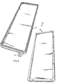
- Figure 1 a perspective view, partly broken away, of an embodiment of a carrying board in accordance with the invention,
- Figure 2 an enlarged cross-sectional view taken on the line II-II in Figure 1,
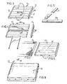
- Figure 3 a perspective view of a known, damaged carrying board,
- Figure 4 a perspective view of the carrying board of Figure 3 in a partly dismounted state,
- Figure 5 substitution of parts for the board of Figure 4,
- Figure 6 a perspective view of the connected elements of the body for a renovated carrying board,
- Figure 7 a schematic, perspective view of a reinforcing mat to cover the body of Figure 6,
- Figure 8 a schematic, perspective view of a mould for applying a coating,
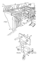
- Figure 9 a device for applying a coating to carrying boards in accordance with the invention,
- Figure 10 a carriage to be used in the device of Figure 9,
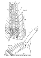
- Figure 11 a perspective view of the two mould halves of a mould employed in the device of Figure 9,
- Figure 12 an enlarged sectional view of the mould of Figure 11 taken on the line XII-XII in Figure 9,
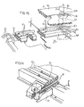
- Figure 13 a detail XIII of Figure 12 during the manufacture thereof,
- Figure 14 and 15 an enlarged, perspective view of details XIV and XV respectively of Figure 9.
- Figure 1 shows an embodiment of a carrying board in accordance with the invention. The carrying board 6 consists of a wooden body constituted by a number of
planks 7, which are coupled at the head ends by a U-shaped profile beam 8 so that the corresponding surfaces smoothly join one another. The U-shaped beam 8 is secured in place by elements (not shown), for example, wood screws. The carrying board is completely enveloped by acoating 9. - It is clearly apparent from Figure 2 that the
planks 7 are coupled with one another by corresponding, complementary profiles. In this embodiment afirst coating 10 of reinforced polyester is applied around the assembled planks. Around thiscoating 10 is applied a second coating 11. Thecoating 10 and 11 together constitute the covering coating 9. - Figure 3 shows a known carrying
board 12 in accordance with the prior art. This carrying board comprisesplanks 13, one of which, designated byreference numeral 13', has a hole. There are furthermore a plurality of less serious damagedareas 14. This damage is caused by scratches and/or identations. The carryingboard 12 is provided at the head edges withU-section beams 15, which are fastened to theplanks 13 by means of screws 16. The connection of theplanks 13 with one another are furthermore established by means ofbolts 17 passed through holes previously provided in theplanks 13 and co-operating with nuts 18. The nuts and bolt heads are countersunk in the side planks. - Figure 4 illustrates how the plank 13' is removed after the removal of one of the
U-section beams 15 and will be replaced by a new, at least furtherusable plank 28. - After complete assembly of the repaired board 12 a reinforcing
mat 19 is arranged around theboard 12 as is shown in Figure 7. This reinforcingmat 19 may consist of non-cured polyester resin including glass fibres. Subsequently the carryingboard 12 provided with the reinforcingmat 19 is placed in amould 20 schematically shown in Figure 8, after which by opening a flap 21 a polyester resin is introduced by pressure through aninlet 22. After the polyester resin has cured the carrying board is ready for use. - The
device 30 for coating carryingboards polyester layer 9 comprises aframe 29 having two horizontal guide members (rails) 28, to which a series of hangingplates 27 withrollers 26 are suspended so as to be mobile between a stationary supportingplate 25 and adisplaceable supporting plate 24. To the hangingplates 27 can be individually fastened mould halves 23 and 31 by means ofscrews 32. - The mould halves 23 and 31 together form a
mould cavity 33 adapted to receive a carryingboard 34. The carryingboards 34 to be coated or renovated are each supplied for example, bycarriages 35 to which they are suspended, for example, by means of suckingcups 36 in a vertical plane inclined at an angle a to the horizon 38. By means of alifting cylinder 37 they are suspended to acarriage 35 at the selected level corresponding with the level of themould cavity 33 concerned. - The hanging plates are provided with heating means, for example steam pipes, connected by means of
hoses 40 with asteam feeding conduit 41. The supportingplate 24 can be bolted by means oflock bolts 42 to floor cylinders 43 and rail holes 44 so that the hangingplates 27 with themoulds 45 arranged between them and filled with carryingboards 34 can be joined, for example, by hand to form a continuous assembly, after which by energizing closing means short hydraulic rams) 46 the required high closing pressure can be obtained. - The
device 30 comprises apolyester injection device 47 known per se being displaceable along rails 80, which can be connected for supplying liquid polyester at high pressure, with eachinlet 51 of twomoulds 45 throughheated ducts 49 and a connectinghead 50 including a closing member 48. - The mould halves 23 and 31 comprise
high frame fillets 55 andlow frame fillets 58 respectively. Eachmould half plate 52 of hard polyethene, viz. high density polyethene, which is known by the indication PE50 and also known by the trade name hostaleen GM5010 or GM5010T2. The edges 54 of theplate 52 are intimately fitted in agroove 53 of theframe fillets frame fillets 55 my means of fastening means formed byscrews 56 directed transversely to thegroove 53. - On the outer side of the
mould 45, adjacent thegroove 53, a sealing strip 77 of silicon rubber is arranged in agroove 59, in which it is fastened by a thermal weld. Thefillets 55 of themould half 23 have furthermore twogrooves 60 holding sealing strips 61 of silicon rubber, which bulge out when the mould is not closed and join theclosing face 62 of themould half 31 in the closed state. - The
frame fillets 55 are interconnected by means ofelbow pieces 63 and connecting pins 64. Likewise theframe fillets 58 are interconnected by means ofelbow pieces 65 and connecting pins 64. - The
inlet piece 51 provided at thelower corner 66 has a tapering spray-castingentrance 67. The connecting piece of the resultant product can thus be readily removed. Complete filling of themould 45 is ensured by the sloping diposition of themould 45, the synthetic resin feed on the lower side and venting on the top side 68 (Figure 15). Thefillet 58 has atransverse channel 69 connecting themould cavity 33 with achannel 70 formed by a depression a of 0.5 mm between the sealing strips 61 and communicating with an outlet 71. As soon as liquid synthetic resin emerges from the outlet 71 the filling process is stopped by closing the closing member 48. - Owing to the
narrow channel 70 and the resultant flow resistance themould cavity 33 can be filled with high pressure. - In manufacturing and particularly in renovating carrying
boards 34 they are first enveloped in one ormore mats 76 of reinforcing fibres and placed in amould half 23 in the deepest part of the openedmould cavity 33 and themoulds 45 are closed at high pressure and individually filled through the opened closing member 48 so that the liquid polyester envelops the carryingboards 34 on all sides and penetrates into all orifices and cracks thereof. Owing to the use of the selected material bounding themould cavity 33 and owing to the smooth transitional area of thetag 57 each ready carrying board can be readily removed from the opened mould. Owing to the internal pressure of themould cavity 33 thetag 57 engages theplate 52 in sealing relationship. - in the manufacture of the mould the
tag 57 is moved, for example, by means of a direction pointer and formed on theplate 52 by a hot-air welding tool 74. - It should be noted that polyethene and particularly hard polyethene, especially the mentioned high density polyethene is useful not only for carrying board moulds but also for coating mould cavities for other, particularly, bulky products such as surf boards and the like.
Claims (10)
Priority Applications (2)
| Application Number | Priority Date | Filing Date | Title |
|---|---|---|---|
| AT82200081T ATE7129T1 (en) | 1981-02-04 | 1982-01-22 | METHOD AND DEVICE FOR PRODUCTION OF A SERIES OF PALLETS FOR BRICK PRODUCTION. |
| AU80083/82A AU553363B2 (en) | 1981-02-04 | 1982-02-04 | Method for shaping synthetic material and mould, device and method for renovating a carrying board |
Applications Claiming Priority (2)
| Application Number | Priority Date | Filing Date | Title |
|---|---|---|---|
| NL8100524A NL8100524A (en) | 1981-02-04 | 1981-02-04 | CARRYING BOARD AND METHOD FOR RENOVATING THE SAME |
| NL8100524 | 1981-02-04 |
Publications (3)
| Publication Number | Publication Date |
|---|---|
| EP0057482A2 EP0057482A2 (en) | 1982-08-11 |
| EP0057482A3 EP0057482A3 (en) | 1982-08-25 |
| EP0057482B1 true EP0057482B1 (en) | 1984-04-18 |
Family
ID=19836963
Family Applications (1)
| Application Number | Title | Priority Date | Filing Date |
|---|---|---|---|
| EP82200081A Expired EP0057482B1 (en) | 1981-02-04 | 1982-01-22 | Method and device for producing a series of carrying boards to be used in the production of bricks |
Country Status (6)
| Country | Link |
|---|---|
| US (1) | US4496304A (en) |
| EP (1) | EP0057482B1 (en) |
| DE (4) | DE3260108D1 (en) |
| DK (1) | DK157802C (en) |
| NL (1) | NL8100524A (en) |
| WO (1) | WO1982002698A1 (en) |
Cited By (1)
| Publication number | Priority date | Publication date | Assignee | Title |
|---|---|---|---|---|
| WO2002000514A1 (en) * | 2000-06-29 | 2002-01-03 | Vicfam Plastics Pty Ltd | Plastic coated wooden pallet board strip |
Families Citing this family (11)
| Publication number | Priority date | Publication date | Assignee | Title |
|---|---|---|---|---|
| FR2590204A1 (en) * | 1985-11-18 | 1987-05-22 | Martin Ste Civile Rech Rene | Moulding apparatus for producing insulating panels and doors for isothermal enclosures |
| FR2612153B1 (en) * | 1987-03-11 | 1989-10-20 | Anisa Sa | PALLET FOR TRANSPORTING AND STORING PARTS OR CONTAINERS, AND MANUFACTURING METHOD THEREOF |
| FR2710869B1 (en) * | 1993-10-08 | 1995-12-29 | M3B | Multilayer material and manufacture thereof by pouring the coating material onto the base layer. |
| BE1009036A3 (en) * | 1994-06-07 | 1996-11-05 | Jan Construct Nv | PLATFORM BOARD. |
| JP2804451B2 (en) * | 1995-03-23 | 1998-09-24 | 日本碍子株式会社 | Compression molding dies for composite insulator production |
| DE19528731C2 (en) * | 1995-08-04 | 2000-06-08 | Hirschmann Richard Gmbh Co | Process for protecting components |
| US6155527A (en) * | 1997-09-16 | 2000-12-05 | Sonoco Development, Inc. | Appliance base pad |
| US7338626B1 (en) | 2002-12-14 | 2008-03-04 | Federal Mogul World Wide, Inc. | High cavitation, low tonnage rubber mold machine and method |
| WO2005045654A2 (en) | 2003-11-07 | 2005-05-19 | Asetek A/S | Cooling system for a computer system |
| CZ303347B6 (en) * | 2007-06-11 | 2012-08-08 | Falta@Miloš | Vibratory compactor support plate |
| DE102009034706A1 (en) * | 2009-07-24 | 2011-02-03 | Betonwerke Emsland A. + J. Kwade Gmbh & Co. Kg | Base plate for use as base for concrete products in concrete product industry during molding process, has coating made of plastic, where hardwood or plastic filling is provided in oblong holes that are formed at front side of plate |
Family Cites Families (17)
| Publication number | Priority date | Publication date | Assignee | Title |
|---|---|---|---|---|
| US2463560A (en) * | 1945-03-15 | 1949-03-08 | Sun Rubber Co | Vulcanizing or like article-forming equipment |
| FR1059447A (en) * | 1952-07-04 | 1954-03-24 | Jean Bonfanti Et Cie Soc | Process and apparatus for the manufacture of phonographic records by injection of plastic materials with attachment of labels during injection |
| US3026575A (en) * | 1957-11-27 | 1962-03-27 | Owens Illinois Glass Co | Skylight structure and method of fabrication |
| US2992455A (en) * | 1958-11-14 | 1961-07-18 | Allied Record Mfg Company | Automatic stockmold and curing press |
| US3787544A (en) * | 1959-04-24 | 1974-01-22 | S Barnette | Method of making plastic articles with a partially enveloped core |
| US3307220A (en) * | 1964-04-30 | 1967-03-07 | Felt Products Mfg Co | Mold handling apparatus |
| FR1471971A (en) * | 1966-03-24 | 1967-03-03 | G & L Shopfitters Ltd | Pallet for making bricks |
| US3659997A (en) * | 1970-03-04 | 1972-05-02 | Husky Mfg Tool Works Ltd | Injection-molding machine with transverse feed |
| US3659397A (en) * | 1970-04-30 | 1972-05-02 | Aluminum Co Of America | Hand crimper |
| US3790421A (en) * | 1970-07-08 | 1974-02-05 | Plexawood Inc | Composite articles and methods of making the same |
| DE2123478C3 (en) * | 1971-05-12 | 1974-10-24 | Armin 7500 Karlsruhe Kleiber | Multiple formwork for the production of large-scale prefabricated parts made of concrete or the like |
| NL7116038A (en) * | 1971-11-22 | 1973-05-24 | Reinforced plastic coatings - on panels and similarly shaped articles | |
| US3973892A (en) * | 1972-01-17 | 1976-08-10 | Husky Injection Molding Systems | Injection-molding machine with transverse feed |
| US3954377A (en) * | 1972-08-10 | 1976-05-04 | Torres, Inc. | Vertical mold for making textured concrete panels |
| US4025268A (en) * | 1973-03-22 | 1977-05-24 | Taylor Don A | Articles molding apparatus |
| FR2266587A2 (en) * | 1974-04-06 | 1975-10-31 | Deutsche Spiegelglas Ag | Casting epoxide lenses - using moulds of various specific types of polymers |
| FR2397278A1 (en) * | 1977-07-13 | 1979-02-09 | Essilor Int | PROCESS AND MOLD FOR THE MANUFACTURING OF SYNTHETIC MATERIALS OF EYEWEAR FRAMES |
-
1981
- 1981-02-04 NL NL8100524A patent/NL8100524A/en not_active Application Discontinuation
-
1982
- 1982-01-22 DE DE8282200081T patent/DE3260108D1/en not_active Expired
- 1982-01-22 EP EP82200081A patent/EP0057482B1/en not_active Expired
- 1982-02-03 DE DE19828216509U patent/DE8216509U1/en not_active Expired
- 1982-02-03 DE DE8202787U patent/DE8202787U1/en not_active Expired
- 1982-02-03 DE DE19828216508U patent/DE8216508U1/en not_active Expired
- 1982-02-04 WO PCT/NL1982/000003 patent/WO1982002698A1/en unknown
- 1982-02-04 DK DK047882A patent/DK157802C/en not_active IP Right Cessation
- 1982-02-04 US US06/438,884 patent/US4496304A/en not_active Expired - Fee Related
Cited By (1)
| Publication number | Priority date | Publication date | Assignee | Title |
|---|---|---|---|---|
| WO2002000514A1 (en) * | 2000-06-29 | 2002-01-03 | Vicfam Plastics Pty Ltd | Plastic coated wooden pallet board strip |
Also Published As
| Publication number | Publication date |
|---|---|
| DK157802C (en) | 1990-07-30 |
| DE3260108D1 (en) | 1984-05-24 |
| DE8216508U1 (en) | 1982-09-30 |
| DK47882A (en) | 1982-08-05 |
| EP0057482A3 (en) | 1982-08-25 |
| DE8216509U1 (en) | 1982-09-30 |
| WO1982002698A1 (en) | 1982-08-19 |
| EP0057482A2 (en) | 1982-08-11 |
| US4496304A (en) | 1985-01-29 |
| DK157802B (en) | 1990-02-19 |
| DE8202787U1 (en) | 1982-09-30 |
| NL8100524A (en) | 1982-09-01 |
Similar Documents
| Publication | Publication Date | Title |
|---|---|---|
| EP0057482B1 (en) | Method and device for producing a series of carrying boards to be used in the production of bricks | |
| KR100384968B1 (en) | Process and apparatus for preparing a molded article | |
| CA2440117C (en) | New and improved railroad tie and method for making same | |
| JPH0798337B2 (en) | Molds for deep drawing of sheets and casting of materials | |
| JPH0415723B2 (en) | ||
| US20070045897A1 (en) | Plastic tray for manufacturing a simulated stone product | |
| US4694883A (en) | Hollow core molding apparatus | |
| US4562030A (en) | Process for manufacture of glass fiber-reinforced cement non-plate article | |
| US4508499A (en) | System for manufacturing three-dimensional work pieces | |
| KR20050044511A (en) | Installation to produce reinforced concrete parts | |
| CN111844352A (en) | Construction process for prefabricating mechanical high-efficiency guardrail | |
| US4255104A (en) | System for casting and handling concrete railroad ties | |
| JPH0620570Y2 (en) | Mold for molding resin products | |
| US4093173A (en) | Mold for manufacture of bodies for transporting units | |
| CN111590928A (en) | Forming device and forming method for T-shaped stringer of composite material non-bottom-edge layering | |
| US3963395A (en) | Mass production line for fabricating structural building members | |
| CA1117266A (en) | In-the-mold coating method | |
| US2101508A (en) | Apparatus for manufacturing mats | |
| US3890075A (en) | Transfer mechanism for structural members | |
| EP0567065B1 (en) | Apparatus for glueing pattern parts | |
| US20020135091A1 (en) | Female mold for plastic sanitaryware | |
| CA2169585C (en) | Concrete cladding panel system | |
| ES2018872B3 (en) | PROCEDURE AND DEVICE FOR CLEANING LOWER MOLDS TO FORM HARDENABLE PLATES IN AN EXTRUSION MOLDING PROCESS | |
| CN112846680B (en) | Manufacturing method of foam plastic molding variable multipurpose mold and foam plastic molding process | |
| EP0431729A2 (en) | Panels faced with glass reinforced plastics |
Legal Events
| Date | Code | Title | Description |
|---|---|---|---|
| PUAI | Public reference made under article 153(3) epc to a published international application that has entered the european phase |
Free format text: ORIGINAL CODE: 0009012 |
|
| PUAL | Search report despatched |
Free format text: ORIGINAL CODE: 0009013 |
|
| AK | Designated contracting states |
Designated state(s): AT BE CH DE FR GB IT NL SE |
|
| AK | Designated contracting states |
Designated state(s): AT BE CH DE FR GB IT NL SE |
|
| 17P | Request for examination filed |
Effective date: 19820623 |
|
| ITF | It: translation for a ep patent filed | ||
| GRAA | (expected) grant |
Free format text: ORIGINAL CODE: 0009210 |
|
| AK | Designated contracting states |
Designated state(s): AT BE CH DE FR GB IT LI NL SE |
|
| REF | Corresponds to: |
Ref document number: 7129 Country of ref document: AT Date of ref document: 19840515 Kind code of ref document: T |
|
| REF | Corresponds to: |
Ref document number: 3260108 Country of ref document: DE Date of ref document: 19840524 |
|
| ET | Fr: translation filed | ||
| PLBE | No opposition filed within time limit |
Free format text: ORIGINAL CODE: 0009261 |
|
| STAA | Information on the status of an ep patent application or granted ep patent |
Free format text: STATUS: NO OPPOSITION FILED WITHIN TIME LIMIT |
|
| 26N | No opposition filed | ||
| REG | Reference to a national code |
Ref country code: FR Ref legal event code: ST |
|
| REG | Reference to a national code |
Ref country code: FR Ref legal event code: RC |
|
| REG | Reference to a national code |
Ref country code: FR Ref legal event code: DA |
|
| ITTA | It: last paid annual fee | ||
| PGFP | Annual fee paid to national office [announced via postgrant information from national office to epo] |
Ref country code: NL Payment date: 19900131 Year of fee payment: 9 |
|
| PGFP | Annual fee paid to national office [announced via postgrant information from national office to epo] |
Ref country code: SE Payment date: 19900206 Year of fee payment: 9 |
|
| PGFP | Annual fee paid to national office [announced via postgrant information from national office to epo] |
Ref country code: BE Payment date: 19900208 Year of fee payment: 9 |
|
| PGFP | Annual fee paid to national office [announced via postgrant information from national office to epo] |
Ref country code: AT Payment date: 19900215 Year of fee payment: 9 |
|
| PGFP | Annual fee paid to national office [announced via postgrant information from national office to epo] |
Ref country code: FR Payment date: 19900219 Year of fee payment: 9 |
|
| PGFP | Annual fee paid to national office [announced via postgrant information from national office to epo] |
Ref country code: CH Payment date: 19900221 Year of fee payment: 9 |
|
| PGFP | Annual fee paid to national office [announced via postgrant information from national office to epo] |
Ref country code: GB Payment date: 19900228 Year of fee payment: 9 |
|
| PG25 | Lapsed in a contracting state [announced via postgrant information from national office to epo] |
Ref country code: GB Effective date: 19910122 Ref country code: AT Effective date: 19910122 |
|
| PG25 | Lapsed in a contracting state [announced via postgrant information from national office to epo] |
Ref country code: SE Effective date: 19910123 |
|
| PG25 | Lapsed in a contracting state [announced via postgrant information from national office to epo] |
Ref country code: LI Effective date: 19910131 Ref country code: CH Effective date: 19910131 Ref country code: BE Effective date: 19910131 |
|
| PGFP | Annual fee paid to national office [announced via postgrant information from national office to epo] |
Ref country code: DE Payment date: 19910131 Year of fee payment: 10 |
|
| PG25 | Lapsed in a contracting state [announced via postgrant information from national office to epo] |
Ref country code: NL Effective date: 19910801 |
|
| NLV4 | Nl: lapsed or anulled due to non-payment of the annual fee | ||
| GBPC | Gb: european patent ceased through non-payment of renewal fee | ||
| PG25 | Lapsed in a contracting state [announced via postgrant information from national office to epo] |
Ref country code: FR Effective date: 19910930 |
|
| REG | Reference to a national code |
Ref country code: CH Ref legal event code: PL |
|
| REG | Reference to a national code |
Ref country code: FR Ref legal event code: ST |
|
| PG25 | Lapsed in a contracting state [announced via postgrant information from national office to epo] |
Ref country code: DE Effective date: 19921001 |
|
| EUG | Se: european patent has lapsed |
Ref document number: 82200081.6 Effective date: 19910910 |