EP0057237A1 - Method of producing leno weave cylindrical fabric and circular loom for executing the same - Google Patents
Method of producing leno weave cylindrical fabric and circular loom for executing the same Download PDFInfo
- Publication number
- EP0057237A1 EP0057237A1 EP81902245A EP81902245A EP0057237A1 EP 0057237 A1 EP0057237 A1 EP 0057237A1 EP 81902245 A EP81902245 A EP 81902245A EP 81902245 A EP81902245 A EP 81902245A EP 0057237 A1 EP0057237 A1 EP 0057237A1
- Authority
- EP
- European Patent Office
- Prior art keywords
- heald
- standard
- warp
- leno
- skeleton
- Prior art date
- Legal status (The legal status is an assumption and is not a legal conclusion. Google has not performed a legal analysis and makes no representation as to the accuracy of the status listed.)
- Withdrawn
Links
Images


Classifications
-
- D—TEXTILES; PAPER
- D03—WEAVING
- D03C—SHEDDING MECHANISMS; PATTERN CARDS OR CHAINS; PUNCHING OF CARDS; DESIGNING PATTERNS
- D03C7/00—Leno or similar shedding mechanisms
-
- D—TEXTILES; PAPER
- D03—WEAVING
- D03D—WOVEN FABRICS; METHODS OF WEAVING; LOOMS
- D03D37/00—Circular looms
Definitions
- the present invention relates to a method for manufacturing a leno weave tubular fabric in a circular loom and a circular loom for weaving a leno weave tubular fabric.
- Circular looms for weaving a tubular fabric have been known, and for example, the circular looms developed by the present inventor (see U.S. Patents No. 3,871,413 and No. 3,961,648), and the circular loom manufactured and sold by the British company, Fairbairn-Lawson Machinery, Ltd., are typical.
- a set composed of an inner heald frame and an outer heald frame in the circular array is moved up and down by a cylindrical cam mechanism which rotates in synchronism with the advance of the shuttle, and the individual sets are successively opened.
- a set of heald frames forming a shed in a shedding mechanism consists only of an inner heald frame and an outer heald frame. Therefore, with the conventional circular loom, only fabrics with a plain weave could be obtained; other woven fabrics with different weaves could not be obtained.
- Tubular fabrics woven in such a circular loom utilizing tapes of synthetic resins, such as polypropylene and polyethylene resins, or synthetic resin strands, such as multifilament yarns or cords of synthetic resins, as warps and wefts, have been widely used for bags for transportation and storage of various materials and shopping bags, because these bags are strong and light in weight.
- tubular fabrics woven in a conventional circular loom have a plain weave and are woven in such a manner that yarns are closedly located to each other, and accordingly, they have a disadvantage in that the air permeability is inferior.
- a bag is not suitable for the storage of vegetables, such as onions or potatos.
- the weave density is reduced by decreasing the number of warps or wefts in order to enhance the air permeability, the yarns may easily become displaced, especially when synthetic tapes are used as warps and wefts, and then, there is the disadvantage of excessively large openings being formed in the tubular fabric.
- Leno weave is known as a weave by which good permeability can be obtained and by which the displacement of yarns can be prevented.
- crossing parts are formed between the wefts, and therefore, the distance between the yarns can be enlarged, while the displacement of yarns do not occur.
- healds are usually utilized in order to weave a woven fabric with leno weave. More specifically, there are two healds for a standard warp and a leno warp, and two doup healds consisting of a standard heald and a skeleton heald.
- a shedding mechanism of a conventional circular loom moves heald frames up and down by means of a cylindrical cam mechanism, it is difficult to employ three or more heald frames to constitute a set of frames. If it is attempted to design a shedding mechanism to be capable of moving three or more heald frames up and down, the structure of such a shedding mechanism will become very complicated, and the weaving speed will be decreased, and accordingly, such a loom will be unpractical.
- An object of the present invention is to provide a tubular fabric which has good air permeability and which is free from substantial displacement of constituent yarns.
- Another object of the present invention is to provide a method for manufacturing a leno weave tubular fabric, using a shedding mechanism consisting of a plurality of heald frames that are arrayed in two rows in a circular manner, the same as in a conventional manner, and of a circular cam mechanism for moving the heald frames up and down; and the present invention further relates to a circular loom for effecting the method.
- the objects are achieved by a method for manufacturing a leno weave tubular fabric in a circular loom characterized in that a standard warp is kept in a substantially stationary condition without being subjected to a positive shedding motion, a leno warp is lifted on one side of the standard warp to form a shed, and at the next shedding, the leno warp is lifted on the opposite side of the standard warp to form a shed after the leno warp passes beneath the standard warp, and the shedding motion of the leno warp is repeated.
- a circular loom for weaving a leno weave tubular fabric comprising a plurality of heald frames arranged in two rows along two concentric circles, each inner heald frame and corresponding outer heald frame forming a pair, the pair being constructed in such a manner that when one of the heald frames forming the pair is lifted or lowered, the other heald frame is lowered or lifted, characterized in that the heald frames forming the pair support standard healds for a leno warp, and a skeleton heald is incorporated with the pair of standard healds, the skeleton heald being provided with an eye for guiding the leno warp, and a yarn passage in the weaving zone is restricted by: a yarn guide arranged along a circle outside of the heald frames; a clearance formed between vertical rods arranged along a circle inside of the heald frames; and an inner guide gauge ring guiding the woven fabric.
- Fig. 1 illustrates an embodiment of a circular loom according to the present invention.
- a weaving zone 4 including a shed forming means and a filling means is mounted within a frame 9, and the shed forming means and the filling means are driven by an electric motor 5, disposed at the lower portion of the frame 9, through a first power transmission mechanism (not shown).
- a means 8 for taking up the woven tubular fabric is disposed and is driven through a second power transmission mechanism (not shown).
- the second power transmission mechanism is driven by the first power transmission mechanism through a driving transmission lever 11 so that the taking up means is driven in synchronism with the weaving zone.
- Warps 3 in a number necessary for weaving a desirable tubular fabric 2, are fed to a pair of creels 6 disposed on both the sides of the weaving zone 4 symmetrically with each other with respect to the weaving zone 4 (only one creel, disposed on the right side, is illustrated in Fig. 1), from a plurality of packages 6a rotatably mounted for feeding warps, and the warps 3 are fed to the weaving zone 4 through warp feed-out means 7.
- the tubular fabric 2 formed by the weaving operation in the weaving zone 4 of the circular loom 1 is upwardly taken out by the woven fabric taking up means 8 and guided to a winding means (not shown) in a direction indicated by an arrow.
- a plurality of heald frames are arrayed in two rows along two concentric circles, each inner heald frame 25 (Fig. 2) of which is paired with a corresponding outer heald frame 26.
- the pair is constructed in such a manner that when one of heald frames forming the pair is lifted or lowered, the other heald frame is correspondingly lowered or lifted.
- a plurality of pairs of heald frames perform a wave-like shedding motion, and a plurality of shuttles 13 provided with warp yarn guides 14 pass through the sheds.
- a shedding motion mechanism for vertically moving the heald frames will now be briefly explained.
- a plurality of guide rods 18 are disposed between a lower shuttle guide rail 16 and a machine frame 17, and each guide rod 18 has a sliding piece 19 slidably mounted thereon.
- the sliding piece 19 has two rollers 21 and 22 which engage with a cam projection 24 formed on the side surface of a cam disc 23.
- the cam projection 24 is formed in a wave shape as illustrated at the lower portion of Fig. 2. As the cam disc 23 rotates while the loom is operated, the sliding piece 19 is vertically moved along the guide rod 18.
- the inner heald frame 25 and the outer heald frame 26 have supporting sheets 27 and 28 attached to the lower end thereof, respectively, and the lower ends of the supporting sheets 27 and 28 are connected to an endless belt 29 by means of an appropriate securing means.
- the endless belt 29 is wrapped around two guide pulleys 31 and 32 rotatably mounted on a bracket (not shown), and accordinlgy, it is movable in both directions, i.e., clockwise and counter clockwise directions.
- the supporting sheet 27 attached to the inner heald frame 25 is secured to the sliding piece 19 by means of a pin 33. Accordingly, as the sliding piece 19 is vertically moved due to the rotation of the cam disc 23, the inner heald frame 25 and the outer heald frame 26 are also vertically moved. Fig.
- FIG. 2 illustrates the locational relationship between the shuttles 13, the sliding pieces 19, and inner and outer heald frames 25 and 26.
- dots (.) denote standard warps Y 1
- dots encircled by small circles (Q) denote leno warps Y 2 .
- the shedding motion mechanism of the present invention is similar to that disclosed in U.S. Patent No. 3,961,648, and therefore, further explanation thereof is omitted here.
- the heald utilized in the present invention is not an ordinary heald, but a doup heald.
- the inner and outer heald frames 25 and 26 have upper and lower bars 35 for supporting healds mounted at the upper and lower portions thereof, which bars support standard healds 37 and 38.
- Each standard heald 37 or 38 is provided with at least one eye 37a or 38a, preferably two eyes 37a and 37b, or 38a and 38b.
- the upper eye 37a or 38a of each standard heald 37 or 38 includes a portion downwardly inclined toward the opposite standard heald 38 or 37 as illustrated in Figs. 3, 5 and 7.
- the inner and outer heald frames 25 and 26 also have a skeleton heald (i.e., a half heald) 39.
- the top portion 41 of the skeleton heald 39 has an eye 41a for guiding the leno warp formed therein, and two leg portions 42 and 43 downwardly extending from the top portion pass through eyes 37a and 37b, and 38a and 38b of the inner and outer standard healds 37 and 38, respectively.
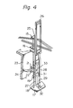
- the lower ends of the leg portions 42 and 43 of the skeleton heald 39 are connected to one end of a spring 44, the other end of which is secured to the machine frame 17 (see Fig. 4), and accordingly, the skeleton heald 39 is always urged downwardly by means of the spring 44.
- the standard warp Y 1 passes through a yarn guide 45 which is arranged outside of the heald frames 25 and 26 along a circle, and then, it passes through a space between the skeleton heald 39 and the inner or outer standard heald 37 or 38, and after it passes through a clearance formed between the adjacent vertical rods 47 which are disposed between the upper and lower shuttle guide rails 15 and 16, it extends to an inner guide gauge ring 46.
- the warps Y 1 and Y 2 and the weft Y 3 are crossed to form a fabric F.
- the leno warp Y 2 passes through the yarn guide 45, and then, it passes through the eye 41a of the skeleton heald 39, and thereafter, it passes through the clearance formed between the vertical rods, which clearance is the same as the clearance where the standard warp Y 1 passes through, and finally, it reaches the inner guide gauge ring 46.
- the inner and outer heald frames 25 and 26 are moved upwardly and downwardby as the shuttles 13 travel, as shown in Fig. 2. Since the leg portions 42 and 43 of the skeleton heald 39 are inserted into the eyes 37a and 37b of the inner standard heald 37 and the eyes 38a and 38b of the outer standard heald 38, respectively, the skeleton heald alternately moves to the left side and to the right side of the standard warp Y 1 as the shuttle 13 travels, and when the skeleton heald is moved upwards, it forms an open shed and a crossed shed.
- Fig. 5 illustrates a condition wherein an inner standard heald 37 is lifted and the outer standard heald 38 is lowered.
- the eye 37a of the inner standard heald 37 engages with the top portion 41 of the skeleton heald 39, and accordingly the skeleton heald 39 is lifted by means of the eye 37a of the standard heald 37 against the spring 44.
- the eye 37a of the inner standard heald 37 is moved upwardly beyond the shuttle 13, and the leno warp Y 2 is lifted beyond the shuttle 13 by means of the eye 41a formed in the top portion of the skeleton heald 39.
- the eye 38a of the outer standard heald 38 is lowered beyond the shuttle 13.
- the standard warp Y 1 passes through a gap between the leg portion 43 of the skeleton heald 39 and the standard heald 38 at a position above the eye 38a of the standard heald 38, and the standard warp Y l lies on a line connecting the yarn guide 45 and the inner guide gauge ring 46.
- the leno warp Y 2 is introduced to the upper side of the shuttle 13 by means of the eye 41a formed in the skeleton heald 39
- the standard warp Y 1 is introduced to the lower side of the shuttle 13 by means of the warp guide 14.
- the standard warp can be located below the center of the shuttle 13, and accordingly, it is preferable, from a practical point of view, because such a warp can smoothly be introduced to the lower side of the shuttle 13 by means of the warp guide 14 mounted on the shuttle 13.
- the standard heald 38 is lifted.
- the spring 44 serves to ensure the top portion 41 of the skeleton heald 39 to engage with the eye 37a of the standard heald 37, and the skeleton heald 39 is lowered following the movement of the eye 37a formed in the standard heald 37.
- the leno warp Y 2 is lowered by means of the eye 41a of the skeleton heald 39.
- the eye 38a of the standard heald 38 moves upwardly along the leg portion 43 of the skeleton heald 39 and engages with the standard warp Y 1 from below.
- the standard warp Y is raised along the leg portion 43 of the skeleton heald 39 by means of the inclined portion of the eye 38a formed in the standard heald 38.
- the eye 38a formed in the standard heald 38 engages with the top portion 41 of the skeleton heald 39, and the standard warp Y 1 is raised onto the top portion 41 of the skeleton heald 39. Thereafter, the skeleton heald 39 is lifted by means of the eye 38a formed in the standard heald 38, and contrary to this, the eye 37a formed in the standard heald 37 is lowered along the leg portion 42 of the skeleton heald 39. At this time, the standard warp Y is guided by the eye 38a formed in the standard heald 38 so as to pass over the top portion 41 of the skeleton heald 39, and the standard warp Y 1 is inserted into a gap between the skeleton heald 37 and the leg portion 42 of the skeleton heald 39.
- the leno warp Y 2 is guided by the eye 41a of the skeleton heald 39 and passes beneath the standard warp Y 1 .
- the positions of the leno warp Y 2 and the standard warp Y are exchanged with each other, and a crossing part is formed.
- the leno warp Y 2 is raised upwardly by means of the eye 41a formed in the skeleton heald 39, and contrary to this, the standard warp Y 1 follows the movement of the eye 37a of the standard heald 37 and lowers along the leg 42 of the skeleton heald 39.
- the eye 38a of the standard heald 38 is lifted above the shuttle 13, and the leno warp Y 2 is raised upwardly beyond the shuttle 13 by means of the eye 41a formed in the skeleton heald 39.
- the eye 37a of the standard heald 37 is lowered beyond the shuttle 13, and the standard warp Y 1 lies on a line connecting the yarn guide 45 and the inner guide gauge ring 46.
- the leno warp Y 2 is introduced to the upper side of the shuttle 13, and contrary to this, the standard warp Y 1 is introduced to the lower side of the shuttle 13.
- the standard heald 38 lowers, and the standard heald 37 lifts. Accordingly, the positions of the leno warp Y 2 and the standard warp Y 1 are exchanged with each other, and they again become in a condition illustrated in Fig. 5.
- Fig. 6 illustrates a relationship between the leno warp Y 2 , standard warp Y and the weft Y 3 withdrawn from the shuttle 13 which are illustrated in Fig. 5. Since the standard warp Y 1 is inserted into a gap between the leg portion 43 of the skeleton heald 39 and the standard heald 38, the leno warp Y 2 forming a shed is located above the standard warp Y 1 in Fig. 6 when it is seen in a direction perpendicular to the sheet on which Fig. 6 is illustrated.
- Fig. 8 illustrates the relationship between the leno warp Y 2 , the standard warp Y 1 ' and the weft Y 3 withdrawn from the shuttle 13 which are illustrated in Fig. 7.
- the leno warp Y 2 forming a shed in Fig. 8 is located below the standard warp Y 1 when it is seen in a direction perpendicular to the sheet on which Fig. 8 is illustrated, and the positions of the leno warp and standard warp Y 1 together forming a shed in Fig. 8 is reverse to those in Fig. 6.
- a plurality of doup healds arranged at the outer periphery of the circular shuttle guides are successively and alternately moved upwardly and downwardly.
- crossing parts of leno warps Y 2 with standard warps Y 1 can be formed between adjacent weft yarns. Consequently, a tubular fabric wherein the distance between the adjacent yarns is large can be produced, and the tubular fabric can be used to manufacture a bag which is suitable for the storage of onions, potatos and so on.
Abstract
A number of heald frames are circularly arranged in two rows, each inside row heald frame is interlocked to and forms a pair with an outside row frame. A pair of the heald frames support standard healds (37, 38) for a leno warp (Y2). a skeleton heald (39) is associated with the pair of standard healds (37, 38) and provided with an eye (41a) for guiding the leno warp (Y2). A ground warp (Y,) is maintained substantially in a still state, the leno warp (Y2) is raised and an opening is made at one side of the ground warp (Y,), passed under the ground warp (Y,) at the next opening, raised and opened, and a leno weave cylindrical fabric is thus woven.
Description
- The present invention relates to a method for manufacturing a leno weave tubular fabric in a circular loom and a circular loom for weaving a leno weave tubular fabric.
- Circular looms for weaving a tubular fabric have been known, and for example, the circular looms developed by the present inventor (see U.S. Patents No. 3,871,413 and No. 3,961,648), and the circular loom manufactured and sold by the British company, Fairbairn-Lawson Machinery, Ltd., are typical.
- As is well known, in circular looms of the above--mentioned types, an even number of shuttles are mounted on an annular shuttle guide member so that said shuttles can travel along this guide member, and an engaging means, such as press rollers, to be engaged with the corresponding shuttles, respectively, are moved along the shuttle guide member. Each shuttle is pressed by the corresponding engaging means and is propelled along the shuttle guide member. Wefts taken out from the respective shuttles are fabricated with warps sequentially opened on both the upper and lower sides of the respctive shuttles by healds, and a tubular fabric is thus formed. In this case, several healds are supported by a heald frame, and many heald frames are arrayed in two rows in a circular manner. A set composed of an inner heald frame and an outer heald frame in the circular array is moved up and down by a cylindrical cam mechanism which rotates in synchronism with the advance of the shuttle, and the individual sets are successively opened. A set of heald frames forming a shed in a shedding mechanism consists only of an inner heald frame and an outer heald frame. Therefore, with the conventional circular loom, only fabrics with a plain weave could be obtained; other woven fabrics with different weaves could not be obtained.
- Tubular fabrics woven in such a circular loom utilizing tapes of synthetic resins, such as polypropylene and polyethylene resins, or synthetic resin strands, such as multifilament yarns or cords of synthetic resins, as warps and wefts, have been widely used for bags for transportation and storage of various materials and shopping bags, because these bags are strong and light in weight.
- However, tubular fabrics woven in a conventional circular loom have a plain weave and are woven in such a manner that yarns are closedly located to each other, and accordingly, they have a disadvantage in that the air permeability is inferior. As a result, such a bag"is not suitable for the storage of vegetables, such as onions or potatos. If the weave density is reduced by decreasing the number of warps or wefts in order to enhance the air permeability, the yarns may easily become displaced, especially when synthetic tapes are used as warps and wefts, and then, there is the disadvantage of excessively large openings being formed in the tubular fabric.
- Leno weave is known as a weave by which good permeability can be obtained and by which the displacement of yarns can be prevented. In leno weave, crossing parts are formed between the wefts, and therefore, the distance between the yarns can be enlarged, while the displacement of yarns do not occur.
- Incidentally, in an ordinary loom, four healds are usually utilized in order to weave a woven fabric with leno weave. More specifically, there are two healds for a standard warp and a leno warp, and two doup healds consisting of a standard heald and a skeleton heald.
- However, since a shedding mechanism of a conventional circular loom moves heald frames up and down by means of a cylindrical cam mechanism, it is difficult to employ three or more heald frames to constitute a set of frames. If it is attempted to design a shedding mechanism to be capable of moving three or more heald frames up and down, the structure of such a shedding mechanism will become very complicated, and the weaving speed will be decreased, and accordingly, such a loom will be unpractical.
- An object of the present invention is to provide a tubular fabric which has good air permeability and which is free from substantial displacement of constituent yarns.
- Another object of the present invention is to provide a method for manufacturing a leno weave tubular fabric, using a shedding mechanism consisting of a plurality of heald frames that are arrayed in two rows in a circular manner, the same as in a conventional manner, and of a circular cam mechanism for moving the heald frames up and down; and the present invention further relates to a circular loom for effecting the method.
- According to one aspect of the present invention, the objects are achieved by a method for manufacturing a leno weave tubular fabric in a circular loom characterized in that a standard warp is kept in a substantially stationary condition without being subjected to a positive shedding motion, a leno warp is lifted on one side of the standard warp to form a shed, and at the next shedding, the leno warp is lifted on the opposite side of the standard warp to form a shed after the leno warp passes beneath the standard warp, and the shedding motion of the leno warp is repeated.
- According to another aspect of the present invention, the objects are accomplished by a circular loom for weaving a leno weave tubular fabric comprising a plurality of heald frames arranged in two rows along two concentric circles, each inner heald frame and corresponding outer heald frame forming a pair, the pair being constructed in such a manner that when one of the heald frames forming the pair is lifted or lowered, the other heald frame is lowered or lifted, characterized in that the heald frames forming the pair support standard healds for a leno warp, and a skeleton heald is incorporated with the pair of standard healds, the skeleton heald being provided with an eye for guiding the leno warp, and a yarn passage in the weaving zone is restricted by: a yarn guide arranged along a circle outside of the heald frames; a clearance formed between vertical rods arranged along a circle inside of the heald frames; and an inner guide gauge ring guiding the woven fabric.
-
- Fig. 1 is a perspective view of an embodiment of a circular loom according to the present invention;
- Fig. 2 is a developed view showing the relationship between a plurality of shuttles, a plurality of heald frames and a mechanism for the shedding motion of the present invention;
- Fig. 3 is a diagrammatical perspective view illustrating a doup heald, yarn guides and an inner guide gauge ring of the present invention;
- Fig. 4 is a perspective view illustrating a doup heald frame and a mechanism for the shedding motion of the present invention, wherein the doup heald is removed in order to facilitate easy understanding of the mechanism;
- Fig. 5 is a schematic view illustrating a condition wherein an inner standard heald of the doup heald is lifted and an outer standard heald is lowered;
- Fig. 6 is a view illustrating the relationship between a standard warp, leno warp and weft under the condition illustrated in Fig. 5;
- Fig. 7 is a schematic view illustrating a condition wherein an inner standard heald is lowered and an outer standard heald is lifted;
- Fig. 8 is a view illustrating the relationship between a standard warp, leno warp and weft under the condition illustrated in Fig. 7; and
- Fig. 9 is a view illustrating the weave structure of a tubular fabric manufactured by a circular loom of the present invention.
- Fig. 1 illustrates an embodiment of a circular loom according to the present invention. In the
circular loom 1 illustrated in Fig. 1, aweaving zone 4, including a shed forming means and a filling means, is mounted within aframe 9, and the shed forming means and the filling means are driven by anelectric motor 5, disposed at the lower portion of theframe 9, through a first power transmission mechanism (not shown). At a position above the weaving zone, ameans 8 for taking up the woven tubular fabric is disposed and is driven through a second power transmission mechanism (not shown). The second power transmission mechanism is driven by the first power transmission mechanism through a driving transmission lever 11 so that the taking up means is driven in synchronism with the weaving zone.Warps 3, in a number necessary for weaving a desirabletubular fabric 2, are fed to a pair ofcreels 6 disposed on both the sides of theweaving zone 4 symmetrically with each other with respect to the weaving zone 4 (only one creel, disposed on the right side, is illustrated in Fig. 1), from a plurality ofpackages 6a rotatably mounted for feeding warps, and thewarps 3 are fed to theweaving zone 4 through warp feed-out means 7. Thetubular fabric 2 formed by the weaving operation in theweaving zone 4 of thecircular loom 1 is upwardly taken out by the woven fabric taking upmeans 8 and guided to a winding means (not shown) in a direction indicated by an arrow. - In the
weaving zone 4 of the circular loom, a plurality of heald frames are arrayed in two rows along two concentric circles, each inner heald frame 25 (Fig. 2) of which is paired with a correspondingouter heald frame 26. The pair is constructed in such a manner that when one of heald frames forming the pair is lifted or lowered, the other heald frame is correspondingly lowered or lifted. As shown in Fig. 2, in this circular loom, a plurality of pairs of heald frames perform a wave-like shedding motion, and a plurality ofshuttles 13 provided withwarp yarn guides 14 pass through the sheds. - Referring to Figs. 2 and 4, a shedding motion mechanism for vertically moving the heald frames will now be briefly explained. In this circular loom, a plurality of
guide rods 18 are disposed between a lowershuttle guide rail 16 and amachine frame 17, and eachguide rod 18 has asliding piece 19 slidably mounted thereon. Thesliding piece 19 has tworollers cam projection 24 formed on the side surface of acam disc 23. Thecam projection 24 is formed in a wave shape as illustrated at the lower portion of Fig. 2. As thecam disc 23 rotates while the loom is operated, thesliding piece 19 is vertically moved along theguide rod 18. - The
inner heald frame 25 and theouter heald frame 26 have supportingsheets sheets endless belt 29 by means of an appropriate securing means. Theendless belt 29 is wrapped around twoguide pulleys sheet 27 attached to theinner heald frame 25 is secured to thesliding piece 19 by means of apin 33. Accordingly, as thesliding piece 19 is vertically moved due to the rotation of thecam disc 23, theinner heald frame 25 and theouter heald frame 26 are also vertically moved. Fig. 2 illustrates the locational relationship between theshuttles 13, thesliding pieces 19, and inner andouter heald frames - As illustrated in Fig. 3, the heald utilized in the present invention is not an ordinary heald, but a doup heald. The inner and
outer heald frames lower bars 35 for supporting healds mounted at the upper and lower portions thereof, which bars supportstandard healds standard heald eye eyes upper eye standard heald standard heald outer heald frames top portion 41 of theskeleton heald 39 has aneye 41a for guiding the leno warp formed therein, and twoleg portions eyes standard healds leg portions skeleton heald 39 are connected to one end of aspring 44, the other end of which is secured to the machine frame 17 (see Fig. 4), and accordingly, theskeleton heald 39 is always urged downwardly by means of thespring 44. - In the weaving zone of the circular loom, the standard warp Y1 passes through a
yarn guide 45 which is arranged outside of the heald frames 25 and 26 along a circle, and then, it passes through a space between theskeleton heald 39 and the inner orouter standard heald vertical rods 47 which are disposed between the upper and lowershuttle guide rails guide gauge ring 46. At the innerguide gauge ring 46, the warps Y1 and Y2 and the weft Y3 are crossed to form a fabric F. - Contrary to this, the leno warp Y2 passes through the
yarn guide 45, and then, it passes through theeye 41a of theskeleton heald 39, and thereafter, it passes through the clearance formed between the vertical rods, which clearance is the same as the clearance where the standard warp Y1 passes through, and finally, it reaches the innerguide gauge ring 46. - The inner and outer heald frames 25 and 26 are moved upwardly and downwardby as the
shuttles 13 travel, as shown in Fig. 2. Since theleg portions skeleton heald 39 are inserted into theeyes inner standard heald 37 and theeyes outer standard heald 38, respectively, the skeleton heald alternately moves to the left side and to the right side of the standard warp Y1 as theshuttle 13 travels, and when the skeleton heald is moved upwards, it forms an open shed and a crossed shed. - Fig. 5 illustrates a condition wherein an
inner standard heald 37 is lifted and theouter standard heald 38 is lowered. In this case, theeye 37a of theinner standard heald 37 engages with thetop portion 41 of theskeleton heald 39, and accordingly theskeleton heald 39 is lifted by means of theeye 37a of thestandard heald 37 against thespring 44. Theeye 37a of theinner standard heald 37 is moved upwardly beyond theshuttle 13, and the leno warp Y2 is lifted beyond theshuttle 13 by means of theeye 41a formed in the top portion of theskeleton heald 39. Theeye 38a of theouter standard heald 38 is lowered beyond theshuttle 13. The standard warp Y1 passes through a gap between theleg portion 43 of theskeleton heald 39 and thestandard heald 38 at a position above theeye 38a of thestandard heald 38, and the standard warp Yl lies on a line connecting theyarn guide 45 and the innerguide gauge ring 46. When theshuttle 13 travels, the leno warp Y2 is introduced to the upper side of theshuttle 13 by means of theeye 41a formed in theskeleton heald 39, and the standard warp Y1 is introduced to the lower side of theshuttle 13 by means of thewarp guide 14. In this case, if the position of theyarn guide 45 is set below the imaginary horizontal plane H including the center of theshuttle 13 therein as illustrated in the drawings, the standard warp can be located below the center of theshuttle 13, and accordingly, it is preferable, from a practical point of view, because such a warp can smoothly be introduced to the lower side of theshuttle 13 by means of thewarp guide 14 mounted on theshuttle 13. - After the
shuttle 13 passes through a gap between the leno warp Y2 and the standard yarp Y1 , thestandard heald 38 is lifted. Thespring 44 serves to ensure thetop portion 41 of theskeleton heald 39 to engage with theeye 37a of thestandard heald 37, and theskeleton heald 39 is lowered following the movement of theeye 37a formed in thestandard heald 37. The leno warp Y2 is lowered by means of theeye 41a of theskeleton heald 39. Theeye 38a of thestandard heald 38 moves upwardly along theleg portion 43 of theskeleton heald 39 and engages with the standard warp Y1 from below. The standard warp Y is raised along theleg portion 43 of theskeleton heald 39 by means of the inclined portion of theeye 38a formed in thestandard heald 38. - The
eye 38a formed in thestandard heald 38 engages with thetop portion 41 of theskeleton heald 39, and the standard warp Y1 is raised onto thetop portion 41 of theskeleton heald 39. Thereafter, theskeleton heald 39 is lifted by means of theeye 38a formed in thestandard heald 38, and contrary to this, theeye 37a formed in thestandard heald 37 is lowered along theleg portion 42 of theskeleton heald 39. At this time, the standard warp Y is guided by theeye 38a formed in thestandard heald 38 so as to pass over thetop portion 41 of theskeleton heald 39, and the standard warp Y1 is inserted into a gap between theskeleton heald 37 and theleg portion 42 of theskeleton heald 39. The leno warp Y2 is guided by theeye 41a of theskeleton heald 39 and passes beneath the standard warp Y1. As a result, the positions of the leno warp Y2 and the standard warp Y are exchanged with each other, and a crossing part is formed. The leno warp Y2 is raised upwardly by means of theeye 41a formed in theskeleton heald 39, and contrary to this, the standard warp Y1 follows the movement of theeye 37a of thestandard heald 37 and lowers along theleg 42 of theskeleton heald 39. - As illustrated in Fig. 7, the
eye 38a of thestandard heald 38 is lifted above theshuttle 13, and the leno warp Y2 is raised upwardly beyond theshuttle 13 by means of theeye 41a formed in theskeleton heald 39. Theeye 37a of thestandard heald 37 is lowered beyond theshuttle 13, and the standard warp Y1 lies on a line connecting theyarn guide 45 and the innerguide gauge ring 46. Thereafter, when thenext shuttle 13 travels, the leno warp Y2 is introduced to the upper side of theshuttle 13, and contrary to this, the standard warp Y1 is introduced to the lower side of theshuttle 13. After theshuttle 13 passes through, thestandard heald 38 lowers, and thestandard heald 37 lifts. Accordingly, the positions of the leno warp Y2 and the standard warp Y1 are exchanged with each other, and they again become in a condition illustrated in Fig. 5. - Fig. 6 illustrates a relationship between the leno warp Y2 , standard warp Y and the weft Y3 withdrawn from the
shuttle 13 which are illustrated in Fig. 5. Since the standard warp Y1 is inserted into a gap between theleg portion 43 of theskeleton heald 39 and thestandard heald 38, the leno warp Y2 forming a shed is located above the standard warp Y1 in Fig. 6 when it is seen in a direction perpendicular to the sheet on which Fig. 6 is illustrated. Fig. 8 illustrates the relationship between the leno warp Y2 , the standard warp Y1 ' and the weft Y3 withdrawn from theshuttle 13 which are illustrated in Fig. 7. Since the standard warp Y1 is inserted into a gap between theleg portion 42 of theskeleton heald 39 and thestandard heald 37, the leno warp Y2 forming a shed in Fig. 8 is located below the standard warp Y1 when it is seen in a direction perpendicular to the sheet on which Fig. 8 is illustrated, and the positions of the leno warp and standard warp Y1 together forming a shed in Fig. 8 is reverse to those in Fig. 6. - The operations explained in conjunction with Figs. 5 and 7 are successively and alternately repeated by means of a plurality of the doup healds arranged on the shuttle guides 15 and 16. Accordingly, crossing parts of the leno warps Y2 engaging with the doup healds with the standard warps Y1 are formed between the adjacent weft yarns Y3 withdrawn from the
shuttles 13. As a result, a leno weavetubular fabric 2, which has a weave structure as illustrated in Fig. 9, is woven. The thus produced leno weavetubular fabric 2 is guided to the innerguide gauge ring 46, from which thefabric 2 is taken up upwardly. - As is apparent from the above-explained embodiment, in the present invention, a plurality of doup healds arranged at the outer periphery of the circular shuttle guides are successively and alternately moved upwardly and downwardly. According to this construction, crossing parts of leno warps Y2 with standard warps Y1 can be formed between adjacent weft yarns. Consequently, a tubular fabric wherein the distance between the adjacent yarns is large can be produced, and the tubular fabric can be used to manufacture a bag which is suitable for the storage of onions, potatos and so on.
Claims (5)
1. A method for manufacturing a leno weave tubular fabric in a circular loom characterized in that a standard warp is kept in a substantially stationary condition without being subjected to a positive shedding motion, a leno warp is caused to be lifted on one side of said standard warp to form a shed, and at a next shedding, said leno warp is caused to be lifted on the opposite side of said standard warp to form a shed after said leno warp passes beneath said standard warp, and the shedding motion of said leno warp is repeated.
2. A circular loom for weaving a leno weave tubular fabric comprising a plurality of heald frames arranged in two rows along two concentric circles, each inner heald frame and corresponding outer heald frame forming a pair, said pair being constructed in such a manner that when one of said heald frames forming said pair is lifted or lowered, the other heald frame is lowered or lifted, characterized in that: said heald frames forming said pair support standard healds for a leno warp; a skeleton heald is incorporated with said pair of standard healds, said skeleton heald being provided with an eye for guiding said leno warp; and a yarn passage in a weaving zone is restricted by a yarn guide arranged along a circle outside of said heald frames, a clearance formed between adjacent vertical rods arranged along a circle inside of said heald frames, and an inner guide gauge ring for guiding a woven fabric.
3. A circular loom according to claim 2, wherein said yarn guide for guiding said standard warp is located below an imaginary horizontal plane passing through the centers of shuttles.
4. A circular loom according to claim 2 or 3, wherein said skeleton heald has a top portion, provided with said eye for guiding said leno warp, and two leg portions extending downwardly from said top portion, one of said two leg portions passing through an eye formed in said inner standard heald and the other of said two leg portions passing through an eye formed in said outer standard heald, said skeleton heald being urged downwardly by means of a spring.
5. A circular loom according to claim 4, wherein said eyes of said inner and outer standard healds have portions downwardly inclined toward the opposite standard healds, respectively.
Applications Claiming Priority (2)
| Application Number | Priority Date | Filing Date | Title |
|---|---|---|---|
| JP106507/80 | 1980-08-01 | ||
| JP10650780A JPS5735028A (en) | 1980-08-01 | 1980-08-01 | Method and circular loom for weaving entangled cylindrical cloth |
Publications (2)
| Publication Number | Publication Date |
|---|---|
| EP0057237A1 true EP0057237A1 (en) | 1982-08-11 |
| EP0057237A4 EP0057237A4 (en) | 1982-11-25 |
Family
ID=14435335
Family Applications (1)
| Application Number | Title | Priority Date | Filing Date |
|---|---|---|---|
| EP19810902245 Withdrawn EP0057237A4 (en) | 1980-08-01 | 1981-07-30 | Method of producing leno weave cylindrical fabric and circular loom for executing the same. |
Country Status (7)
| Country | Link |
|---|---|
| EP (1) | EP0057237A4 (en) |
| JP (1) | JPS5735028A (en) |
| KR (1) | KR840001904B1 (en) |
| IT (1) | IT1137763B (en) |
| PH (1) | PH19067A (en) |
| PT (1) | PT73451B (en) |
| WO (1) | WO1982000480A1 (en) |
Cited By (6)
| Publication number | Priority date | Publication date | Assignee | Title |
|---|---|---|---|---|
| AT387993B (en) * | 1986-09-01 | 1989-04-10 | Chemiefaser Lenzing Ag | SPECIALIST EDUCATION DEVICE FOR TURNBINDING |
| FR2685358A1 (en) * | 1991-12-19 | 1993-06-25 | Commissariat Energie Atomique | Three-dimensional fabric, method of manufacturing this fabric and devices for the implementation of this method |
| WO1999023288A1 (en) * | 1997-11-03 | 1999-05-14 | Klöcker-Entwicklungs-Gmbh | Device for regulating the thread tension of doup end threads and standing end threads guided through a gauze selvedge device |
| EP1967623A2 (en) | 2007-03-07 | 2008-09-10 | STARLINGER & CO. GESELLSCHAFT MBH | Circular loom |
| CN106081716A (en) * | 2016-07-29 | 2016-11-09 | 天津市旭辉恒远塑料包装股份有限公司 | Knitting machine winder |
| CN112410995A (en) * | 2020-11-10 | 2021-02-26 | 邵阳市昌兴实业有限公司 | Yarn anti-winding device |
Families Citing this family (4)
| Publication number | Priority date | Publication date | Assignee | Title |
|---|---|---|---|---|
| KR100893950B1 (en) * | 2007-10-01 | 2009-04-22 | (주)유성특수산업 | Weaving device for leno fabrics |
| EP2063007B1 (en) * | 2007-11-21 | 2010-09-29 | Groz-Beckert KG | Device for making leno fabrics |
| KR101067238B1 (en) * | 2008-12-18 | 2011-09-26 | 박상구 | method for manufacturing wire heald and wire heald thereof |
| EP4065758A4 (en) * | 2019-11-26 | 2023-12-20 | Lohia Corp Limited | A circular loom for manufacturing doup fabric and a method for manufacturing it |
Family Cites Families (3)
| Publication number | Priority date | Publication date | Assignee | Title |
|---|---|---|---|---|
| JPS4416384Y1 (en) * | 1966-11-29 | 1969-07-15 | ||
| JPS5547139B2 (en) * | 1972-12-26 | 1980-11-28 | ||
| JPS5063271A (en) * | 1973-10-11 | 1975-05-29 |
-
1980
- 1980-08-01 JP JP10650780A patent/JPS5735028A/en active Pending
-
1981
- 1981-07-30 PH PH25987A patent/PH19067A/en unknown
- 1981-07-30 EP EP19810902245 patent/EP0057237A4/en not_active Withdrawn
- 1981-07-30 PT PT73451A patent/PT73451B/en unknown
- 1981-07-30 WO PCT/JP1981/000171 patent/WO1982000480A1/en not_active Application Discontinuation
- 1981-07-31 IT IT23282/81A patent/IT1137763B/en active
- 1981-08-01 KR KR1019810002802A patent/KR840001904B1/en active
Non-Patent Citations (2)
| Title |
|---|
| None * |
| See also references of WO8200480A1 * |
Cited By (8)
| Publication number | Priority date | Publication date | Assignee | Title |
|---|---|---|---|---|
| AT387993B (en) * | 1986-09-01 | 1989-04-10 | Chemiefaser Lenzing Ag | SPECIALIST EDUCATION DEVICE FOR TURNBINDING |
| FR2685358A1 (en) * | 1991-12-19 | 1993-06-25 | Commissariat Energie Atomique | Three-dimensional fabric, method of manufacturing this fabric and devices for the implementation of this method |
| WO1999023288A1 (en) * | 1997-11-03 | 1999-05-14 | Klöcker-Entwicklungs-Gmbh | Device for regulating the thread tension of doup end threads and standing end threads guided through a gauze selvedge device |
| US6244304B1 (en) | 1997-11-03 | 2001-06-12 | Klocker-Entwicklungs Gmbh | Doup end tension regulating device for a selvedge former |
| EP1967623A2 (en) | 2007-03-07 | 2008-09-10 | STARLINGER & CO. GESELLSCHAFT MBH | Circular loom |
| CN106081716A (en) * | 2016-07-29 | 2016-11-09 | 天津市旭辉恒远塑料包装股份有限公司 | Knitting machine winder |
| CN112410995A (en) * | 2020-11-10 | 2021-02-26 | 邵阳市昌兴实业有限公司 | Yarn anti-winding device |
| CN112410995B (en) * | 2020-11-10 | 2022-03-22 | 邵阳市昌兴实业有限公司 | Yarn anti-winding device |
Also Published As
| Publication number | Publication date |
|---|---|
| JPS5735028A (en) | 1982-02-25 |
| PH19067A (en) | 1985-12-17 |
| KR830006499A (en) | 1983-09-24 |
| IT1137763B (en) | 1986-09-10 |
| WO1982000480A1 (en) | 1982-02-18 |
| IT8123282A0 (en) | 1981-07-31 |
| PT73451B (en) | 1982-10-21 |
| EP0057237A4 (en) | 1982-11-25 |
| PT73451A (en) | 1981-08-01 |
| KR840001904B1 (en) | 1984-10-24 |
Similar Documents
| Publication | Publication Date | Title |
|---|---|---|
| EP0481772B1 (en) | Tubular multilayer woven fabric and method for manufacturing the same | |
| EP0057237A1 (en) | Method of producing leno weave cylindrical fabric and circular loom for executing the same | |
| US5592977A (en) | Multi-layered woven belt with rope shaped portion | |
| US3961648A (en) | Positive shedding motion device for a circular loom | |
| GB2113725A (en) | Circular looms | |
| US20050011576A1 (en) | Tetraxial fabric and machine for its manufacture | |
| US5375627A (en) | Method and weaving machine for producing multi-axial fabric | |
| GB1483224A (en) | Warp beams for triaxial weaving and method and apparatus for producing such warp beams | |
| Sondhelm | Technical fabric structures–1. Woven fabrics | |
| US3463199A (en) | Selvage-forming apparatus for double fabric looms | |
| JPS6320933B2 (en) | ||
| EP0957191B1 (en) | Method and apparatus for manufacturing textile articles | |
| US4846229A (en) | Circular loom | |
| US3016068A (en) | Loom for weaving non-cylindrical fabrics | |
| US1787491A (en) | Loom | |
| US4579149A (en) | Circular loom | |
| US4368760A (en) | Pile fabric and method for manufacture thereof | |
| US5099891A (en) | Shed-forming mechanism for a circular loom | |
| US4463782A (en) | Shedding apparatus for circular weaving of multi-harness fabrics and method of using the apparatus | |
| US5472020A (en) | Multi-axial fabric with triaxial and quartaxial portions | |
| KR910002113B1 (en) | Circular loom | |
| US4796674A (en) | Shed-forming apparatus for doup weave | |
| Hamdani | Introduction to weaving | |
| KR800000878Y1 (en) | Circular weaving loom | |
| JPH0336544Y2 (en) |
Legal Events
| Date | Code | Title | Description |
|---|---|---|---|
| PUAI | Public reference made under article 153(3) epc to a published international application that has entered the european phase |
Free format text: ORIGINAL CODE: 0009012 |
|
| 17P | Request for examination filed |
Effective date: 19820402 |
|
| AK | Designated contracting states |
Designated state(s): AT FR GB |
|
| STAA | Information on the status of an ep patent application or granted ep patent |
Free format text: STATUS: THE APPLICATION IS DEEMED TO BE WITHDRAWN |
|
| 18D | Application deemed to be withdrawn |
Effective date: 19840411 |
|
| RIN1 | Information on inventor provided before grant (corrected) |
Inventor name: TORII, SOICHI |