EP0057101A2 - Rolling mill stand - Google Patents
Rolling mill stand Download PDFInfo
- Publication number
- EP0057101A2 EP0057101A2 EP82300374A EP82300374A EP0057101A2 EP 0057101 A2 EP0057101 A2 EP 0057101A2 EP 82300374 A EP82300374 A EP 82300374A EP 82300374 A EP82300374 A EP 82300374A EP 0057101 A2 EP0057101 A2 EP 0057101A2
- Authority
- EP
- European Patent Office
- Prior art keywords
- stand
- mill
- bed plate
- rolling mill
- stands
- Prior art date
- Legal status (The legal status is an assumption and is not a legal conclusion. Google has not performed a legal analysis and makes no representation as to the accuracy of the status listed.)
- Granted
Links
Images


Classifications
-
- B—PERFORMING OPERATIONS; TRANSPORTING
- B21—MECHANICAL METAL-WORKING WITHOUT ESSENTIALLY REMOVING MATERIAL; PUNCHING METAL
- B21B—ROLLING OF METAL
- B21B13/00—Metal-rolling stands, i.e. an assembly composed of a stand frame, rolls, and accessories
- B21B13/001—Convertible or tiltable stands, e.g. from duo to universal stands, from horizontal to vertical stands
-
- B—PERFORMING OPERATIONS; TRANSPORTING
- B21—MECHANICAL METAL-WORKING WITHOUT ESSENTIALLY REMOVING MATERIAL; PUNCHING METAL
- B21B—ROLLING OF METAL
- B21B31/00—Rolling stand structures; Mounting, adjusting, or interchanging rolls, roll mountings, or stand frames
- B21B31/08—Interchanging rolls, roll mountings, or stand frames, e.g. using C-hooks; Replacing roll chocks on roll shafts
- B21B31/10—Interchanging rolls, roll mountings, or stand frames, e.g. using C-hooks; Replacing roll chocks on roll shafts by horizontally displacing, i.e. horizontal roll changing
Definitions
- This invention relates to a rolling mill stand and is particularly concerned with a rolling mill, as sometimes used for-the rolling of rod, bar and sections, having a number of stands spaced along the pass line and constructed to enable at least some of the stands to be removed bodily from the mill line for servicing and to be replaced by substitute stands.
- An object of the present invention is to facilitate the introduction and removal of a stand from a multi-stand mill, with the aim of keeping the mill down-time to a low figure.
- the present invention resides in a replaceable rolling mill stand having a bed plate which is attached to the stand and which is adapted to be removed from the mill with the stand for servicing of the latter and to be introduced into the mill with the stand, and means carried by the bed plate for securing a guide or guides in preselected position relative to the bed plate, whereby the guide or guides may be fitted prior to introduction of the stand to the mill to take up automatically a pass-line position or positions after the stand has been. brought to the mill.
- the bed plate is mounted on wheels which facilitate the movement of the bed plate and stand into and out of the mill.
- the guide or guides By having on the bed plate mounting means for the guide or guides, the latter may be fitted prior to introduction of the stand to the mill so as to take up automatically a pass-line position or positions after the bed plate has been brought to the mill.
- the time-consuming operation of locating the guide or guides accurately in relation to the intended pass-line is then performed away from the mill line, and without consuming potential production time.
- the stand is secured on the bed plate for adjustment transversely of the pass-line; consequently, in the case of a rod or bar mill, any desired roll groove can be brought into alignment with the pass-line.
- Rod and bar mills can have both horizontal and vertical stands. It is an auxiliary feature of this invention to provide means at the mill for rotating the stand complete with guides as described above on introduction into a vertical stand disposition.
- a stand of a bar and section mill is indicated generally at 12, mounted on its bed plate carriage 13.
- the construction of the stand itself is self evident from the drawing and will not be further described, except to point out that the stand housing has a pair of feet 14 extending outwardly at each side.
- the stand For roll change and servicing generally, the stand, with its bed plate carriage 13, is bodily removed from the mill line, and is replaced by a substitute stand and bed plate carriage, to keep the down-time of the mill at a minimum.
- the stand which has been removed from the mill can be moved to the roll shop and be serviced whilst the mill is in production.
- the carriage 13 is permanently associated with the stand, which remains on the carriage, except when it is necessary to separate the two for servicing.
- the carriage 13 is mounted on two pairs of wheels, of which one pair 16 is unflanged while the other pair 17 is double flanged. At one end the carriage has a C-hook 18 enabling the carriage and stand to be drawn into the mill line, as will be explained subsequently.
- Each side of the carriage 15 is constituted by an upright plate 19, Figure 4, from which a plate 20 inwardly projects over the whole length of the carriage, the two plates 20 constituting the bed plate of the stand.
- the plates 20 are also shown in Figure 1 and it will be observed that the feet 14 rest on the bedplates through wearing plates 21. The feet are retained on the bedplates by keepers 22 secured to the top of the plates 19 and projecting over the feet.
- the feet on both sides of the housing contain a captive nut, the position of which is indicated in Figure 2 at 23.
- a screw meshes with the captive nuts on that side of the stand and is connected to a drive system.
- the stand can be adjusted on the bed plate 13 in a direction parallel to the axis of the stand rolls, in order to bring any selected roll groove to the pass-line.
- On the centre line of the carriage there are two spaced pillars 25 on which are mounted stand guides 26 ( Figures 3 and 4), which, when the carriage is in its position in the mill line are aligned at each side of the rolls with the pass-line.
- the replacement stands intended to replace those in the rolling line are prepared in the roll shop while the mill is running and the guides 26 are properly positioned on the pillars 25.
- the replacement stands Prior to stand changing, the replacement stands are moved out of the roll shop on rails 30 ( Figure 8) on which the wheels 16, 17 of the stand carriages run.
- the stands with their carriages are lifted by crane off the rails 30 on to a series of wheel-mounted bogies 31.
- Each such bogie 31 is sufficiently long to receive simultaneously two stands and the bogies are connected together by links 32, the whole train being in turn connected to a continuous drive chain by which the train can be moved on rails 33.
- Each bogie 31 receives only one replacement stand, leaving room for the reception of the stand it is to replace.
- the train of bogies 31 carrying the replacement stands 12 are moved on rails 33 parallel to the pass-line until there is a bogie opposite each stand location at which stand changing is to take place.
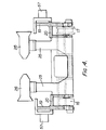
- the existing stands are released and each is pushed out of the mill line on its carriage 13 by means of a hydraulic piston-and- cylinder assembly 35 ( Figure 5) carrying at its end a hitch 36 which engages with the C-hook 18 ( Figure 3).
- the stand is moved on a rail for the 'flanged wheels 17 on to the vacant position of the adjacent bogie 31, which carries a similar and aligned rail 37 ( Figure 8).
- the train of bogies 31 is indexed parallel to the mill line, to bring the replacement stands into line with the stand positions in the mill line. They are then moved on their carriages 13 in a direction normal to the movement of the bogies into the mill line, using the assembly 35 and hitch 36 as before until fixed stops (not shown) are reached. Those stops ensure that each replacement stand is brought to a fixed and predetermined position relative to the mill pass-line with the pre-prepared guides 26 automatically aligned with the pass-line. In the final movement of each stand into its proper location in the mill line, wedges on the underside of each carriage 13 engage with wedges on the foundations to lift the carriage off its wheels and to lock the stand in position. The chain of bogies 31 carrying the withdrawn stands are returned and the stands lifted off the bogies on to the rails 30 ( Figure 8) for subsequent movement to the roll shop and for the necessary servicing.
- a platform 40 ( Figure 6), which is mounted on horizontal pins 41 and which carries rails on which the carriage wheels 16 can run.
- the platform 40 is moved between its horizontal disposition shown in Figure 6 in full line, into a-vertical disposition shown in chain line, by operation of a piston and cylinder device 42A ( Figure 5) connected with the platform by cylinder rod 42.
- the replacement stand and its carriage is drawn from the bogey 31 on to the platform 40 by means of the hitch 36; the platform 40 is then turned into its vertical disposition, to bring the stand 12 in position as a vertical stand, as shown in chain line in Figure 6.
- Figure 5 shows the general arrangement at a vertical stand location, including the hitch 36 and the platform 40. At that location, there is a mechanism for lifting the vertical stand to bring it into the pass-line. That mechanism is best shown in Figure 7, which shows two screw jacks disposed on opposite sides of the stand 12 and comprising screws 50 supported and driven by nuts which are located in housings 51 and which are driven through worm and worm wheel gears by a motor 52. An elevating member 53 is carried by each screw 50 and has a recess 54 leading to a cradle 55 ( Figure 5). When the replacement stand is drawn on to the (horizontal) platform 40, the cradles 55 are positioned below the pivot pins 41 of the platform.
- a pair of stub axles 57 extending outwardly from the carriage 13 are received in the recesses 54 above the cradles 55.
- the motor 52 is operated to lift the members 53 in their slideways 58, first to bring the stub axles 57 into the cradles 55, and then to take the weight of the stand.
- Platform 40 is then turned into its vertical position after which the stand is moved to its working position by operating the screw jacks 51. Selection of the rolling groove is effected by adjustment of the screw jacks.
- Figure 5 also shows the overhead pinion box 60 which is driven by the mill motor through shafts 61 and 62 and the output shafts 63 of which are coupled through conventional drive spindles to the rolls of the stand 12.
Landscapes
- Engineering & Computer Science (AREA)
- Mechanical Engineering (AREA)
- Metal Rolling (AREA)
- Bending Of Plates, Rods, And Pipes (AREA)
Abstract
Description
- This invention relates to a rolling mill stand and is particularly concerned with a rolling mill, as sometimes used for-the rolling of rod, bar and sections, having a number of stands spaced along the pass line and constructed to enable at least some of the stands to be removed bodily from the mill line for servicing and to be replaced by substitute stands.
- In such a mill, it is important that product changing should be effected with minimum delay to minimize the down-time of the mill and to maximize its effective use; it is indeed for those reasons that stand changing, rather than roll changing, is chosen for that purpose. At present, time is lost during product changing by the need to remove the guides at each stand before roll removal from the mill and, more importantly, by the need accurately to reposition the guides after the replacement rolls have been brought to the mill line.
- An object of the present invention is to facilitate the introduction and removal of a stand from a multi-stand mill, with the aim of keeping the mill down-time to a low figure.
- The present invention resides in a replaceable rolling mill stand having a bed plate which is attached to the stand and which is adapted to be removed from the mill with the stand for servicing of the latter and to be introduced into the mill with the stand, and means carried by the bed plate for securing a guide or guides in preselected position relative to the bed plate, whereby the guide or guides may be fitted prior to introduction of the stand to the mill to take up automatically a pass-line position or positions after the stand has been. brought to the mill. Advantageously, the bed plate is mounted on wheels which facilitate the movement of the bed plate and stand into and out of the mill.
- By having on the bed plate mounting means for the guide or guides, the latter may be fitted prior to introduction of the stand to the mill so as to take up automatically a pass-line position or positions after the bed plate has been brought to the mill. The time-consuming operation of locating the guide or guides accurately in relation to the intended pass-line is then performed away from the mill line, and without consuming potential production time.
- Preferably, the stand is secured on the bed plate for adjustment transversely of the pass-line; consequently, in the case of a rod or bar mill, any desired roll groove can be brought into alignment with the pass-line.
- Rod and bar mills can have both horizontal and vertical stands. It is an auxiliary feature of this invention to provide means at the mill for rotating the stand complete with guides as described above on introduction into a vertical stand disposition.
- The invention will be more readily understood by way of example from the following description of a rolling mill in accordance therewith, reference being made to the accompanying drawings, in which
- Figures 1 and 2 are respectively an end view and a side view of a stand of a bar and section mill,
- Figure 3 is a plan view of the bed plate carriage of the stand of Figures 1 and 2, while Figure 4 is a section on the line C-C of Figure 3,
- Figure 5 shows the arrangement for turning a stand into the vertical disposition,
- Figure 6 shows in greater detail the mechanism for rotating the stand,
- Figure 7 shows the mechanism for lifting a vertical stand, and
- Figure 8 shows the movement of a train of new stands to the rolling mill line.
- In Figures 1 and 2, a stand of a bar and section mill is indicated generally at 12, mounted on its
bed plate carriage 13. The construction of the stand itself is self evident from the drawing and will not be further described, except to point out that the stand housing has a pair offeet 14 extending outwardly at each side. - For roll change and servicing generally, the stand, with its
bed plate carriage 13, is bodily removed from the mill line, and is replaced by a substitute stand and bed plate carriage, to keep the down-time of the mill at a minimum. The stand which has been removed from the mill can be moved to the roll shop and be serviced whilst the mill is in production. Thecarriage 13 is permanently associated with the stand, which remains on the carriage, except when it is necessary to separate the two for servicing. - As best shown in Figures 3 and 4 the
carriage 13 is mounted on two pairs of wheels, of which onepair 16 is unflanged while theother pair 17 is double flanged. At one end the carriage has a C-hook 18 enabling the carriage and stand to be drawn into the mill line, as will be explained subsequently. Each side of thecarriage 15 is constituted by anupright plate 19, Figure 4, from which aplate 20 inwardly projects over the whole length of the carriage, the twoplates 20 constituting the bed plate of the stand. Theplates 20 are also shown in Figure 1 and it will be observed that thefeet 14 rest on the bedplates through wearingplates 21. The feet are retained on the bedplates by keepers 22 secured to the top of theplates 19 and projecting over the feet. The feet on both sides of the housing contain a captive nut, the position of which is indicated in Figure 2 at 23. At each side of the stand, a screw meshes with the captive nuts on that side of the stand and is connected to a drive system. By operating that drive system, the stand can be adjusted on thebed plate 13 in a direction parallel to the axis of the stand rolls, in order to bring any selected roll groove to the pass-line. On the centre line of the carriage, there are two spacedpillars 25 on which are mounted stand guides 26 (Figures 3 and 4), which, when the carriage is in its position in the mill line are aligned at each side of the rolls with the pass-line. - The operation of stand changing will now be described:-
- The replacement stands intended to replace those in the rolling line are prepared in the roll shop while the mill is running and the
guides 26 are properly positioned on thepillars 25. Prior to stand changing, the replacement stands are moved out of the roll shop on rails 30 (Figure 8) on which thewheels rails 30 on to a series of wheel-mountedbogies 31. Eachsuch bogie 31 is sufficiently long to receive simultaneously two stands and the bogies are connected together bylinks 32, the whole train being in turn connected to a continuous drive chain by which the train can be moved onrails 33. Eachbogie 31 receives only one replacement stand, leaving room for the reception of the stand it is to replace. - The train of
bogies 31 carrying thereplacement stands 12 are moved onrails 33 parallel to the pass-line until there is a bogie opposite each stand location at which stand changing is to take place. At stand change, the existing stands are released and each is pushed out of the mill line on itscarriage 13 by means of a hydraulic piston-and- cylinder assembly 35 (Figure 5) carrying at its end ahitch 36 which engages with the C-hook 18 (Figure 3). The stand is moved on a rail for the 'flanged wheels 17 on to the vacant position of theadjacent bogie 31, which carries a similar and aligned rail 37 (Figure 8). - When all the stands to be replaced have been moved out of the mill line in the described way, the train of
bogies 31 is indexed parallel to the mill line, to bring the replacement stands into line with the stand positions in the mill line. They are then moved on theircarriages 13 in a direction normal to the movement of the bogies into the mill line, using theassembly 35 and hitch 36 as before until fixed stops (not shown) are reached. Those stops ensure that each replacement stand is brought to a fixed and predetermined position relative to the mill pass-line with thepre-prepared guides 26 automatically aligned with the pass-line. In the final movement of each stand into its proper location in the mill line, wedges on the underside of eachcarriage 13 engage with wedges on the foundations to lift the carriage off its wheels and to lock the stand in position. The chain ofbogies 31 carrying the withdrawn stands are returned and the stands lifted off the bogies on to the rails 30 (Figure 8) for subsequent movement to the roll shop and for the necessary servicing. - It is a feature of the present mill that the horizontal stands and the vertical stands, together with their
carriages 13, are brought to the mill line in a horizontal disposition, the vertical stands and carriages being simply rotated through 90° to bring the stands to a vertical attitude. The mechanism for turning the stands for vertical use is shown in Figures 5 to'7. - At a vertical stand location in the mill line there is a platform 40 (Figure 6), which is mounted on
horizontal pins 41 and which carries rails on which thecarriage wheels 16 can run. Theplatform 40 is moved between its horizontal disposition shown in Figure 6 in full line, into a-vertical disposition shown in chain line, by operation of a piston andcylinder device 42A (Figure 5) connected with the platform bycylinder rod 42. The replacement stand and its carriage is drawn from thebogey 31 on to theplatform 40 by means of thehitch 36; theplatform 40 is then turned into its vertical disposition, to bring thestand 12 in position as a vertical stand, as shown in chain line in Figure 6. - Figure 5 shows the general arrangement at a vertical stand location, including the
hitch 36 and theplatform 40. At that location, there is a mechanism for lifting the vertical stand to bring it into the pass-line. That mechanism is best shown in Figure 7, which shows two screw jacks disposed on opposite sides of thestand 12 and comprisingscrews 50 supported and driven by nuts which are located inhousings 51 and which are driven through worm and worm wheel gears by amotor 52. Anelevating member 53 is carried by eachscrew 50 and has arecess 54 leading to a cradle 55 (Figure 5). When the replacement stand is drawn on to the (horizontal)platform 40, thecradles 55 are positioned below thepivot pins 41 of the platform. As the stand is drawn by thehitch 36 into the rolling line, a pair ofstub axles 57 extending outwardly from thecarriage 13 are received in therecesses 54 above thecradles 55. Before theplatform 40 is turned into its vertical position as shown in Figure 5, themotor 52 is operated to lift themembers 53 in theirslideways 58, first to bring thestub axles 57 into thecradles 55, and then to take the weight of the stand.Platform 40 is then turned into its vertical position after which the stand is moved to its working position by operating thescrew jacks 51. Selection of the rolling groove is effected by adjustment of the screw jacks. - Figure 5 also shows the
overhead pinion box 60 which is driven by the mill motor throughshafts output shafts 63 of which are coupled through conventional drive spindles to the rolls of thestand 12. - In previously known mills where stand changing is effected, the bed plates are permanently located in the rolling line and it is necessary, after removal of the guides, to release the stands from the bed plates; on the arrival of each replacement stand, that stand must be secured to the existing bed plate and adjusted to bring it to the pass-line. Then, the time-consuming operation of fitting the guides and aligning them accurately with the pass-line must be effected.
- In the construction described above and illustrated in the accompanying drawings, the operation of stand replacement is much simplified. Because the bed plates are retained with the stands, the guides can be accurately positioned after servicing of the stands and prior to the stands being brought to the pass-line. Thereby, the down-time required for stand changing is reduced relative to the previous arrangement. In addition, the movement of the stands to and from the mill line is simplified, particularly in the case of vertical stands, and adjustment of the stands for selection of rolling grooves is facilitated.
Claims (10)
Applications Claiming Priority (2)
| Application Number | Priority Date | Filing Date | Title |
|---|---|---|---|
| GB8102378 | 1981-01-27 | ||
| GB8102378 | 1981-01-27 |
Publications (3)
| Publication Number | Publication Date |
|---|---|
| EP0057101A2 true EP0057101A2 (en) | 1982-08-04 |
| EP0057101A3 EP0057101A3 (en) | 1983-06-22 |
| EP0057101B1 EP0057101B1 (en) | 1985-10-09 |
Family
ID=10519250
Family Applications (1)
| Application Number | Title | Priority Date | Filing Date |
|---|---|---|---|
| EP82300374A Expired EP0057101B1 (en) | 1981-01-27 | 1982-01-26 | Rolling mill stand |
Country Status (4)
| Country | Link |
|---|---|
| US (1) | US4471642A (en) |
| EP (1) | EP0057101B1 (en) |
| CA (1) | CA1190773A (en) |
| DE (1) | DE3266724D1 (en) |
Cited By (1)
| Publication number | Priority date | Publication date | Assignee | Title |
|---|---|---|---|---|
| FR2547514A1 (en) * | 1983-06-17 | 1984-12-21 | Sacilor | SYSTEM FOR REPLACING CAGE OF ROLLING MILLS WITH PROFILES, MULTI-PURPOSE CAGE CARRIER FOR SETTING UP ON LAMINATION SITES AND TRANSPORT TO PRE-ASSEMBLY SITES |
Families Citing this family (11)
| Publication number | Priority date | Publication date | Assignee | Title |
|---|---|---|---|---|
| DE3247485C2 (en) * | 1982-12-22 | 1985-02-07 | Mannesmann AG, 4000 Düsseldorf | Rolled beam girders |
| IT1209050B (en) * | 1983-11-11 | 1989-07-10 | Danieli Off Mecc | ROLLERS AND EQUIPMENT ON DEVICE CAGES FOR THE REPLACEMENT OF LAMINATION WITH ROLLER ROLLERS. |
| GB8905608D0 (en) * | 1989-03-11 | 1989-04-26 | Atkinson Craig | Mill roll adjustment |
| IT1235070B (en) * | 1989-04-28 | 1992-06-18 | Danieli Off Mecc | PERFECTED DRAWER CAGE. |
| US4993251A (en) * | 1989-07-07 | 1991-02-19 | Sandvik Special Metals Corporation | Rollstand having easily replaceable roll dies |
| DE19508972A1 (en) * | 1995-03-13 | 1996-09-19 | Schloemann Siemag Ag | Device for the automatic positioning of roll stands with caliber rolls and these upstream rolling beams and rolling fittings on the center of the roll |
| DE102004008491B4 (en) * | 2004-02-20 | 2012-03-08 | Sms Siemag Aktiengesellschaft | Platform for industrial plants, in particular for high pressure descalers, emergency shears and pendulum shears in rolling mills, o. The like. |
| DE102004052395A1 (en) * | 2004-03-25 | 2005-10-13 | Sms Demag Ag | Insertion process of machine units in a production line |
| DE102004025984A1 (en) * | 2004-05-26 | 2005-12-15 | Sms Demag Ag | Method and device for assembly and functional testing of rolling fittings in rolling mills or in rolling mills, such as tandem rolling mills |
| DE102005045273A1 (en) * | 2005-09-22 | 2007-03-29 | Khd Humboldt Wedag Gmbh | Two-roll machine especially for comminution |
| JP6102827B2 (en) * | 2014-05-30 | 2017-03-29 | Jfeスチール株式会社 | Rolling mill installation method |
Citations (5)
| Publication number | Priority date | Publication date | Assignee | Title |
|---|---|---|---|---|
| DE1075079B (en) * | ||||
| FR1348169A (en) * | 1962-02-23 | 1964-01-04 | Siemag Siegener Masch Bau | Auxiliary device for moving cages in rolling mill trains |
| DE2459784A1 (en) * | 1974-12-18 | 1976-06-24 | Schloemann Siemag Ag | Calibrating rolling mill for small steel sections - where levers operate and align rest bars carrying inlet and outlet guides |
| EP0002047A1 (en) * | 1977-11-19 | 1979-05-30 | Sms Schloemann-Siemag Aktiengesellschaft | Rolling stand, e.g. universal rolling stand |
| EP0040584A1 (en) * | 1980-05-06 | 1981-11-25 | DANIELI & C. OFFICINE MECCANICHE S.p.A. | Stand for stationary rolling line |
Family Cites Families (5)
| Publication number | Priority date | Publication date | Assignee | Title |
|---|---|---|---|---|
| US3043170A (en) * | 1959-08-28 | 1962-07-10 | United States Steel Corp | Rolling mill and retractable stand therefor |
| BE759861A (en) * | 1969-12-05 | 1971-05-17 | Morgan Construction Co | APPARATUS FOR CHANGING THE CYLINDERS OF |
| US3665746A (en) * | 1970-03-02 | 1972-05-30 | Blaw Knox Co | Combination rolling mill |
| BE838978A (en) * | 1975-12-22 | 1976-06-16 | VARIABLE ORIENTATION LAMINATOR CAGE | |
| DE2815777A1 (en) * | 1977-04-28 | 1978-11-02 | Stiftelsen Metallurg Forsk | ROLLING MILL |
-
1982
- 1982-01-26 US US06/342,795 patent/US4471642A/en not_active Expired - Fee Related
- 1982-01-26 DE DE8282300374T patent/DE3266724D1/en not_active Expired
- 1982-01-26 EP EP82300374A patent/EP0057101B1/en not_active Expired
- 1982-01-26 CA CA000394951A patent/CA1190773A/en not_active Expired
Patent Citations (5)
| Publication number | Priority date | Publication date | Assignee | Title |
|---|---|---|---|---|
| DE1075079B (en) * | ||||
| FR1348169A (en) * | 1962-02-23 | 1964-01-04 | Siemag Siegener Masch Bau | Auxiliary device for moving cages in rolling mill trains |
| DE2459784A1 (en) * | 1974-12-18 | 1976-06-24 | Schloemann Siemag Ag | Calibrating rolling mill for small steel sections - where levers operate and align rest bars carrying inlet and outlet guides |
| EP0002047A1 (en) * | 1977-11-19 | 1979-05-30 | Sms Schloemann-Siemag Aktiengesellschaft | Rolling stand, e.g. universal rolling stand |
| EP0040584A1 (en) * | 1980-05-06 | 1981-11-25 | DANIELI & C. OFFICINE MECCANICHE S.p.A. | Stand for stationary rolling line |
Cited By (2)
| Publication number | Priority date | Publication date | Assignee | Title |
|---|---|---|---|---|
| FR2547514A1 (en) * | 1983-06-17 | 1984-12-21 | Sacilor | SYSTEM FOR REPLACING CAGE OF ROLLING MILLS WITH PROFILES, MULTI-PURPOSE CAGE CARRIER FOR SETTING UP ON LAMINATION SITES AND TRANSPORT TO PRE-ASSEMBLY SITES |
| US4615201A (en) * | 1983-06-17 | 1986-10-07 | Sacilor | System for replacing section rolling mill stands, multi-function stand-bearing trolley for positioning on the rolling sites and transport towards the pre-assembly sites |
Also Published As
| Publication number | Publication date |
|---|---|
| EP0057101B1 (en) | 1985-10-09 |
| CA1190773A (en) | 1985-07-23 |
| EP0057101A3 (en) | 1983-06-22 |
| DE3266724D1 (en) | 1985-11-14 |
| US4471642A (en) | 1984-09-18 |
Similar Documents
| Publication | Publication Date | Title |
|---|---|---|
| US3208260A (en) | Rolling mill | |
| US8210013B2 (en) | Method of managing cylinders in a rolling facility and installation for implementing same | |
| EP0057101B1 (en) | Rolling mill stand | |
| US3712102A (en) | Combination rolling mill | |
| US7698923B2 (en) | Method of and device for exchanging sets of rolls | |
| US3782161A (en) | Apparatus for dismantling and assembling roll assemblies for a 4-high rolling mill | |
| US6098439A (en) | Device for changing the rolls and/or the intermediate rolls in a roll stand and storage rack for such a device | |
| US3559441A (en) | Roll changing device for roll leveler, straightener and the like | |
| US3638468A (en) | Roll-changing means for four-high rolling mill | |
| US3566498A (en) | Method for changing the rolls of a rolling mill and apparatus for applying the method | |
| US3583195A (en) | Roll changing apparatus | |
| US3217526A (en) | Rolling mills roll change | |
| CN208614675U (en) | The dismounting device of operation roll of mill roller and traverse displacement unit | |
| US3585831A (en) | Rolling mill structure and roll changing means therefor | |
| US3525244A (en) | Method and apparatus for changing the rolls of a universal rolling mill | |
| US4399680A (en) | Universal rolling mill | |
| US4136545A (en) | Rolling mill stand | |
| US3648505A (en) | Multiple center straightener | |
| US3436945A (en) | Roll-changing apparatus for a rolling mill | |
| US3866455A (en) | Mill roll changing system including a roll buggy | |
| US3738142A (en) | Rolling mill | |
| US3555871A (en) | Roll changing device | |
| US3926027A (en) | Roll changing apparatus for a rolling mill or the like | |
| US3540254A (en) | Apparatus for removing and replacing rolling mill drive spindles | |
| US2929280A (en) | Rolling mill platform |
Legal Events
| Date | Code | Title | Description |
|---|---|---|---|
| PUAI | Public reference made under article 153(3) epc to a published international application that has entered the european phase |
Free format text: ORIGINAL CODE: 0009012 |
|
| AK | Designated contracting states |
Designated state(s): DE FR GB IT SE |
|
| PUAL | Search report despatched |
Free format text: ORIGINAL CODE: 0009013 |
|
| RHK1 | Main classification (correction) |
Ipc: B21B 31/08 |
|
| AK | Designated contracting states |
Designated state(s): DE FR GB IT SE |
|
| 17P | Request for examination filed |
Effective date: 19831209 |
|
| GRAA | (expected) grant |
Free format text: ORIGINAL CODE: 0009210 |
|
| AK | Designated contracting states |
Designated state(s): DE FR GB IT SE |
|
| REF | Corresponds to: |
Ref document number: 3266724 Country of ref document: DE Date of ref document: 19851114 |
|
| ITF | It: translation for a ep patent filed |
Owner name: STUDIO CONS. BREVETTUALE S.R.L. |
|
| ET | Fr: translation filed | ||
| PLBE | No opposition filed within time limit |
Free format text: ORIGINAL CODE: 0009261 |
|
| STAA | Information on the status of an ep patent application or granted ep patent |
Free format text: STATUS: NO OPPOSITION FILED WITHIN TIME LIMIT |
|
| 26N | No opposition filed | ||
| ITTA | It: last paid annual fee | ||
| PGFP | Annual fee paid to national office [announced via postgrant information from national office to epo] |
Ref country code: FR Payment date: 19921229 Year of fee payment: 12 |
|
| PGFP | Annual fee paid to national office [announced via postgrant information from national office to epo] |
Ref country code: DE Payment date: 19930312 Year of fee payment: 12 |
|
| PGFP | Annual fee paid to national office [announced via postgrant information from national office to epo] |
Ref country code: GB Payment date: 19940126 Year of fee payment: 13 |
|
| PGFP | Annual fee paid to national office [announced via postgrant information from national office to epo] |
Ref country code: SE Payment date: 19940127 Year of fee payment: 13 |
|
| PG25 | Lapsed in a contracting state [announced via postgrant information from national office to epo] |
Ref country code: FR Effective date: 19940930 |
|
| PG25 | Lapsed in a contracting state [announced via postgrant information from national office to epo] |
Ref country code: DE Effective date: 19941001 |
|
| REG | Reference to a national code |
Ref country code: FR Ref legal event code: ST |
|
| PG25 | Lapsed in a contracting state [announced via postgrant information from national office to epo] |
Ref country code: GB Effective date: 19950126 |
|
| PG25 | Lapsed in a contracting state [announced via postgrant information from national office to epo] |
Ref country code: SE Effective date: 19950127 |
|
| EAL | Se: european patent in force in sweden |
Ref document number: 82300374.4 |
|
| GBPC | Gb: european patent ceased through non-payment of renewal fee |
Effective date: 19950126 |
|
| EUG | Se: european patent has lapsed |
Ref document number: 82300374.4 |