EP0057097A1 - Improvements in or relating to cover and frame assemblies - Google Patents
Improvements in or relating to cover and frame assemblies Download PDFInfo
- Publication number
- EP0057097A1 EP0057097A1 EP19820300350 EP82300350A EP0057097A1 EP 0057097 A1 EP0057097 A1 EP 0057097A1 EP 19820300350 EP19820300350 EP 19820300350 EP 82300350 A EP82300350 A EP 82300350A EP 0057097 A1 EP0057097 A1 EP 0057097A1
- Authority
- EP
- European Patent Office
- Prior art keywords
- cover
- frame
- perimeter
- limb
- reinforcing member
- Prior art date
- Legal status (The legal status is an assumption and is not a legal conclusion. Google has not performed a legal analysis and makes no representation as to the accuracy of the status listed.)
- Ceased
Links
Images

Classifications
-
- E—FIXED CONSTRUCTIONS
- E02—HYDRAULIC ENGINEERING; FOUNDATIONS; SOIL SHIFTING
- E02D—FOUNDATIONS; EXCAVATIONS; EMBANKMENTS; UNDERGROUND OR UNDERWATER STRUCTURES
- E02D29/00—Independent underground or underwater structures; Retaining walls
- E02D29/12—Manhole shafts; Other inspection or access chambers; Accessories therefor
- E02D29/14—Covers for manholes or the like; Frames for covers
- E02D29/149—Annular gaskets
-
- E—FIXED CONSTRUCTIONS
- E02—HYDRAULIC ENGINEERING; FOUNDATIONS; SOIL SHIFTING
- E02D—FOUNDATIONS; EXCAVATIONS; EMBANKMENTS; UNDERGROUND OR UNDERWATER STRUCTURES
- E02D29/00—Independent underground or underwater structures; Retaining walls
- E02D29/12—Manhole shafts; Other inspection or access chambers; Accessories therefor
- E02D29/14—Covers for manholes or the like; Frames for covers
Abstract
A method of manufacturing a cover (11) for use in an assembly (10) of the kind specified comprising the steps of permanently connecting together a plurality of cover perimeter parts (18a) to provide a cover perimeter (18), each part (18a) being of substantially L configuration in section having, in use, an upstanding limb and an inwardly extending limb including a horizontal portion (H), selecting a reinforcing member or reinforcing members (50, 52, 62) to achieve a desired load-bearing capacity of the cover (11) locating the reinforcing member or members (50, 52, 62) within the cover perimeter (18), engaging at least a part of the or each reinforcing member with the inwardly extending limb of the L-shaped cover perimeter, casting concrete (60) or other settable material into the area bounded by the cover perimeter (18) to cover at least part of the reinforcing member or members (50, 52, 62) and permitting the concrete (60) or other settable material to set.
Description
- This invention relates to a cover and frame assembly of the type comprising a frame, adapted to be embedded in the ground over a sump, sewer, manhole or other access opening, herein referred to as an opening, and a cover, adapted to be located within the frame to close the opening, the cover having a perimeter infilled with concrete or other settable material, and reinforcing means for reinforcing the settable material. Such an assembly will be referred to hereinafter as "of the type specified".
- Previously, such an assembly has only been used in applications where the loading to which the cover is subjected is low, for example in pedestrian areas such as footpaths or the like, where the loading on the cover is unlikely to exceed the equivalent of 20kN wheel loading as defined in British Standard 497 when applied to a grade A manhole cover or gully grating. In applications where higher loading capabilities are required, conventional substantially entirely iron cast cover and frame assemblies have been used.
- Objects of the present invention are to provide a new or improved method of manufacturing a cover for use in a cover and frame assembly of the kind specified which facilitates the production of a range of covers, and a new or improved cover and frame assembly of the kind specified.
- According to one aspect of the invention, we provide a method of manufacturing a cover for use in an assembly of the type specified comprising the steps of permanently connecting together a plurality of cover perimeter parts to provide a cover perimeter, each part being of substantially L configuration in section having, in use, an upstanding limb and an inwardly extending limb including a horizontal portion, selecting a reinforcing member or reinforcing members to achieve a desired load-bearing capacity of the cover, locating the reinforcing member or members within the cover perimeter engaging at least a part of the or each reinforcing member with the inwardly extending limb of the L-shaped cover perimeter, casting concrete or other settable material into the area bounded by the cover perimeter to cover at least part of the reinforcing member or members, and permitting the concrete or other settable material to set.
- It has been found that by selecting an appropriate reinforcing member or members, a cover having a load bearing capacity of up to the equivalent of 50kN wheel loading can be produced due to the configuration of the cover, thus permitting a cover and frame assembly of the kind specified to be used in applications where very high loadings are encountered.
- Thus a greater range of covers of differing load-bearing capacity may be produced than previously utilising identical cover perimeter parts, the only different component or components required for providing different covers of the range, being the reinforcing member or members. Thus, during production, covers can be produced up to an advanced stage of production and then adapted to suit the desired load-bearing capacity by engaging a selected reinforcing member or members with the horizontal limb of the cover perimeter.
- For example, a lightweight cover of light load-bearing capacity, i.e. having a load bearing capacity of up to the equivalent of 3kN wheel loading, for use, for example, in pedestrian applications, may be produced by providing a matrix of elongate reinforcing members which are embedded in the cast concrete or other settable material.
- A medium load-bearing capacity cover, i.e. having a load bearing capacity of up to the equivalent of 20kN wheel loading may be produced by providing a shallow plate reinforcing member, i.e. a plate member which, in use, does not extend downwardly beyond the frame, the shallow plate member extending across substantially the entire area bounded by the cover perimeter.
- A high load-bearing capacity cover, i.e. having a load bearing capacity of up to the equivalent of 50kN wheel loading may be produced by providing a deep plate reinforcing member, i.e. a plate member which, in use, extends downwardly below the frame into the manhole, sewer, sump or other access opening, the deep plate member extending across substantially the entire area bounded by the cover perimeter.
- If desired a reinforcing plate and a matrix of elongate reinforcing members may be provided to achieve a particular load-bearing capacity.
- In each case, the ends of the elongate reinforcing members and/or the periphery of the reinforcing plate may be attached to the inwardly extending limb of the L-shaped cover perimeter by welding, or any other means.
- The inwardly extending limb of the L-shaped cover perimeter may have an upwardly projecting ridge in the upper surface of the limb thereby providing a corresponding recess in the lower surface of the limb, and the reinforcing member or members may be attached to the ridge.
- For example, where a matrix of elongate reinforcing members are selected, the ends of the members may be welded to the ridge, or where the reinforcing member comprises a shallow or deep plate, the plate may have a recess in the periphery thereof of corresponding configuration to the ridge, and the ridge of the cover perimeter may be received within the recess of the plate periphery. In the latter case, the plate may also be welded in position for greater rigidity if required.
- The cover may be made from four perimeter parts cut to length, and mitred and welded at the corners to produce a cover of the required size.
- According to a second aspect of the invention, we provide a cover and frame assembly of the kind specified having a cover manufactured by a method according to the first aspect of the invention.
- According to a third aspect of the invention, we provide a cover and frame assembly of the kind specified, the cover having a socket part with an upwardly facing abutment, a first connecting element received within the socket and engaged with said upwardly facing abutment, the cover being perforated beneath the socket part, the frame having a second connecting element captively associated with an upwardly facing part of the frame, the second connecting element being received within the perforation of the cover and the first and second connecting elements co-operating to connect the cover to the frame.
- The cover may be made in accordance with the first aspect of the invention.
- The socket part may be provided in a boss, which may be made as a casting, and engaged by welding or any other manner, to the cover perimeter prior to the concrete or other settable material being cast. The boss may be engaged in a corner of the cover perimeter, or along a side thereof.
- In an assembly according to the second and third aspects of the invention, the frame may comprise a plurality of frame parts permanently connected together, each part being of substantially L-configuration in section having, in use, an upstanding limb and an inwardly extending limb including a horizontal portion.
- The horizontal portion of the inwardly extending limb of the cover may, in use, rest directly or through an intermediate member, on the horizontal portion of the inwardly extending limb of the frame.
- The inwardly extending limb of the frame may have an upwardly projecting ridge which locates in the recess in the inwardly extending limb of the cover perimeter, when the cover is received in the frame. A sealing member such as a hollow tubular member which may be made of rubber or diapolyprene sponge cord with a centre orifice may be located in the recess of the cover perimeter and be engaged by the ridge of the frame to provide a fluid tight seal therebetween.
- The upstanding limb of the frame may have an outwardly extending formation to facilitate embedding the frame in the ground, concrete or the like.
- The frame may be made from four perimeter parts cut to length, and mitred and welded at the corners to produce a frame of the required size.
- Thus a plurality of assemblies of different sizes can be produced utilising cover perimeter parts of the same cross-sectional configuration and frame perimeter parts of the same cross-sectional configuration, by cutting the respective parts to length and mitreing and welding the cover parts together to provide a cover of the required size and welding the frame parts together to provide a frame of the required size.
- Preferably the assembly is of rectangular configuration, the frame and cover perimeter parts each made as pressings in sheet steel although if desired the assembly may be in any other suitable configuration and the frame and cover perimeter may be made by any other method.
- The first connecting element may comprise a bolt and the second connecting element a nut, in which case, the threaded bore of the nut is preferably provided with one or more slots which permit grit or detritus that in use may enter the nut and foul the threads, to be easily washed away as rainwater enters the nut.The socket part of the cover may be of such configuration that when the bolt is removed therefrom, a lifting key may be inserted to facilitate lifting the cover from the frame.
- The second connecting element may be captively retained adjacent to the upper surface of the inwardly extending limb of the L-shaped frame by a captive cage or be welded or otherwise attached to the frame.
- Preferably the ridge of the cover perimeter is spaced inwardly of the second connecting element.
- Where the first connecting element comprises a bolt, the bolt may have one or more slots in the head thereof arranged in a crow's foot configuration and which is adapted to be engaged by an axially engaging spanner. Alternatively, the bolt may be of cheese-head configuration with a hexagonal recess to receive a male key of corresponding configuration, or any other desired configuration.
- By providing a bolt with such an unusual head configuration such as a crow's foot configuration, unauthorised removal of the cover from the frame is thus discouraged.
- The top of the cover is preferably at substantially the same level as the top of the vertical limb of the L-shaped frame, although if desired it may be higher or lower if required.
- The invention may be applied to a singular cover and frame assembly, or to an assembly comprising a plurality of covers to cover an elongate duct, the covers being received within a frame having a plurality of cover receiving apertures separated by cross members, or a single continuous frame. In these latter two cases it may not be possible to achieve a perfectly fluid-tight seal between the cover and frame due to the configuration of the cross members where provided, or the edges of the covers.
- The invention will now be described with the aid of the accompanying drawings in which:-
- FIGURE 1 is a section through a corner of a rectangular manhole cover and frame assembly embodying the invention;
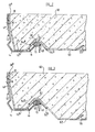
- FIGURE 2 is a section through a second assembly embodying the invention;
- FIGURE 3 is a section through a third assembly embodying the invention.
- Referring to Figure 1 of the drawings, a manhole cover and
frame assembly 10 comprises a rectangular cover 11 received within arectangular frame 12, theframe 12 being slightly larger than the cover 11. Theframe 12 comprises two perimeter pressedsteel side parts 12a each of substantially L-configuration in section, and two perimeter pressed steel end parts (not shown) of identical L-configuration in section, each part being cut to length, mitred at the ends to provide corners and welded to the other parts to produce a frame of desired size. The frame parts each have an inwardly extendinglimb 14 including ahorizontal portion 14a and a projectingridge 15 pressed upwardly therefrom, and a substantially verticalupstanding limb 16. - The
vertical limb 16 of theframe 12 has a cranked portion 17 which facilitates embedding theframe 12 in the ground over a sump, manhole or other access opening as concrete or other settable material is poured there around. - Received within the
frame 12 is the cover 11, the cover 11 similarly comprising two perimeter pressed steel side parts 18a each of substantially L-configuration in section, and two perimeter pressed steel end parts (not shown) also of identical L-configuration in section, each part being cut to length, mitred at the ends to provide corners and welded to the other parts to form arectangular cover perimeter 18 of desired size. Where a locking device is required to lock the cover 11 in theframe 12, asocket part 20, made as a generally cylindrical casting, is welded in one or more of the corners of thecover perimeter 18, or is engaged with the cover perimeter intermediate the ends of each side thereof, thesocket part 20 having arecess 22 with an upwardly facing abutment surface 24, and anaperture 25. - Received within the
recess 22 is thehead 30 of abolt 31 which comprises a first connecting element, theunderside 32 of thehead 30 of thebolt 31 engaging the upwardly facing abutment surface 24 of therecess 22. - The
head 30 of thebolt 31 has a plurality of slots, arranged in a crow's foot configuration, thebolt 31 being engageable by an axially extending spanner. Alternatively the bolt head may be of cheese head configuration having a hexagonal shaped recess to receive a tool of corresponding configuration, or of any other desired configuration. - The unusual head configuration discourages unauthorised removal of the cover 11 from the
frame 12. - The threaded
shank 36 of thebolt 31 extends downwardly through theaperture 25 of thesocket 20 and engages a second connecting element comprising a nut 40 which is held captive adjacent to theupper surface 41 of the upwardly extendinglimb 14 of theframe 12, by a cage C which has a tab T which prevents the nut 40 being removed from the cage C. Although the nut 40 could be welded to thesurface 41. - The
cover perimeter 18 is perforated as shown at 45 beneath theaperture 25 of thesocket part 20 to accommodate the cage C and the nut 40 whereby the cover 11 may be received within and locked into theframe 12 to prevent unauthorised removal. - Inwardly of the
perforation 45 is an upwardly facingridge 46 pressed upwardly from the inwardly extendinglimb 19 of thecover perimeter 18, which provides a recess 46a in the bottom surface of thelimb 19 and which corresponds with theridge 15 of theframe 12. In the recess 46a is aresilient sealing element 48 which comprises a diapolyprene sponge cord having acentral orifice 50. Alternatively, the sealingelement 48 may be made of any other suitable material such as natural rubber. As thebolt 31 is screwed into the nut 40, thesealing element 48 becomes increasingly compressed by theridge 15 between thecover perimeter 18 and theframe 12 thereby forming a seal therebetween. - The assembly shown in Figure 1 has a cover of light load-bearing capacity for pedestrian use, i.e. having a load bearing capacity of less than the equivalent of 3kN wheel loading as defined in British Standard 497 when applied to a grade A manhole cover or gully grating. The cover has a matrix of reinforcing
rods 52 which intersect across the width of the cover and are embedded inconcrete 60 or other settable material which is poured into the area bounded by thecover perimeter 18 during manufacture, and allowed to set. The ends 52a of therods 52 are welded as shown or adhered with suitable adhesive, or otherwise attached to theridge 46 of thecover perimeter 18. However if desired they could be cranked to the same or similar configuration to theridge 46 and looped over. In this case, therods 52 may not need to be otherwise attached also. - The nut 40 has two slots, one of which can be seen at 53 to-permit grit and deritis which, in use, may enter and foul the threads of the nut 40, to be easily washed away. If desired, only one, or more than two slots may be provided.
- Referring now to Figure 2, there is shown a section through an assembly having a cover of rectangular medium load-bearing capacity, i.e. having a load bearing capacity of up to the equivalent of 20kN wheel loading, intermediate the ends thereof. The
frame 12 is identical to that shown in Figure 1 as is thecover perimeter 18,the sockets 40 (not shown in Figure 2) being welded in the corners of thecover perimeter 18. However, in place of the matrix of reinforcingrods 52 which are embedded in the cast concrete, a reinforcingplate 50 is provided which extends across the entire area bounded by thecover perimeter 18. Theplate 50 has a periphery comprising a ridge 51 of corresponding configuration toridge 60 of thecover perimeter 18, thecover perimeter 18 andplate 50 being welded as shown at 54a and 54b, or adhered or otherwise attached together as necessary, to theridge 60. - The
plate 50 is shallow, i.e. it does not extend downwardly beyond theframe 12, although it can accommodate a greater volume of concrete than can the cover 11 shown in Figure 1, thereby providing a higher load-bearing capacity cover than the cover of the assembly of Figure 1. - A plurality of upwardly punched lugs 55 are provided in the
plate 50 to provide a key for the concrete or othersettable material 60 although if desired a plurality of lugs may be welded to the upper surface of theplate 50 instead of punched up outwardly therefrom as shown, or any other keying means may be provided if desired. - In all other respects, the assembly is of identical construction to that shown in Figure 1, like parts being designated by the same reference numerals.
- Figure 3 shows a section through a rectangular assembly having a heavy load-bearing capacity cover, i.e. having a load bearing capacity of up to the equivalent of 50KN wheel loading, similar to that shown in Figure 2, although the
shallow plate 50 is replaced by adeep plate 62 which has a similar ridge 61 to that shown at 51 in Figure 2. Theplate 62 extends downwardly beyond the frame into the manhole beneath and thus the cover can accommodate an even greater volume of concrete than the cover of the assembly shown in Figure 2. Again, upwardly punchedlugs 55 are provided to key the concrete in position. - If desired, reinforcing rods such as those shown at 52 in Figure 1 may be provided in addition to the
plate - It will be appreciated that during manufacture, it is possible to produce a plurality of assemblies of different size and configuration having covers of differing load-bearing capacity utilising frame and cover perimeter parts, the respective parts being of the same configuration, it only being necessary to cut the parts to different lengths, mitre the ends to provide corners and weld the parts together to produce assemblies of different size, and to use different reinforcing members such as the
shallow plate 50, ordeep plate 62 and/orrods 52, to produce a cover having a particular load-bearing capacity. - By utilising the invention it has been possible to provide a cover capable of withstanding loads the equivalent of 50kN wheel loading or above, due to the configuration of the cover, and the frame. In particular in each case the frame has a
horizontal part 14a on the inwardly extendinglimb 14, and the cover also has a horizontal portion H (which is cut away in Figure 1) which seats in theportion 14a of the frame. - In each assembly described above, it will be noted that the top of the cover 11 is at substantially the same level as the top of the
vertical limb 16 of the L-shapedframe 12. - Various modifications may be made to the assembly shown without departing from the scope of the invention. For example, the
cover perimeter 18 and/or theframe 12 may be made as castings instead of pressings. Further, although thevertical limb 16 of theframe 12 and vertical limb of thecover perimeter 18 are shown as being of substantially the same depth, if desired, these may be of different depths for different applications. - Further, the first connecting element need not comprise a bolt and the second connecting element a nut, but if desired any other co-operating connecting elements may be used. For example, the head of a bolt may be welded to the
surface 41 with the threaded shank extending upwardly, and the second connecting element comprises a nut received in therecess 22. - Further, a range of covers of load bearing capacity, from covers suitable for lightweight pedestrian use, to heavyweight loading use can economically be produced utilising the same frame and cover peramiter parts resulting in a large cost saving, where previous covers and frame assemblies of the kind specified have only been used for lightweight application and it has been necessary to produce conventional heavyweight cast iron covers and frames for heavy duty applications.
Claims (13)
1. A method of manufacturing a cover (11) for use in an assembly (10) of the kind specified comprising the steps of permanently connecting together a plurality of cover perimeter parts (18a) to provide a cover perimeter (18), each part (18a) being of substantially L configuration in section having, in use, an upstanding limb and an inwardly extending limb including a horizontal portion (H), selecting a reinforcing member or reinforcing members (50, 52, 62) to achieve a desired load-bearing capacity of the cover (11), locating the reinforcing member or members within the cover perimeter (18), engaging at least a part (52a, 51, 61) of the or each reinforcing member (50, 52, 62) with the inwardly extending limb (19) of the L-shaped cover perimeter (18), casting concrete (60) or other settable material into the area bounded by the cover perimeter (18) to cover at least part of the reinforcing member or members (50, 52, 62) and permitting the concrete (60) or other settable material to set.
2. A method according to Claim 1 wherein a lightweight cover of light load-bearing capacity is produced, having a matrix of elongate reinforcing members (52) which are embedded in the cast concrete (60) or other settable material.
3. A method according to Claim 1 wherein a medium load-bearing capacity cover is produced having a shallow plate reinforcing member (50) which, in use, does not extend downwardly beyond the frame (12), the shallow plate member (50) extending across substantially the entire area bounded by the cover perimeter (18).
4. A method according to Claim 1 wherein a high load-bearing capacity cover is produced by providing a deep plate reinforcing member (62), which, in use, extends downwardly below the frame (12), the deep plate member (62) extending across substantially the entire area bounded by the cover perimeter (18).
5. A method according to any one of the preceding claims wherein the inwardly extending limb (19) of the L-shaped cover perimeter has an upwardly projecting ridge (46) in the upper surface of the limb (19) thereby providing a corresponding recess (46a) in the lower surface of the limb (19), and the reinforcing member or members (50, 52, 62) are attached to the ridge (46).
6. A cover and frame assembly (10) of the kind specified the cover (11) having a socket part (20) with an upwardly facing abutment (24), a first connecting element (36) received within the socket (20) and engaged with said upwardly facing abutment (24), the cover (11) being perforated (45) beneath the socket part (20), the frame (11) having a second connecting element (40) captively associated with an upwardly facing part (41) of the frame (11), the second connecting element (40) being received within the perforation (45) of the cover (11) and the first (36) and second (40) connecting elements co-operating to connect the cover (11) to the frame (12).
7. An assembly according to Claim 6 wherein the cover (11) is made by a method according to any one of Claims 1 to 5.
8. An assembly according to Claim 7 wherein the socket part (20) is provided in a boss, engaged with the cover perimeter (18) prior to the concrete (60) or other settable material being cast and the boss is engaged in a corner of the cover perimeter (18) or along a side (ltia) of the cover perimeter (18).
9. An assembly according to any one of Claims 6 to 8 wherein the frame (12) comprises a plurality of frame parts (12a) permanently connected together, each part (12a) being of substantially L-configuration in section having, in use, an upstanding limb (16) and an inwardly extending limb (14) including a horizontal portion (14a), the horizontal portion (H) of the inwardly extending limb (19) of the cover, in use, resting directly or through an intermediate member, on the horizontal portion (14a) of the inwardly extending limb (14) of the frame (12).
10. An assembly according to Claim 9 wherein the inwardly extending limb (14) of the frame (12) has an upwardly projecting ridge (15) which locates in a recess (46a) in the horizontal limb (19) of the cover perimeter (18), when the cover (11) is received in the frame (12).
11. An assembly according to Claim 10 wherein a sealing member (48) is located in the recess (46a) of the cover perimeter (18) and is engaged by the ridge (15) of the frame (12) to provide a fluid tight seal therebetween.
12. An assembly according to any one of Claims 9 to 11 wherein the upstanding limb of the frame has an outwardly extending formation to facilitate embedding the frame in the ground.
13. An assembly according to any one of Claims 6 to 12 wherein the first connecting element (36) comprises a bolt and the second connecting element (40) a nut, the socket part (20) of the cover (11) is of such configuration that when the bolt (36) is removed therefrom, a lifting key may be inserted to facilitate lifting the cover (11) from the frame (12).
Applications Claiming Priority (2)
| Application Number | Priority Date | Filing Date | Title |
|---|---|---|---|
| GB8102058 | 1981-01-23 | ||
| GB8102058 | 1981-01-23 |
Publications (1)
| Publication Number | Publication Date |
|---|---|
| EP0057097A1 true EP0057097A1 (en) | 1982-08-04 |
Family
ID=10519164
Family Applications (1)
| Application Number | Title | Priority Date | Filing Date |
|---|---|---|---|
| EP19820300350 Ceased EP0057097A1 (en) | 1981-01-23 | 1982-01-25 | Improvements in or relating to cover and frame assemblies |
Country Status (1)
| Country | Link |
|---|---|
| EP (1) | EP0057097A1 (en) |
Cited By (3)
| Publication number | Priority date | Publication date | Assignee | Title |
|---|---|---|---|---|
| BE1008562A3 (en) * | 1993-01-15 | 1996-06-04 | Passavant Werke | Well recovery. |
| GB2318376A (en) * | 1996-09-20 | 1998-04-22 | Camas Uk Ltd | Duct cover assembly. |
| DE102008037929A1 (en) * | 2008-08-14 | 2010-02-18 | Lic Langmatz Gmbh | Manhole covering for tunnel shaft, has manhole cover fastened to supporting frame by screws and pressed on supporting element in mounted condition, where hollow chamber is pressed together with manhole cover |
Citations (2)
| Publication number | Priority date | Publication date | Assignee | Title |
|---|---|---|---|---|
| GB902650A (en) * | 1960-08-22 | 1962-08-09 | Broads Mfg Company Ltd | Improvements in manhole or like covers and frames |
| FR1425198A (en) * | 1964-02-25 | 1966-01-14 | Esser Kg Klaus | Shutter system for manholes |
-
1982
- 1982-01-25 EP EP19820300350 patent/EP0057097A1/en not_active Ceased
Patent Citations (2)
| Publication number | Priority date | Publication date | Assignee | Title |
|---|---|---|---|---|
| GB902650A (en) * | 1960-08-22 | 1962-08-09 | Broads Mfg Company Ltd | Improvements in manhole or like covers and frames |
| FR1425198A (en) * | 1964-02-25 | 1966-01-14 | Esser Kg Klaus | Shutter system for manholes |
Cited By (3)
| Publication number | Priority date | Publication date | Assignee | Title |
|---|---|---|---|---|
| BE1008562A3 (en) * | 1993-01-15 | 1996-06-04 | Passavant Werke | Well recovery. |
| GB2318376A (en) * | 1996-09-20 | 1998-04-22 | Camas Uk Ltd | Duct cover assembly. |
| DE102008037929A1 (en) * | 2008-08-14 | 2010-02-18 | Lic Langmatz Gmbh | Manhole covering for tunnel shaft, has manhole cover fastened to supporting frame by screws and pressed on supporting element in mounted condition, where hollow chamber is pressed together with manhole cover |
Similar Documents
| Publication | Publication Date | Title |
|---|---|---|
| US6558071B1 (en) | Pavement system | |
| DE69834062T2 (en) | Slotted insert with improved pull-out force | |
| US7879233B2 (en) | Drain grate filter assembly with compressible anchors | |
| US3943589A (en) | Gangway element | |
| EP1032294B1 (en) | Spillage control safety floor matting | |
| GB2092649A (en) | Manhole covers | |
| EP0057097A1 (en) | Improvements in or relating to cover and frame assemblies | |
| WO2005111318A1 (en) | Protective rib | |
| DE3508010C2 (en) | ||
| EP2896746A1 (en) | Drainage system | |
| GB2116611A (en) | Manhole frame and cover assembly | |
| KR20200094613A (en) | Grating auxiliary cover for easily attachment and separation | |
| EP2995723B1 (en) | Shaft cover frame | |
| DE3501821C2 (en) | Floor drain | |
| JP2889563B1 (en) | Construction manhole construction method | |
| JPH0676403U (en) | Filling frame material for grooves in grating | |
| JPH0220274Y2 (en) | ||
| DE10252185C5 (en) | Manhole cover or attachment | |
| KR100926167B1 (en) | Manufacturing method of the covering plate in road | |
| KR100843784B1 (en) | Drain board with a basement floor construction | |
| KR200333762Y1 (en) | Manhole structure | |
| KR830001196Y1 (en) | Landscaping Block Pour Mold | |
| JP6577776B2 (en) | Rainwater penetration | |
| KR20220041995A (en) | The Quiet Grating And Manhole | |
| EP0903445A1 (en) | Drainage grating for liquids in general, and associated support |
Legal Events
| Date | Code | Title | Description |
|---|---|---|---|
| PUAI | Public reference made under article 153(3) epc to a published international application that has entered the european phase |
Free format text: ORIGINAL CODE: 0009012 |
|
| AK | Designated contracting states |
Designated state(s): AT BE CH DE FR IT LI LU NL SE |
|
| 17P | Request for examination filed |
Effective date: 19820719 |
|
| RAP1 | Party data changed (applicant data changed or rights of an application transferred) |
Owner name: BRICKHOUSE DUDLEY MANUFACTURING LIMITED |
|
| STAA | Information on the status of an ep patent application or granted ep patent |
Free format text: STATUS: THE APPLICATION HAS BEEN REFUSED |
|
| 18R | Application refused |
Effective date: 19840922 |
|
| RIN1 | Information on inventor provided before grant (corrected) |
Inventor name: ROBINSON, GERALD Inventor name: ELMER, ANTHONY CHARLES |