EP0056984A1 - Phased antenna array - Google Patents
Phased antenna array Download PDFInfo
- Publication number
- EP0056984A1 EP0056984A1 EP82100406A EP82100406A EP0056984A1 EP 0056984 A1 EP0056984 A1 EP 0056984A1 EP 82100406 A EP82100406 A EP 82100406A EP 82100406 A EP82100406 A EP 82100406A EP 0056984 A1 EP0056984 A1 EP 0056984A1
- Authority
- EP
- European Patent Office
- Prior art keywords
- phase
- antenna
- individual
- radiator
- radiator elements
- Prior art date
- Legal status (The legal status is an assumption and is not a legal conclusion. Google has not performed a legal analysis and makes no representation as to the accuracy of the status listed.)
- Granted
Links
Images


Classifications
-
- H—ELECTRICITY
- H01—ELECTRIC ELEMENTS
- H01Q—ANTENNAS, i.e. RADIO AERIALS
- H01Q3/00—Arrangements for changing or varying the orientation or the shape of the directional pattern of the waves radiated from an antenna or antenna system
- H01Q3/26—Arrangements for changing or varying the orientation or the shape of the directional pattern of the waves radiated from an antenna or antenna system varying the relative phase or relative amplitude of energisation between two or more active radiating elements; varying the distribution of energy across a radiating aperture
- H01Q3/30—Arrangements for changing or varying the orientation or the shape of the directional pattern of the waves radiated from an antenna or antenna system varying the relative phase or relative amplitude of energisation between two or more active radiating elements; varying the distribution of energy across a radiating aperture varying the relative phase between the radiating elements of an array
- H01Q3/34—Arrangements for changing or varying the orientation or the shape of the directional pattern of the waves radiated from an antenna or antenna system varying the relative phase or relative amplitude of energisation between two or more active radiating elements; varying the distribution of energy across a radiating aperture varying the relative phase between the radiating elements of an array by electrical means
- H01Q3/36—Arrangements for changing or varying the orientation or the shape of the directional pattern of the waves radiated from an antenna or antenna system varying the relative phase or relative amplitude of energisation between two or more active radiating elements; varying the distribution of energy across a radiating aperture varying the relative phase between the radiating elements of an array by electrical means with variable phase-shifters
Definitions
- the present invention relates to a phase-controlled group antenna of the type specified in the preamble of patent claim 1.
- Such antennas are used advantageously in particular as radar antennas for airspace surveillance.
- ⁇ n is the size of the phase of the nth radiator element to be set
- sin ⁇ is the sine of the angle of the radiation direction ⁇ against the normal on the antenna surface
- x n is the coordinate of the antenna element in the direction parallel to the planes through normal and radiation direction is formed
- ⁇ o is the wavelength
- phase control In the case of radar antennas for airspace surveillance, it is also common to use the phase control not only for beam pivoting, but also for widening the antenna lobe (beam spoiling).
- the control phase ⁇ n becomes a second value added, which has the effect that the wave field excited by the antenna elements no longer has a flat phase front, but a curved phase front.
- a course of this club broadening phase proven proportional to the cosine of the distance from the antenna center D is the diameter of the group antenna in the x direction and x is measured from the center of the antenna area.
- the implementation of these widened antenna lobes often leads to unsatisfactory results, since the diagrams widened by the curvature of the phase front are sensitive to incorrect deviations in the amplitude of the antenna elements.
- the curvature of the phase front namely has the effect that the power radiated by the antenna surface is no longer preferably radiated only in one spatial direction, but rather that each antenna element preferably radiates in the direction of the perpendicular to the phase front at the respective location of the element.
- the course of the amplitude of the main lobe of the antenna pattern is approximately a replica of the A mplitudenverlaufs over the antenna surface.
- Line systems for feeding the antenna elements now often have tolerance-related or even systematic errors, in particular the serial feeds preferred because of their compactness, especially in the case of broadband use.
- the result of this is that the antenna lobes obtained are deformed, which in turn leads to incorrect directional determinations in the radar application.
- the object of the present invention is to provide a phase-controlled group antenna which eliminates the disruptive effects of the tolerance-related amplitude errors on the diagram without major additional outlay, without having to accept additional power losses.
- Claim 2 describes a particularly advantageous embodiment of the inventive concept.
- Claims 3 and 4 indicate favorable developments of the invention.
- the basis for the subsequent derivation of a relationship between the measured amplitude curve and setting values for the phase setting is the application of the geometric optics to the synthesis of antenna diagrams by designing the phase curve, as described for. B. usual for the calculation of reflector antennas and z. B. in S. Silver: Microwave Antenna Theory and Design, Mc.Graw Hill 1949, pp. 497 ff. Is described.
- the aim of this synthesis is to find the phase profile for a given distribution of the RF power over the antenna cross section P A (x), which causes this power to be radiated in the far field according to a desired distribution function P F (1 ⁇ ), ie an antenna diagram with the desired profile as a function of the directional angle ⁇ is achieved in the sectional planes considered. Because of the reciprocity, all versions also apply analogously to the receiving antenna.
- each zone of the antenna mainly radiates in a certain spatial direction
- the following assignment of the cross-sectional coordinates x to the angle ⁇ can be found from the energy conservation theorem D is the diameter of the antenna and ⁇ o the direction in which the desired radiation should begin.
- the distribution of the power over the antenna cross-section can be determined by measurement on the mounted antenna. Either they are measured at the inputs of the pathogens - in this case the integral is to be replaced by the sum of the power of the pathogens - or directly in front of the pathogens on a near-field measuring station.
- the mean power of a row of elements is to be taken in each case across the planes of the radiation direction under consideration.
- the desired power distribution in the far field depends on the application.
- a sector diagram is often required: However, because of the diffraction effects, this ideal desired diagram leads to implementations with an oscillating diagram. It is therefore advisable to choose a similar one instead of the ideal sector function (4), which does not show any sharp jumps. If the use of antennas does not require a different power distribution in the far field, a different desired diagram should be selected accordingly (e.g. cosecans in the square).
- a radiation direction ⁇ (x) can be assigned by numerically integrating (3) each coordinate value x on the antenna aperture.
- the phases you are looking for ⁇ (x) result from the fact that the radiation direction is perpendicular to the phase front, ie when the angle ⁇ is counted from the normal to the x direction, the derivation of the phase according to the coordinates x is equal to the tangent of the Angle ⁇
- the numerical integration of (5) provides the setting value for the control phase of the element at location x.
- phase values are stored as a constant in the computer used to control the phase shifter. If the radar system is operated in several frequencies and the radiation amplitudes of the elements change significantly over the frequency, the phase values for each frequency must be determined and saved separately.
- FIG. 1 shows an example of a linear group of dipoles (1-6) with the coordinates x I -x 6 , which are excited by a transmitter T via a feed line S.
- the phases ⁇ 1 - ⁇ 6 can be set by electronic phase shifters.
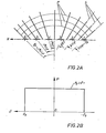
- FIG. 2A shows the optical beam path and curves of the same phase in front of the group antenna according to FIG. 1. Due to the phase setting, the antenna aperture A starts from a curved wavefront. The radiated power runs parallel to the optical beams S, which are perpendicular to the curves of the same phase P, in the spatial direction ⁇ . The angular position of the rays ⁇ (x) must be such that the power density per angular unit corresponds to the required profile P F ( ⁇ ). An example of such a desired power distribution in the far field, a sector diagram, is shown in FIG. 2B.
- FIG. 3A shows (in Cartesian representation) a cross section through a diagram of a serially fed group antenna without the correction according to the invention of the amplitude errors via the setting of the control phases.
- the asymmetrical diagram distortions are clearly recognizable, which can lead to considerable angle measurement errors when operating the antenna.
- FIG. 3B shows the diagram corrected using the concept of the invention on the same antenna.
Landscapes
- Variable-Direction Aerials And Aerial Arrays (AREA)
Abstract
Description
Die vorliegende Erfindung bezieht sich auf eine phasengesteuerte Gruppenantenne der im Oberbegriff des Patentanspruchs 1 angegebenen Art. Derartige Antennen finden insbesondere als Radarantennen für Luftraumüberwachung vorteilhafte Anwendung.The present invention relates to a phase-controlled group antenna of the type specified in the preamble of patent claim 1. Such antennas are used advantageously in particular as radar antennas for airspace surveillance.
Es ist bekannt, daß sich die Richtung der Antennenkeule von Gruppenantennen durch Veränderung der Phase der Antennenelemente trägheitslos verändern läßt. Bei einem ebenen oder linearen Array sind die Werte der Phasen der Ströme in den einzelnen Antennenelementen nach der folgenden bekannten Formel einzustellen:
Bei Radarantennen zur Luftraumüberwachung ist es darüber hinaus üblich, die Phasensteuerung nicht nur zur Strahlschwenkung, sondern auch zur Verbreiterung der Antennenkeule (beam spoiling) zu benutzen. Dabei wird der Steuerungsphase ϕn ein zweiter Wert ![]()
![]()

![]()
![]()
Eine Einschränkung der Toleranzen würde zu einem erheblichen Aufwand in der Entwicklung und Produktion solcher Speisungen führen. Eine nachträgliche Korrektur der Amplitudenwerte wäre nur durch zusätzliche Leistungsverluste zu erkaufen und ist schwierig zu realisieren.A limitation of the tolerances would lead to a considerable effort in the development and production of such feeds. A subsequent correction of the amplitude values could only be bought through additional power losses and is difficult to implement.
Aufgabe der vorliegenden Erfindung ist es, eine phasengesteuerte Gruppenantenne anzugeben, die ohne größeren zusätzlichen Aufwand die störenden Auswirkungen der toleranzbedingten Amplitudenfehler auf das Diagramm beseitigt, ohne zusätzliche Leistungsverluste in Kauf nehmen zu müssen.The object of the present invention is to provide a phase-controlled group antenna which eliminates the disruptive effects of the tolerance-related amplitude errors on the diagram without major additional outlay, without having to accept additional power losses.
Die erfindungsgemäße Lösung ist bei einer Antenne der im Oberbegriff des Patentanspruchs 1 beschriebenen Art durch die kennzeichnenden Merkmale des Patentanspruchs 1 gegeben.The solution according to the invention is given in an antenna of the type described in the preamble of claim 1 by the characterizing features of claim 1.
Anspruch 2 beschreibt eine besonders vorteilhafte Ausführung des Erfindungsgedankens. Die Ansprüche 3 und 4 geben günstige Weiterbildungen der Erfindung an.
Wesentlich an der Erfindung ist also die Kompensation der-Auswirkung der fehlerhaften Amplituden durch Einstellung der Steuerphasen nach Maßgabe der gemessenen Amplitudenverteilung. Nachdem die phasengesteuerte Gruppenantenne ohnehin über die dazu notwendigen Phasenschieber verfügt, ist für die erfindungsgemäße Antenne nur eine zusätzliche Funktion des zur Steuerung der Phasenschieber verwendeten Rechners (Beam Stearing Unit) nötig.What is essential to the invention is therefore the compensation of the effect of the faulty amplitudes by setting the control phases in accordance with the measured amplitude distribution. Since the phase-controlled group antenna already has the necessary phase shifters, only an additional function of the computer used to control the phase shifters (beam stearing unit) is required for the antenna according to the invention.
Im folgenden wird eine besonders vorteilhafte Ausführung des Erfindungsgedankens unter Bezugnahme- auf die Abbildungen eingehend beschrieben.A particularly advantageous embodiment of the inventive concept is described in detail below with reference to the figures.
Grundlage der nachfolgenden Herleitung einer Beziehung zwischen gemessenem Amplitudenverlauf und Einstellwerten für die Phaseneinstellung ist die Anwendung der geometrischen Optik auf die Synthese von Antennendiagrammen durch Gestaltung des Phasenverlaufs,wie sie z. B. für die Berechnung von Reflektorantennen üblich und z. B. in S. Silver: Mikrowave Antenna Theory and Design, Mc.Graw Hill 1949, pp. 497 ff. beschrieben ist.The basis for the subsequent derivation of a relationship between the measured amplitude curve and setting values for the phase setting is the application of the geometric optics to the synthesis of antenna diagrams by designing the phase curve, as described for. B. usual for the calculation of reflector antennas and z. B. in S. Silver: Microwave Antenna Theory and Design, Mc.Graw Hill 1949, pp. 497 ff. Is described.
Ziel dieser Synthese ist es, zu einer gegebenen Verteilung der HF-Leistung über den Antennenquerschnitt PA (x) den Phasenverlauf zu finden, der bewirkt, daß diese Leistung gemäß einer gewünschten Verteilungsfunktion PF (1ϑ) im Fernfeld abgestrahlt wird, d. h., daß in den betrachteten Schnittebenen ein Antennendiagramm mit gewünschtem Verlauf in Abhängigkeit zum Richtungswinkel ϑ erzielt wird. Wegen der Reziprozität gelten grundsätzlich alle Ausführungen auch analog für die Empfangsantenne.The aim of this synthesis is to find the phase profile for a given distribution of the RF power over the antenna cross section P A (x), which causes this power to be radiated in the far field according to a desired distribution function P F (1ϑ), ie an antenna diagram with the desired profile as a function of the directional angle ϑ is achieved in the sectional planes considered. Because of the reciprocity, all versions also apply analogously to the receiving antenna.
Da, wie bereits dargelegt, bei diesem Verfahren der Diagrammsynthese jede Zone der Antenne hauptsächlich in eine bestimmte Raumrichtung strahlt, kann aus dem Energieerhaltungssatz folgende Zuordnung der Querschnittskoordinaten x zum Winkel ϑ gefunden werden
Falls es sich nicht um eine lineare Antennengruppe, sondern um ein zweidimensionales Array handelt, ist jeweils die mittlere Leistung einer Zeile von Elementen quer zu Ebenen der betrachteten Abstrahlrichtung zu nehmen.If it is not a linear antenna group, but a two-dimensional array, the mean power of a row of elements is to be taken in each case across the planes of the radiation direction under consideration.
Die gewünschte Leistungsverteilung im Fernfeld hängt vom Anwendungszweck ab. Vielfach wird ein Sektordiagramm gefordert:
Sind beide Funktionen PA und PF gegeben, so läßt sich durch numerische Integration von (3) jedem Koordinatenwert x auf der Antennenapertur eine Abstrahlrichtung ϑ(x) zuordnen. Die gesuchten Phasen![]()


![]()
Diese Phasenwerte werden in dem zur Steuerung des Phasenschiebers verwendeten Rechner als Konstante gespeichert. Soweit die Radaranlage in mehreren Frequenzen betrieben wird und die Strahlungsamplituden der Elemente sich über die Frequenz erheblich ändern, sind die Phasenwerte für jede Frequenz gesondert zu bestimmen und abzuspeichern.These phase values are stored as a constant in the computer used to control the phase shifter. If the radar system is operated in several frequencies and the radiation amplitudes of the elements change significantly over the frequency, the phase values for each frequency must be determined and saved separately.
FIG. 1 zeigt ein Beispiel für eine lineare Gruppe von Dipolen (1-6) mit den Koordinaten xI-x6, die von einem Sender T über eine Speiseleitung S angeregt werden. Die Phasen ϕ1-ϕ6 können durch elektronische Phasenschieber eingestellt werden. Vor den Dipolen ergibt sich eine Verteilung der HF-Leistung P (x), die z. B. mit einem Testempfänger R gemessen werden kann.FIG. 1 shows an example of a linear group of dipoles (1-6) with the coordinates x I -x 6 , which are excited by a transmitter T via a feed line S. The phases ϕ 1 -ϕ 6 can be set by electronic phase shifters. In front of the dipoles there is a distribution of the RF power P (x), which, for. B. can be measured with a test receiver R.
FIG. 2A zeigt den optischen Strahlengang und Kurven gleicher Phase vor der Gruppenantenne nach FIG. 1. Durch die Phaseneinstellung geht von der Antennenapertur A eine gekrümmte Wellenfront aus. Die abgestrahlte Leistung verläuft parallel zu den optischen Strahlen S,die senkrecht auf den Kurven gleicher Phase P stehen, in die Raumrichtung ϑ. Die Winkellage der Strahlen ϑ(x) hat so zu erfolgen, daß die Leistungsdichte pro Winkeleinheit dem geforderten Verlauf PF(ϑ) entspricht. Ein Beispiel für eine solche gewünschte Leistungsverteilung im Fernfeld, ein Sektordiagramm, ist in FIG. 2B dargestellt.FIG. 2A shows the optical beam path and curves of the same phase in front of the group antenna according to FIG. 1. Due to the phase setting, the antenna aperture A starts from a curved wavefront. The radiated power runs parallel to the optical beams S, which are perpendicular to the curves of the same phase P, in the spatial direction ϑ. The angular position of the rays ϑ (x) must be such that the power density per angular unit corresponds to the required profile P F (ϑ). An example of such a desired power distribution in the far field, a sector diagram, is shown in FIG. 2B.
Die FIG. 3A zeigt (in kartesischer Darstellung) einen Querschnitt durch ein Diagramm einer seriell gespeisten Gruppenantenne ohne die erfindungsgemäße Korrektur der Amplitudenfehler über die Einstellung der Steuerphasen. Deutlich erkennbar sind die assymetrischen Diagrammverzerrungen, die beim Betrieb der Antenne zu beträchtlichen Winkelmeßfehlern führen können. FIG. 3B zeigt demgegenüber das unter Anwendung des Erfindungsgedankens auf dieselbe Antenne korrigierte Diagramm.The FIG. 3A shows (in Cartesian representation) a cross section through a diagram of a serially fed group antenna without the correction according to the invention of the amplitude errors via the setting of the control phases. The asymmetrical diagram distortions are clearly recognizable, which can lead to considerable angle measurement errors when operating the antenna. FIG. 3B, on the other hand, shows the diagram corrected using the concept of the invention on the same antenna.
Claims (4)


Applications Claiming Priority (2)
| Application Number | Priority Date | Filing Date | Title |
|---|---|---|---|
| DE3102110A DE3102110A1 (en) | 1981-01-23 | 1981-01-23 | PHASE CONTROLLED GROUP ANTENNA |
| DE3102110 | 1981-01-23 |
Publications (2)
| Publication Number | Publication Date |
|---|---|
| EP0056984A1 true EP0056984A1 (en) | 1982-08-04 |
| EP0056984B1 EP0056984B1 (en) | 1985-11-06 |
Family
ID=6123176
Family Applications (1)
| Application Number | Title | Priority Date | Filing Date |
|---|---|---|---|
| EP82100406A Expired EP0056984B1 (en) | 1981-01-23 | 1982-01-21 | Phased antenna array |
Country Status (2)
| Country | Link |
|---|---|
| EP (1) | EP0056984B1 (en) |
| DE (2) | DE3102110A1 (en) |
Citations (7)
| Publication number | Priority date | Publication date | Assignee | Title |
|---|---|---|---|---|
| DE2110231A1 (en) * | 1971-03-04 | 1972-09-14 | Licentia Gmbh | Antenna system |
| DE2113856A1 (en) * | 1970-08-12 | 1972-09-28 | Licentia Gmbh | Directional antenna with adjustable radiation pattern |
| GB1353617A (en) * | 1970-08-22 | 1974-05-22 | Emi Ltd | Electronically steered aerial arrays |
| US3903524A (en) * | 1973-05-25 | 1975-09-02 | Hazeltine Corp | Antenna system using variable phase pattern synthesis |
| DE2612148A1 (en) * | 1976-03-23 | 1977-10-06 | Siemens Ag | Phase calculating circuit for lobe swinging radar antenna - has control data generator between central computer and phase calculator |
| DE2612147A1 (en) * | 1976-03-23 | 1977-10-06 | Siemens Ag | Phase deflection aerial array - adds wanted focussing phase from memory to computed direction phase to control phase shifters |
| US4253098A (en) * | 1978-10-26 | 1981-02-24 | The Marconi Company Limited | Radar systems |
-
1981
- 1981-01-23 DE DE3102110A patent/DE3102110A1/en not_active Withdrawn
-
1982
- 1982-01-21 DE DE8282100406T patent/DE3267204D1/en not_active Expired
- 1982-01-21 EP EP82100406A patent/EP0056984B1/en not_active Expired
Patent Citations (7)
| Publication number | Priority date | Publication date | Assignee | Title |
|---|---|---|---|---|
| DE2113856A1 (en) * | 1970-08-12 | 1972-09-28 | Licentia Gmbh | Directional antenna with adjustable radiation pattern |
| GB1353617A (en) * | 1970-08-22 | 1974-05-22 | Emi Ltd | Electronically steered aerial arrays |
| DE2110231A1 (en) * | 1971-03-04 | 1972-09-14 | Licentia Gmbh | Antenna system |
| US3903524A (en) * | 1973-05-25 | 1975-09-02 | Hazeltine Corp | Antenna system using variable phase pattern synthesis |
| DE2612148A1 (en) * | 1976-03-23 | 1977-10-06 | Siemens Ag | Phase calculating circuit for lobe swinging radar antenna - has control data generator between central computer and phase calculator |
| DE2612147A1 (en) * | 1976-03-23 | 1977-10-06 | Siemens Ag | Phase deflection aerial array - adds wanted focussing phase from memory to computed direction phase to control phase shifters |
| US4253098A (en) * | 1978-10-26 | 1981-02-24 | The Marconi Company Limited | Radar systems |
Also Published As
| Publication number | Publication date |
|---|---|
| DE3102110A1 (en) | 1982-08-19 |
| EP0056984B1 (en) | 1985-11-06 |
| DE3267204D1 (en) | 1985-12-12 |
Similar Documents
| Publication | Publication Date | Title |
|---|---|---|
| DE102011088045B4 (en) | Phased array antenna and phase calibration method | |
| DE69933145T2 (en) | Calibration for an adaptive array antenna | |
| DE19648203C2 (en) | Multi-beam automotive radar system | |
| DE112006003644B4 (en) | radar device | |
| DE102011088046B4 (en) | Phased array antenna and phase calibration method | |
| EP1532716B1 (en) | Calibration device for an antenna array and method for calibrating said array | |
| EP3039444B1 (en) | Radar sensor for motor vehicles | |
| DE112019006800T5 (en) | Antenna device and radar device | |
| DE3934155A1 (en) | PHASE CONTROLLED ANTENNA ARRANGEMENT | |
| DE102018207718A1 (en) | Method for phase calibration of high-frequency components of a radar sensor | |
| DE102018212147A1 (en) | RADAR DEVICE | |
| DE102018210070A1 (en) | Procedure for calibrating a MIMO radar sensor for motor vehicles | |
| DE102019120460A1 (en) | HIKING WAVE IMAGE DISTRIBUTOR FOR A HIGH-RESOLUTION RADAR SYSTEM | |
| DE2244724A1 (en) | CONTROL DEVICE FOR AN ANTENNA LINE FOR GENERATING ELECTRONICALLY SWIVELING RADIATION DIAGRAMS | |
| EP3467450A1 (en) | Radar fill level measuring device with a radar system on chip | |
| EP2616840A1 (en) | Radar sensor for motor vehicles, especially lca sensor | |
| DE69625949T2 (en) | Group antenna device | |
| EP2862235A1 (en) | Antenna arrangement and method | |
| EP1476921B1 (en) | Device for emitting and receiving electromagnetic radiation | |
| EP0056984B1 (en) | Phased antenna array | |
| EP0935825B1 (en) | Radar sensor for a vehicle | |
| DE102005011128A1 (en) | Electronically controllable antenna e.g. planar patch antenna, for transceiver in airplane, has sensors directly arranged in reactive near field of emitter units to measure and calibrate amplitude and/or phase of units | |
| DE10238588B4 (en) | Mirror surface precision measuring device and mirror surface control system of a reflector antenna | |
| EP0023606B1 (en) | Antenna system for locating the position of a microwave signal source | |
| DE2226435A1 (en) | Radio interferometer |
Legal Events
| Date | Code | Title | Description |
|---|---|---|---|
| PUAI | Public reference made under article 153(3) epc to a published international application that has entered the european phase |
Free format text: ORIGINAL CODE: 0009012 |
|
| AK | Designated contracting states |
Designated state(s): CH DE FR GB IT NL |
|
| 17P | Request for examination filed |
Effective date: 19830119 |
|
| ITF | It: translation for a ep patent filed |
Owner name: BARZANO' E ZANARDO MILANO S.P.A. |
|
| GRAA | (expected) grant |
Free format text: ORIGINAL CODE: 0009210 |
|
| AK | Designated contracting states |
Designated state(s): CH DE FR GB IT LI NL |
|
| REF | Corresponds to: |
Ref document number: 3267204 Country of ref document: DE Date of ref document: 19851212 |
|
| ET | Fr: translation filed | ||
| PLBE | No opposition filed within time limit |
Free format text: ORIGINAL CODE: 0009261 |
|
| STAA | Information on the status of an ep patent application or granted ep patent |
Free format text: STATUS: NO OPPOSITION FILED WITHIN TIME LIMIT |
|
| 26N | No opposition filed | ||
| ITTA | It: last paid annual fee | ||
| REG | Reference to a national code |
Ref country code: CH Ref legal event code: PUE Owner name: TELEFUNKEN SYSTEMTECHNIK GMBH |
|
| NLS | Nl: assignments of ep-patents |
Owner name: TELEFUNKEN SYSTEMTECHNIK GMBH TE ULM A.D. DONAU, B |
|
| ITPR | It: changes in ownership of a european patent |
Owner name: CESSIONE;TELEFUNKEN SYSTEMTECHNIK GMBH |
|
| REG | Reference to a national code |
Ref country code: GB Ref legal event code: 732 |
|
| REG | Reference to a national code |
Ref country code: FR Ref legal event code: TP |
|
| PGFP | Annual fee paid to national office [announced via postgrant information from national office to epo] |
Ref country code: CH Payment date: 19940121 Year of fee payment: 13 |
|
| PGFP | Annual fee paid to national office [announced via postgrant information from national office to epo] |
Ref country code: NL Payment date: 19940131 Year of fee payment: 13 |
|
| PG25 | Lapsed in a contracting state [announced via postgrant information from national office to epo] |
Ref country code: LI Effective date: 19950131 Ref country code: CH Effective date: 19950131 |
|
| PG25 | Lapsed in a contracting state [announced via postgrant information from national office to epo] |
Ref country code: NL Effective date: 19950801 |
|
| REG | Reference to a national code |
Ref country code: CH Ref legal event code: PL |
|
| NLV4 | Nl: lapsed or anulled due to non-payment of the annual fee |
Effective date: 19950801 |
|
| PGFP | Annual fee paid to national office [announced via postgrant information from national office to epo] |
Ref country code: GB Payment date: 19990115 Year of fee payment: 18 |
|
| PGFP | Annual fee paid to national office [announced via postgrant information from national office to epo] |
Ref country code: FR Payment date: 19990129 Year of fee payment: 18 |
|
| PGFP | Annual fee paid to national office [announced via postgrant information from national office to epo] |
Ref country code: DE Payment date: 19990317 Year of fee payment: 18 |
|
| PG25 | Lapsed in a contracting state [announced via postgrant information from national office to epo] |
Ref country code: GB Free format text: LAPSE BECAUSE OF NON-PAYMENT OF DUE FEES Effective date: 20000121 |
|
| GBPC | Gb: european patent ceased through non-payment of renewal fee |
Effective date: 20000121 |
|
| PG25 | Lapsed in a contracting state [announced via postgrant information from national office to epo] |
Ref country code: FR Free format text: LAPSE BECAUSE OF NON-PAYMENT OF DUE FEES Effective date: 20000929 |
|
| PG25 | Lapsed in a contracting state [announced via postgrant information from national office to epo] |
Ref country code: DE Free format text: LAPSE BECAUSE OF NON-PAYMENT OF DUE FEES Effective date: 20001101 |
|
| REG | Reference to a national code |
Ref country code: FR Ref legal event code: ST |