EP0056773B1 - Continuously charged electric-arc furnace for melting scrap - Google Patents
Continuously charged electric-arc furnace for melting scrap Download PDFInfo
- Publication number
- EP0056773B1 EP0056773B1 EP19820400101 EP82400101A EP0056773B1 EP 0056773 B1 EP0056773 B1 EP 0056773B1 EP 19820400101 EP19820400101 EP 19820400101 EP 82400101 A EP82400101 A EP 82400101A EP 0056773 B1 EP0056773 B1 EP 0056773B1
- Authority
- EP
- European Patent Office
- Prior art keywords
- scrap
- hearth
- furnace
- pile
- iron
- Prior art date
- Legal status (The legal status is an assumption and is not a legal conclusion. Google has not performed a legal analysis and makes no representation as to the accuracy of the status listed.)
- Expired
Links
Images
Classifications
-
- C—CHEMISTRY; METALLURGY
- C21—METALLURGY OF IRON
- C21C—PROCESSING OF PIG-IRON, e.g. REFINING, MANUFACTURE OF WROUGHT-IRON OR STEEL; TREATMENT IN MOLTEN STATE OF FERROUS ALLOYS
- C21C5/00—Manufacture of carbon-steel, e.g. plain mild steel, medium carbon steel or cast steel or stainless steel
- C21C5/52—Manufacture of steel in electric furnaces
- C21C5/527—Charging of the electric furnace
-
- F—MECHANICAL ENGINEERING; LIGHTING; HEATING; WEAPONS; BLASTING
- F27—FURNACES; KILNS; OVENS; RETORTS
- F27B—FURNACES, KILNS, OVENS, OR RETORTS IN GENERAL; OPEN SINTERING OR LIKE APPARATUS
- F27B3/00—Hearth-type furnaces, e.g. of reverberatory type; Tank furnaces
- F27B3/10—Details, accessories, or equipment peculiar to hearth-type furnaces
- F27B3/18—Arrangements of devices for charging
-
- F—MECHANICAL ENGINEERING; LIGHTING; HEATING; WEAPONS; BLASTING
- F27—FURNACES; KILNS; OVENS; RETORTS
- F27B—FURNACES, KILNS, OVENS, OR RETORTS IN GENERAL; OPEN SINTERING OR LIKE APPARATUS
- F27B3/00—Hearth-type furnaces, e.g. of reverberatory type; Tank furnaces
- F27B3/08—Hearth-type furnaces, e.g. of reverberatory type; Tank furnaces heated electrically, with or without any other source of heat
- F27B3/085—Arc furnaces
-
- F—MECHANICAL ENGINEERING; LIGHTING; HEATING; WEAPONS; BLASTING
- F27—FURNACES; KILNS; OVENS; RETORTS
- F27D—DETAILS OR ACCESSORIES OF FURNACES, KILNS, OVENS, OR RETORTS, IN SO FAR AS THEY ARE OF KINDS OCCURRING IN MORE THAN ONE KIND OF FURNACE
- F27D3/00—Charging; Discharging; Manipulation of charge
- F27D2003/0034—Means for moving, conveying, transporting the charge in the furnace or in the charging facilities
- F27D2003/0039—Means for moving, conveying, transporting the charge in the furnace or in the charging facilities comprising magnetic means
- F27D2003/004—Magnetic lifters
-
- F—MECHANICAL ENGINEERING; LIGHTING; HEATING; WEAPONS; BLASTING
- F27—FURNACES; KILNS; OVENS; RETORTS
- F27D—DETAILS OR ACCESSORIES OF FURNACES, KILNS, OVENS, OR RETORTS, IN SO FAR AS THEY ARE OF KINDS OCCURRING IN MORE THAN ONE KIND OF FURNACE
- F27D3/00—Charging; Discharging; Manipulation of charge
- F27D3/12—Travelling or movable supports or containers for the charge
- F27D2003/125—Charging cars, lift trolleys
- F27D2003/127—Charging cars, lift trolleys for carrying pots
-
- F—MECHANICAL ENGINEERING; LIGHTING; HEATING; WEAPONS; BLASTING
- F27—FURNACES; KILNS; OVENS; RETORTS
- F27D—DETAILS OR ACCESSORIES OF FURNACES, KILNS, OVENS, OR RETORTS, IN SO FAR AS THEY ARE OF KINDS OCCURRING IN MORE THAN ONE KIND OF FURNACE
- F27D3/00—Charging; Discharging; Manipulation of charge
- F27D3/0025—Charging or loading melting furnaces with material in the solid state
- F27D3/003—Charging laterally, e.g. with a charging box
-
- F—MECHANICAL ENGINEERING; LIGHTING; HEATING; WEAPONS; BLASTING
- F27—FURNACES; KILNS; OVENS; RETORTS
- F27D—DETAILS OR ACCESSORIES OF FURNACES, KILNS, OVENS, OR RETORTS, IN SO FAR AS THEY ARE OF KINDS OCCURRING IN MORE THAN ONE KIND OF FURNACE
- F27D3/00—Charging; Discharging; Manipulation of charge
- F27D3/04—Ram or pusher apparatus
-
- F—MECHANICAL ENGINEERING; LIGHTING; HEATING; WEAPONS; BLASTING
- F27—FURNACES; KILNS; OVENS; RETORTS
- F27D—DETAILS OR ACCESSORIES OF FURNACES, KILNS, OVENS, OR RETORTS, IN SO FAR AS THEY ARE OF KINDS OCCURRING IN MORE THAN ONE KIND OF FURNACE
- F27D3/00—Charging; Discharging; Manipulation of charge
- F27D3/15—Tapping equipment; Equipment for removing or retaining slag
- F27D3/1509—Tapping equipment
-
- Y—GENERAL TAGGING OF NEW TECHNOLOGICAL DEVELOPMENTS; GENERAL TAGGING OF CROSS-SECTIONAL TECHNOLOGIES SPANNING OVER SEVERAL SECTIONS OF THE IPC; TECHNICAL SUBJECTS COVERED BY FORMER USPC CROSS-REFERENCE ART COLLECTIONS [XRACs] AND DIGESTS
- Y02—TECHNOLOGIES OR APPLICATIONS FOR MITIGATION OR ADAPTATION AGAINST CLIMATE CHANGE
- Y02P—CLIMATE CHANGE MITIGATION TECHNOLOGIES IN THE PRODUCTION OR PROCESSING OF GOODS
- Y02P10/00—Technologies related to metal processing
- Y02P10/20—Recycling
Definitions
- the present invention relates to an electric arc furnace allowing energy saving and furthermore capable of continuously melting all-scrap scrap, such as is found on the market and whose length can go up to four meters or more.
- Electric ovens are known, such as for example that described in patent FR-A-2 065 880, which can be supplied continuously by short scrap or iron sponges. Such ovens use small diameter loading openings located in the roof of the oven, and obviously can not operate with large scrap.
- Electric arc furnaces are also known for reducing ores, as described in patent FR-A-1 447 922, one of the side walls of the enclosure of which is pierced, at a level situated above the sole, of an ore supply tunnel.
- the ore is contained in a well, connected to the interior enclosure of the furnace by said tunnel, which is at the same level as the base of the well, and this ore is pushed into the furnace through this tunnel by several pistons operating alternately.
- the electric furnace of the invention has the advantage of being able to be supplied continuously with scrap metal of large dimensions. It also makes it possible, whatever the size of the scrap, to recover the heat of the smoke, thereby reducing the electrical energy required for melting.
- It is of the type comprising a hearth intended to receive the molten metal, fixed in position, and an interior enclosure defining with the hearth the laboratory of the furnace, the corresponding part of the enclosure constituting the roof of the furnace, and it is characterized in that that said inner enclosure further defines with a floor, laterally adjacent to the floor and located higher than it so that it is contiguous to the outer edge of the floor, a lateral space intended for the storage of scrap metal, in that said lateral space occupies a volume at least equal to a third of the volume occupied by the interior space of the oven, in that said lateral space is equipped with an opening, of the hatch or door type, located at its upper part and allowing the '' supplied by cold scrap intended to rest in the form of a pile on said floor, in that it is
- the upper end of the lateral space is located above the roof of the oven.
- the electric oven of the invention which is a stationary oven and which comprises a conventional hearth 1 made of refractory material provided with a evacuation of liquid steel to a pocket 3 constituted by a conventional nozzle nozzle 2, has its inner enclosure produced in a very particular way, because defining, beside the floor 1 and with the floor 9, a lateral space 4 of fairly large volume intended for prior storage of cold scrap before their introduction into the melting zone, that is to say on the floor 1, where the electric arcs coming from the electrodes 5 act.
- the lateral space 4 has a large volume, for example of the order of a good third of the entire volume of the interior enclosure of the oven, so that on the one hand can easily introduce large scrap metal and on the other hand we can store a large volume of scrap, this lateral space 4 being connected to the pipe 16 for evacuating smoke from the oven, so as to be crossed by said fumes, which makes it possible to take full advantage of the particular advantage of the invention which consists in recovering the heat of the fumes in order to preheat the scrap before they are introduced into the melting zone.
- the lateral space 4 of the invention has a significant height, of the order of two to three times that of the central part 6 of the roof 7 of the oven by example, which allows, as will be seen below, a particularly advantageous implementation of the invention, on the one hand because it makes it possible to easily supply the space 4 with cold scrap using '' a hatch or door 8 placed at the top of said space, and on the other hand because it makes it possible to take advantage of the optimum preheating of the scrap due to the fumes of the fact that it is possible to feed the sole with the scrap located at the bottom of the pile 10 stored in the lateral space 4, that is to say the hottest because located closest to the active area of the sole, and because having stayed longer in the lateral space 4 than the scrap found at the top of said pile 10.
- the internal enclosure of the oven has, due to the presence of the lateral space 4 of the invention, a tormented shape, which would be very difficult to achieve.
- refractory material apart from sole 1 and zone 6 made of refractory material and apart from most of the floor 9 of the lateral space 4 made in the form of a massive construction and inclined towards the sole as shown in Figure 1, the walls and the top of the oven are metallic and include, in the warmer parts, zones cooled by circulation of water, or other fluid, this technique is now common in the construction of the walls of electric ovens.
- a steel block 11 serving as a pusher and actuated by a jack 12 is placed , in its retracted position as shown in Figure 1, on the part of the inclined floor 9 which is external to the oven enclosure.
- the pusher unit 11a in the retracted position, advantageously its front edge situated at the limit or outside of the lateral space 4, so as not to hinder the formation of the pile 10.
- FIG. 1 shows the phase of introduction, into the lateral space 4 of the invention, of a portion 13 of cold scrap added to the pile 10 of already preheated scrap that said space 4 contains.
- the door 8 was opened, by tilting upwards, and the said portion of the door is then pushed, using a dozer. cold scrap inside the lateral space 4 where it falls on top of the pile 10.
- the pusher 11 is advanced forward, by output from the rod of the jack 12, which has the effect, as can be clearly seen in the drawing, of introducing , in the laboratory delimited by sole 1, only the lower part of the scrap pile 10, which is the warmest part not only because it is located closest to the zone of maximum radiation, but also because it stayed the longest in the lateral space 4, as can be seen on examining FIGS. 1 and 2, and was traversed by the fumes sucked in by the exhaust pipe 16.
Landscapes
- Engineering & Computer Science (AREA)
- Chemical & Material Sciences (AREA)
- Metallurgy (AREA)
- Manufacturing & Machinery (AREA)
- General Engineering & Computer Science (AREA)
- Materials Engineering (AREA)
- Mechanical Engineering (AREA)
- Organic Chemistry (AREA)
- Vertical, Hearth, Or Arc Furnaces (AREA)
- Furnace Details (AREA)
- Furnace Charging Or Discharging (AREA)
- Manufacture And Refinement Of Metals (AREA)
- Processing And Handling Of Plastics And Other Materials For Molding In General (AREA)
- Waste-Gas Treatment And Other Accessory Devices For Furnaces (AREA)
Abstract
Description
La présente invention se rapporte à un four électrique à arcs permettant une économie d'énergie et en outre apte à fondre en continu de la ferraille tout-venant, telle qu'on la trouve dans le commerce et dont la longueur peut aller jusqu'à quatre mètres et plus.The present invention relates to an electric arc furnace allowing energy saving and furthermore capable of continuously melting all-scrap scrap, such as is found on the market and whose length can go up to four meters or more.
On connaît des fours électriques, tel que par exemple celui décrit dans le brevet FR-A-2 065 880, qui peuvent être alimentés en continu par des ferrailles courtes ou des éponges de fer. De tels fours utilisent des ouvertures de chargement de faible diamètre situées dans la voûte du four, et ne peuvent évidemment pas fonctionner avec des ferrailles de grandes dimensions.Electric ovens are known, such as for example that described in patent FR-A-2 065 880, which can be supplied continuously by short scrap or iron sponges. Such ovens use small diameter loading openings located in the roof of the oven, and obviously can not operate with large scrap.
On connaît par ailleurs des fours électriques à arcs destinés à la réduction de minerais, tels que décrits dans le brevet FR-A-1 447 922, dont une des parois latérales de l'enceinte est percée, à un niveau situé au-dessus de la sole, d'un tunnel d'alimentation en minerai. Dans ce dispositif, le minerai est contenu dans un puits, relié à l'enceinte intérieure du four par ledit tunnel, qui se trouve au même niveau que la base du puits, et ce minerai est poussé dans le four à travers ce tunnel par plusieurs pistons fonctionnant alternativement.Electric arc furnaces are also known for reducing ores, as described in patent FR-A-1 447 922, one of the side walls of the enclosure of which is pierced, at a level situated above the sole, of an ore supply tunnel. In this device, the ore is contained in a well, connected to the interior enclosure of the furnace by said tunnel, which is at the same level as the base of the well, and this ore is pushed into the furnace through this tunnel by several pistons operating alternately.
Le four électrique de l'invention présente l'avantage de pouvoir être alimenté en continu avec des ferrailles de grandes dimensions. Il permet par ailleurs, quelles que soient les dimensions des ferrailles, une récupération de la chaleur des fumées permettant de réduire l'énergie électrique nécessaire à la fusion. Il est du type comportant une sole destinée à recevoir le métal fondu, fixe en position, et une enceinte intérieure définissant avec la sole le laboratoire du four, la partie correspondante de l'enceinte constituant la voûte du four, et il est caractérisé en ce que ladite enceinte intérieure définit en outre avec un plancher, adjacent latéralement à la sole et situé plus haut qu'elle de telle manière qu'il soit contigü au bord extérieur de la sole, un espace latéral destiné au stockage des ferrailles, en ce que ledit espace latéral occupe un volume au moins égal au tiers du volume occupé par l'espace intérieur du four, en ce que ledit espace latéral est équipé d'une ouverture, du genre trappe ou porte, situé à sa partie supérieure et permettant de l'alimenter par des ferrailles froides destinées à reposer sous forme d'un tas sur ledit plancher, en ce qu'il est équipé d'un dispositif permettant de pousser vers la sole la base dudit tas de ferrailles, et en ce que la conduite d'évacuation des fumées du four a son point de départ sur une paroi dudit espace séparée de la sole par le tas de ferrailles emmagasiné sur le plancher dudit espace latéral, de façon à ce que ledit tas de ferrailles soit traversé par lesdites fumées.The electric furnace of the invention has the advantage of being able to be supplied continuously with scrap metal of large dimensions. It also makes it possible, whatever the size of the scrap, to recover the heat of the smoke, thereby reducing the electrical energy required for melting. It is of the type comprising a hearth intended to receive the molten metal, fixed in position, and an interior enclosure defining with the hearth the laboratory of the furnace, the corresponding part of the enclosure constituting the roof of the furnace, and it is characterized in that that said inner enclosure further defines with a floor, laterally adjacent to the floor and located higher than it so that it is contiguous to the outer edge of the floor, a lateral space intended for the storage of scrap metal, in that said lateral space occupies a volume at least equal to a third of the volume occupied by the interior space of the oven, in that said lateral space is equipped with an opening, of the hatch or door type, located at its upper part and allowing the '' supplied by cold scrap intended to rest in the form of a pile on said floor, in that it is equipped with a device making it possible to push the base of said pile of scrap towards the sole, and in that the pipe d '' evacuation n smoke from the oven has its starting point on a wall of said space separated from the hearth by the pile of scrap stored on the floor of said lateral space, so that said pile of scrap is crossed by said smoke.
De préférence l'extrémité supérieure de l'espace latéral est située au-dessus de la voûte du four.Preferably the upper end of the lateral space is located above the roof of the oven.
L'invention sera mieux comprise à l'aide de la description suivante d'un example de réalisation, en référence aux dessins annexés dans lesquels:
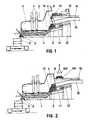
- - la figure 1 est une vue latérale très schématique du dispositif de l'invention, montrant l'introduction de ferrailles froides dans l'enceinte du four
- - la figure 2 montre schématiquement l'amenée d'un nouveau stock de ferrailles froides devant la porte de chargement du four
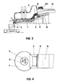
- - la figure 3 montre schématiquement la phase de poussée des ferrailles préchauffées vers la zone de fusion
- -la figure 4 est une vue de dessus très schématique de l'installation de l'invention.
- - Figure 1 is a very schematic side view of the device of the invention, showing the introduction of cold scrap in the oven enclosure
- - Figure 2 schematically shows the supply of a new stock of cold scrap in front of the oven loading door
- - Figure 3 schematically shows the pushing phase of the preheated scrap towards the melting zone
- FIG. 4 is a very schematic top view of the installation of the invention.
En se reportant tout d'abord à l'ensemble des figures 1 et 4, on y voit que le four électrique de l'invention, qui est un four fixe en position et qui comporte une sole classique 1 en matériau réfractaire munie d'une évacuation d'acier liquide vers une poche 3 constituée par une busette à tiroir 2 classique, a son enceinte intérieure réalisée de façon très particulière, car définissant, à côté de la sole 1 et avec le plancher 9, un espace latéral 4 d'assez grand volume destiné à un stockage préalable des ferrailles froides avant leur introduction dans la zone de fusion, c'est-à-dire sur la sole 1, là où agissent les arcs électriques provenant des électrodes 5.Referring first to all of Figures 1 and 4, it can be seen that the electric oven of the invention, which is a stationary oven and which comprises a
L'espace latéral 4 conforme à l'invention a un volume important, par exemple de l'ordre d'un bon tiers de l'ensemble du volume de l'enceinte intérieure du four, de façon à ce que d'une part on puisse y introduire facilement des ferrailles de grandes dimensions et à ce que d'autre part on puisse y stocker un volume important de ferrailles, cet espace latéral 4 étant raccordé à la conduite 16 d'évacuation des fumées du four, de façon à être traversé par lesdites fumées, ce qui permet de profiter au mieux de l'avantage particulier de l'invention qui consiste à récupérer la chaleur des fumées pour réaliser un préchauffage des ferrailles avant qu'elles soient introduites dans la zone de fusion. Préférentiellement, comme c'est le cas dans l'exemple considéré, l'espace latéral 4 de l'invention a une hauteur importante, de l'ordre de deux à trois fois celle de la partie centrale 6 de la voûte 7 du four par exemple, ce qui permet, comme on le verra ci-dessous, une mise en oeuvre particulièrement avantageuse de l'invention, d'une part parce qu'elle permet d'alimenter aisément l'espace 4 en ferrailles froides à l'aide d'une trappe ou porte 8 placée à la partie supérieure dudit espace, et d'autre part parce qu'elle permet de profiter à l'optimum du préchauffage des ferrailles dû aux fumées du fait qu'il est possible de n'alimenter la sole qu'avec les ferrailles situées à la partie inférieure du tas 10 stocké dans l'espace latéral 4, c'est-à-dire les plus chaudes parce que situées le plus près de la zone active de la sole, et parce qu'ayant séjourné plus longtemps dans l'espace latéral 4 que les ferrailles se trouvant à la partie supérieure dudit tas 10.The
Comme on peut le voir sur les figures 1 et 4, l'enceinte intérieure du four a, en raison de la présence de l'espace latéral 4 de l'invention, une forme tourmentée, qu'il serait très difficile de réaliser à l'aide de matériau réfractaire: hormis la sole 1 et la zone 6 réalisées en matériau réfractaire et hormis la plus grande partie du plancher 9 de l'espace latéral 4 réalisé sous forme de construction massive et incliné vers la sole comme représenté sur la figure 1, les parois et la voûte du four sont métalliques et comportent, dans les parties les plus chaudes, des zones refroidies par circulation d'eau, ou autre fluide, cette technique étant maintenant courante dans la constitution des parois de fours électriques.As can be seen in Figures 1 and 4, the internal enclosure of the oven has, due to the presence of the
Par ailleurs, afin qu'il soit possible de pousser régulièrement la partie inférieure du tas de ferrailles 10 stocké dans l'espace latéral 4 vers la zone de fusion, un bloc d'acier 11 servant de poussoir et actionné par un vérin 12 est placé, en sa position reculée comme représenté sur la figure 1, sur la partie du plancher incliné 9 qui est extérieure à l'enceinte du four. Comme on le voit sur le dessin, le bloc pousseur 11a, en position reculée, avantageusement son front avant situé à la limite ou au dehors de l'espace latéral 4, afin de ne pas gêner la formation du tas 10.Furthermore, so that it is possible to regularly push the lower part of the
Sur la figure 1, on a représenté la phase d'introduction, dans l'espace latéral 4 de l'invention, d'une portion 13 de ferrailles froides venant s'ajouter au tas 10 de ferrailles déjà préchauffées que contient ledit espace 4.FIG. 1 shows the phase of introduction, into the
Pour introduire la portion 13, qui se trouvait sur le plancher de travail 14, on a ouvert, par basculement vers le haut, la porte 8, et l'on pousse alors, à l'aide d'un bouteur 15, ladite portion de ferrailles froides à l'intérieur de l'espace latéral 4 où elle tombe sur le dessus du tas 10.To introduce the
Puis, comme on le voit maintenant sur la figure 2, on referme la porte 8 et on amène, à l'aide d'un électroaimant 160, une nouvelle portion 131 de ferrailles froides sur le plancher de travail 14 de l'aciérie.Then, as can now be seen in FIG. 2, the
Ensuite, comme on le voit sur la figure 3, on fait avancer, par sortie de la tige du vérin 12, le poussoir 11 vers l'avant, ce qui a pour effet, comme on le voit clairement sur le dessin, d'introduire, dans le laboratoire délimité par la sole 1, uniquement la partie inférieure du tas de ferrailles 10, partie qui est la plus chaude non seulement parce qu'elle est située le plus près de la zone de rayonnement maximal, mais encore parce qu'elle a séjourné le plus longtemps dans l'espace latéral 4, comme on le voit à l'examen des figures 1 et 2, et a été traversée par les fumées aspirées par la conduite d'évacuation 16.Then, as can be seen in FIG. 3, the
Claims (2)
Priority Applications (1)
| Application Number | Priority Date | Filing Date | Title |
|---|---|---|---|
| AT82400101T ATE20550T1 (en) | 1981-01-20 | 1982-01-20 | CONTINUOUSLY FEED ELECTRIC ARC FURNACE FOR MELTING SCRAP. |
Applications Claiming Priority (2)
| Application Number | Priority Date | Filing Date | Title |
|---|---|---|---|
| FR8100996A FR2498309B1 (en) | 1981-01-20 | 1981-01-20 | ELECTRIC OVEN FOR SCRAP MELTING AND CONTINUOUSLY SUPPLIED |
| FR8100996 | 1981-01-20 |
Publications (2)
| Publication Number | Publication Date |
|---|---|
| EP0056773A1 EP0056773A1 (en) | 1982-07-28 |
| EP0056773B1 true EP0056773B1 (en) | 1986-06-25 |
Family
ID=9254332
Family Applications (1)
| Application Number | Title | Priority Date | Filing Date |
|---|---|---|---|
| EP19820400101 Expired EP0056773B1 (en) | 1981-01-20 | 1982-01-20 | Continuously charged electric-arc furnace for melting scrap |
Country Status (7)
| Country | Link |
|---|---|
| US (1) | US4423514A (en) |
| EP (1) | EP0056773B1 (en) |
| JP (1) | JPS5925139B2 (en) |
| AT (1) | ATE20550T1 (en) |
| CA (1) | CA1173880A (en) |
| DE (1) | DE3271809D1 (en) |
| FR (1) | FR2498309B1 (en) |
Families Citing this family (23)
| Publication number | Priority date | Publication date | Assignee | Title |
|---|---|---|---|---|
| US4445849A (en) * | 1981-05-25 | 1984-05-01 | Swiss Aluminium Ltd. | Device for thermal treatment of scrap |
| FR2539861B1 (en) * | 1983-01-20 | 1987-08-07 | Ferco Int Usine Ferrures | DEVICE FOR AUTOMATICALLY FEEDING THE CRUCIBLE OF A PRESSURE CASTING MACHINE IN A HOT CHAMBER |
| FR2562222B1 (en) * | 1984-03-28 | 1986-08-01 | Litchinko Catherine | INSTALLATION AND METHOD FOR CONTINUOUSLY LOADING A REACTOR IN SOLID MATERIAL AND HEATING THE SAME WITH THE GAS EMITTED BY THE REACTOR |
| DE3421485A1 (en) * | 1984-06-08 | 1985-12-12 | Fuchs Systemtechnik GmbH, 7601 Willstätt | ARC FURNACE WITH A RECEIVING ROOM FOR CHARGED GOODS ON ONE SIDE OF THE FURNACE |
| ATE37947T1 (en) * | 1984-06-08 | 1988-10-15 | Fuchs Systemtechnik Gmbh | ARC FURNACE WITH A LOADING SPACE PROVIDED ON ONE SIDE OF THE FURNACE BODY. |
| US4564388A (en) * | 1984-08-02 | 1986-01-14 | Intersteel Technology, Inc. | Method for continuous steelmaking |
| AU604228B2 (en) * | 1986-02-24 | 1990-12-13 | John Didea | Improved method of disposal and recycling of scrap metal from sea and other vessels |
| DE3906653A1 (en) * | 1989-03-02 | 1990-09-06 | Fuchs Technology Ag | Melt-down unit with shaft-type charging-material preheater |
| AT391757B (en) * | 1989-04-13 | 1990-11-26 | Voest Alpine Ind Anlagen | PLANT FOR METALLURGICAL TREATMENT OF METALS, METAL COMPOUNDS AND / OR METAL ALLOYS |
| US5071047A (en) * | 1990-06-04 | 1991-12-10 | Claire Cordisco | Baby carrier |
| JPH0754797Y2 (en) * | 1990-11-07 | 1995-12-18 | 新日本製鐵株式会社 | Furnace structure of continuous scrap charging type arc furnace |
| US5634960A (en) * | 1995-02-16 | 1997-06-03 | Elkem A/S | Scrap melting in a submerged arc furnace |
| DE19945489A1 (en) * | 1999-09-22 | 2001-04-05 | Sms Demag Ag | Method and device for introducing bulk material into a metallurgical vessel |
| US6473446B2 (en) * | 2000-12-13 | 2002-10-29 | Sms Demag, Inc. | Electric furnace for steel making |
| US6801563B2 (en) * | 2001-11-07 | 2004-10-05 | Sms Demag, Inc. | Apparatus to manipulate scrap in a scrap charger |
| WO2004036131A1 (en) * | 2002-10-15 | 2004-04-29 | Sms Demag Ag | Electric furnace for steel making |
| EP2014742B1 (en) * | 2006-04-28 | 2018-08-08 | JP Steel Plantech Co. | Glowing coke delivering equipment and method of delivering the same |
| US8702367B2 (en) * | 2007-03-21 | 2014-04-22 | Edw. C. Levy Co. | Method, and process for preparing a recyclable material |
| DE102010049238A1 (en) * | 2010-10-25 | 2012-04-26 | Intracon Gmbh | Scrap pusher |
| CN102183150B (en) * | 2011-04-25 | 2013-07-03 | 中冶赛迪工程技术股份有限公司 | Quick feeding device for feeding waste steel into electric furnace and feeding method thereof |
| DE102011087065A1 (en) | 2011-11-24 | 2013-05-29 | Sms Siemag Ag | Electric arc furnace and method of its operation |
| CN203132356U (en) * | 2011-12-27 | 2013-08-14 | 钢铁普蓝特克股份有限公司 | Electric arc furnace |
| CN108085507A (en) * | 2016-11-23 | 2018-05-29 | 攀枝花市九鼎智远知识产权运营有限公司 | A kind of feed system based on electron-beam cold bed furnace |
Family Cites Families (9)
| Publication number | Priority date | Publication date | Assignee | Title |
|---|---|---|---|---|
| DE148129C (en) * | ||||
| US1522665A (en) * | 1922-02-16 | 1925-01-13 | Wright Parvin | Electric furnace and method of operating the same |
| DE1250644B (en) * | 1964-01-14 | 1900-01-01 | ||
| US3441651A (en) * | 1966-02-23 | 1969-04-29 | Canadian Patents Dev | Method and apparatus for heat recovery in electric arc furnaces |
| FR1602675A (en) * | 1968-07-31 | 1971-01-11 | ||
| BE755725A (en) * | 1969-10-23 | 1971-02-15 | Huettenwerk Oberhausen Ag | ARC OVEN EQUIPPED WITH AN IRON SPONGE CHARGING DEVICE |
| US3896257A (en) * | 1970-09-24 | 1975-07-22 | Sadamu Kinoshita | Electric arc furnace for melting metals and metal melting method using such furnace |
| DE2434747A1 (en) * | 1974-07-19 | 1976-01-29 | Krupp Gmbh | Electric open hearth furnace for steel mfr. - with separate addn. of iron ore and large amt. of scrap |
| US4225745A (en) * | 1978-09-05 | 1980-09-30 | Harwell Earnest W | Method for charging small particles of iron or steel directly into molten metal in an arc furnace |
-
1981
- 1981-01-20 FR FR8100996A patent/FR2498309B1/en not_active Expired
- 1981-11-30 US US06/325,951 patent/US4423514A/en not_active Expired - Fee Related
-
1982
- 1982-01-13 JP JP57003993A patent/JPS5925139B2/en not_active Expired
- 1982-01-19 CA CA000394460A patent/CA1173880A/en not_active Expired
- 1982-01-20 DE DE8282400101T patent/DE3271809D1/en not_active Expired
- 1982-01-20 AT AT82400101T patent/ATE20550T1/en not_active IP Right Cessation
- 1982-01-20 EP EP19820400101 patent/EP0056773B1/en not_active Expired
Non-Patent Citations (1)
| Title |
|---|
| H. Lecompte Cours d'Acierie, Editions de la Revue de Metallurgie, p. 167,171 * |
Also Published As
| Publication number | Publication date |
|---|---|
| CA1173880A (en) | 1984-09-04 |
| JPS5925139B2 (en) | 1984-06-14 |
| FR2498309A1 (en) | 1982-07-23 |
| DE3271809D1 (en) | 1986-07-31 |
| US4423514A (en) | 1983-12-27 |
| ATE20550T1 (en) | 1986-07-15 |
| JPS57142477A (en) | 1982-09-03 |
| EP0056773A1 (en) | 1982-07-28 |
| FR2498309B1 (en) | 1986-04-11 |
Similar Documents
| Publication | Publication Date | Title |
|---|---|---|
| EP0056773B1 (en) | Continuously charged electric-arc furnace for melting scrap | |
| EP0462898B1 (en) | Process and installation for smelting of a charge in a furnace | |
| FR2647196A1 (en) | COLD CREUSET DRAINED BY THE BOTTOM | |
| EP0734458B1 (en) | Loading device for feeding liquid metal into an electric furnace | |
| EP0649477A1 (en) | Electric furnace for melting scrap iron | |
| FR2517422A1 (en) | METHOD AND DEVICE FOR RECOVERING COMBUSTIBLE GASES IN AN ELECTROMETALLURGY FURNACE | |
| CA2295393A1 (en) | Distributor of continuous casting of metals, of a type allowing at least one plasma torch for heating metal | |
| EP1457575B1 (en) | Device for observing the charge in an electric steel production furnace | |
| EP0666325B1 (en) | Direct curvent furnace for melting of metal | |
| EP0468832B1 (en) | Furnace for holding the temperature and for metallurgical treatment | |
| CN206160705U (en) | Take sealed electric arc furnace filler device | |
| EP0127504B1 (en) | Metallurgical melting process, and direct current arc furnace therefor | |
| EP0768017B1 (en) | Method and furnace for making a molten product | |
| BE1014844A3 (en) | Submerged arc electric furnace with liquid metal electrodes for the smelting of scrap and minerals for the production of steel | |
| KR101184440B1 (en) | Separating method for metal wastes | |
| BE532283A (en) | ||
| FR2852089A1 (en) | Door stopper for the sealed closure of the slag scouring door of an electric furnace which fits into a housing of the same shape in the upper part of the furnace hearth | |
| BE550259A (en) | ||
| BE423557A (en) | ||
| LU88440A1 (en) | Charging device for feeding molten metal - into an electric melting furnace | |
| CN106403581A (en) | Filling device with sealed electric arc furnace | |
| BE885996A (en) | FUSION OVEN FOR RADIOACTIVE WASTE | |
| FR2811071A1 (en) | Electric immersion heated furnace for heating the interior of a molten non-ferrous metal has tank that pivots intermittently about a horizontal axis between a vertical position of the chamber walls and an inclined position | |
| FR2692971A1 (en) | Furnace for melting and maintaining a metal in a molten state - comprising a hearth for storing the metal charge, and electric heating system to melt and maintain charge in molten state | |
| FR2670504A1 (en) | Plant for melting iron scrap for steel production |
Legal Events
| Date | Code | Title | Description |
|---|---|---|---|
| PUAI | Public reference made under article 153(3) epc to a published international application that has entered the european phase |
Free format text: ORIGINAL CODE: 0009012 |
|
| AK | Designated contracting states |
Designated state(s): AT BE CH DE FR GB IT LU NL SE |
|
| 17P | Request for examination filed |
Effective date: 19820630 |
|
| RAP1 | Party data changed (applicant data changed or rights of an application transferred) |
Owner name: CLECIM SA |
|
| GRAA | (expected) grant |
Free format text: ORIGINAL CODE: 0009210 |
|
| AK | Designated contracting states |
Kind code of ref document: B1 Designated state(s): AT BE CH DE FR GB IT LI LU NL SE |
|
| REF | Corresponds to: |
Ref document number: 20550 Country of ref document: AT Date of ref document: 19860715 Kind code of ref document: T |
|
| ITF | It: translation for a ep patent filed |
Owner name: JACOBACCI & PERANI S.P.A. |
|
| REF | Corresponds to: |
Ref document number: 3271809 Country of ref document: DE Date of ref document: 19860731 |
|
| PLBE | No opposition filed within time limit |
Free format text: ORIGINAL CODE: 0009261 |
|
| STAA | Information on the status of an ep patent application or granted ep patent |
Free format text: STATUS: NO OPPOSITION FILED WITHIN TIME LIMIT |
|
| 26N | No opposition filed | ||
| PGFP | Annual fee paid to national office [announced via postgrant information from national office to epo] |
Ref country code: CH Payment date: 19920127 Year of fee payment: 11 |
|
| ITTA | It: last paid annual fee | ||
| PG25 | Lapsed in a contracting state [announced via postgrant information from national office to epo] |
Ref country code: LI Effective date: 19930131 Ref country code: CH Effective date: 19930131 |
|
| REG | Reference to a national code |
Ref country code: CH Ref legal event code: PL |
|
| PGFP | Annual fee paid to national office [announced via postgrant information from national office to epo] |
Ref country code: FR Payment date: 19931223 Year of fee payment: 13 |
|
| PGFP | Annual fee paid to national office [announced via postgrant information from national office to epo] |
Ref country code: GB Payment date: 19940111 Year of fee payment: 13 |
|
| PGFP | Annual fee paid to national office [announced via postgrant information from national office to epo] |
Ref country code: SE Payment date: 19940118 Year of fee payment: 13 |
|
| PGFP | Annual fee paid to national office [announced via postgrant information from national office to epo] |
Ref country code: AT Payment date: 19940121 Year of fee payment: 13 |
|
| PGFP | Annual fee paid to national office [announced via postgrant information from national office to epo] |
Ref country code: NL Payment date: 19940131 Year of fee payment: 13 Ref country code: LU Payment date: 19940131 Year of fee payment: 13 Ref country code: DE Payment date: 19940131 Year of fee payment: 13 |
|
| PGFP | Annual fee paid to national office [announced via postgrant information from national office to epo] |
Ref country code: BE Payment date: 19940209 Year of fee payment: 13 |
|
| EPTA | Lu: last paid annual fee | ||
| PG25 | Lapsed in a contracting state [announced via postgrant information from national office to epo] |
Ref country code: LU Free format text: LAPSE BECAUSE OF NON-PAYMENT OF DUE FEES Effective date: 19950120 Ref country code: GB Effective date: 19950120 Ref country code: AT Effective date: 19950120 |
|
| PG25 | Lapsed in a contracting state [announced via postgrant information from national office to epo] |
Ref country code: SE Effective date: 19950121 |
|
| EAL | Se: european patent in force in sweden |
Ref document number: 82400101.0 |
|
| PG25 | Lapsed in a contracting state [announced via postgrant information from national office to epo] |
Ref country code: BE Effective date: 19950131 |
|
| BERE | Be: lapsed |
Owner name: CLECIM SA Effective date: 19950131 |
|
| PG25 | Lapsed in a contracting state [announced via postgrant information from national office to epo] |
Ref country code: NL Effective date: 19950801 |
|
| GBPC | Gb: european patent ceased through non-payment of renewal fee |
Effective date: 19950120 |
|
| PG25 | Lapsed in a contracting state [announced via postgrant information from national office to epo] |
Ref country code: FR Effective date: 19950929 |
|
| NLV4 | Nl: lapsed or anulled due to non-payment of the annual fee |
Effective date: 19950801 |
|
| PG25 | Lapsed in a contracting state [announced via postgrant information from national office to epo] |
Ref country code: DE Effective date: 19951003 |
|
| EUG | Se: european patent has lapsed |
Ref document number: 82400101.0 |
|
| REG | Reference to a national code |
Ref country code: FR Ref legal event code: ST |