EP0056549A2 - Elektromechanische Wandleranordnung - Google Patents
Elektromechanische Wandleranordnung Download PDFInfo
- Publication number
- EP0056549A2 EP0056549A2 EP81402050A EP81402050A EP0056549A2 EP 0056549 A2 EP0056549 A2 EP 0056549A2 EP 81402050 A EP81402050 A EP 81402050A EP 81402050 A EP81402050 A EP 81402050A EP 0056549 A2 EP0056549 A2 EP 0056549A2
- Authority
- EP
- European Patent Office
- Prior art keywords
- film
- piezoelectric
- polymer
- electrodes
- structure according
- Prior art date
- Legal status (The legal status is an assumption and is not a legal conclusion. Google has not performed a legal analysis and makes no representation as to the accuracy of the status listed.)
- Granted
Links
Images


Classifications
-
- H—ELECTRICITY
- H04—ELECTRIC COMMUNICATION TECHNIQUE
- H04R—LOUDSPEAKERS, MICROPHONES, GRAMOPHONE PICK-UPS OR LIKE ACOUSTIC ELECTROMECHANICAL TRANSDUCERS; ELECTRIC HEARING AIDS; PUBLIC ADDRESS SYSTEMS
- H04R17/00—Piezoelectric transducers; Electrostrictive transducers
- H04R17/005—Piezoelectric transducers; Electrostrictive transducers using a piezoelectric polymer
Definitions
- the invention relates to transducer devices using polymer films capable of exhibiting piezoelectricity phenomena by application of a polarization field.
- the invention applies in particular to structures composed of piezoelectric polymer films associated with other polymer films, in particular to a structure comprising at least one layer of polar polymer associated with another layer of polymer, such as for equal thickness, the mechanical response to an electrical control voltage is increased compared to that which a homogeneous film of the same polar polymer would produce.
- Certain films of polar polymers such as polyvinyl chloride (PVC), polyvinyl fluoride (PVF), polyvinylidene fluoride (PVF 2 ) and certain polymers such as PVF 2 - PTFE (polyvinylidene fluoride - polyethylene tetrafluoride), are known to have piezoelectric properties, and find their applications in electroacoustic transducers and sensors for example.
- PVF 2 - PTFE polyvinylidene fluoride - polyethylene tetrafluoride
- the piezoelectric properties of these films are described by a tensorial relationship between the components P i of the polarization and the components X jk of the mechanical stresses.
- a tensor called the tensor of the piezoelectric coefficients D ijk .
- a piezoelectric polymer has piezoelectric coefficients that are higher as the value of the remanent polarization is high, and as its mechanical flexibility, in a direction considered, is higher .
- K the electro transducer effect mechanical. More precisely, K 2 is equal to the ratio of the mechanical energy transformed by the piezoelectric effect, to the stored electrical energy.
- the advantage of the invention with respect to the devices existing in the prior art lies in the maximum coupling of electrical energy, at low voltage, in order to derive the maximum of mechanical energy therefrom.
- a monolithic device has a certain stiffness which, during an electrical excitation, counteracts the mechanical deformations and. by this fact therefore limits the piezoelectric effects perceived externally.
- the results can be improved by increasing the value of the electrical energy given to the device.
- this effect can be achieved by reducing the thickness of the piezoelectric film, but in this case, the mechanical resistance of the device is no longer satisfactory.
- a device according to the invention makes it possible to maintain good mechanical strength, since the total thickness of the materials is unchanged, to significantly increase the piezoelectric effects by reducing the influence of the stiffness inherent in the piezoelectric layers used and to deliver more electrical energy to the active layers of the device.
- the present patent application relates to a structure comprising at least one piezoelectric film in which the relative elongation per applied volt, as well as the mechanical energy supplied by applied volt, are greater than those of the homogeneous polar polymer of the same thickness.
- the subject of the invention is an electromechanical transducer structure comprising electrodes between which an electric voltage is applied and at least one piezoelectric polymer film, characterized in that said film cooperates with at least one element having a less rigidity than that of said film; the voltage applied between said electrodes acting exclusively on said film.
- the lifting element is a film endowed with great mechanical flexibility, metallized on its two faces.
- the metalli sations are electrically joined so as not to create any voltage drop between the faces; on these metallizations are deposited layers of piezoelectric polymer subjected to all of the electrical voltage applied to external electrodes.
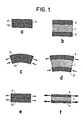
- FIG. 1 represents the behavior, during external electrical stresses, of a transducer device according to the prior art, and of a device according to the invention.
- a device according to the prior art is shown in the left part of the figure, that according to the invention was shown in the right part.
- a device as it exists in the prior art, consists of a monolithic film of piezoelectric material, for example a polymer, as shown in FIG.
- a separation line 14 which limits two layers (10 and 11) in the film.
- a device which will be described more precisely in the following description, comprises a lifting film 1 of flexible non-piezoelectric material, sandwiched between two films of piezoelectric materials 3 and 3 ', as indicated in Figure 1h. Films 3 and 3 'are mechanically integral with film 1.
- the piezoelectric layers work in flexion, as shown in the figure lc by a device of the prior art and in FIG. 1d by a device according to the invention, it can be seen that the overall differences in thickness of the films, as well as the differences in rigidity at the level of the separation of the different layers, allow to obtain a higher motor torque in the device according to the invention assuming that the excitation voltage is exclusively applied to the layers 3 and 3 '.
- FIG. 2 represents an embodiment of a device according to the invention.
- a layer of piezoelectric polymer 3 and 3 ′ is deposited, for example polyvinylidene fluoride PVF 2 .
- Each of these layers is covered by an electrode 4 and 4 ', connected respectively by connections 5 and 5', to an electric generator delivering a voltage V.
- the electric energy delivered by this electric generator is only supplied, through metallizations 2 and 2 ', with active layers 3 and 3'.
- the transformed mechanical energy is greater than in a piezoelectric polymer device of the same thickness, since the capacity of the piezoelectric layers is higher, due to the reduction in thickness.
- a symmetrical structure is adopted which provides the assembly with a stable shape during the effects of thermal expansion.
- FIG. 3 represents an alternative embodiment of a device according to the invention in the sense that the layer 1 and the metallizations 2 and 2 ′ are replaced by a single layer of conductive polymer 6. It is indeed advantageous to replace the material metallized by a conductive polymer of the same flexibility.
- These conductive polymers are generally prepared from an elastomer, in which particles of carbon or of metals are included: copper, silver copper ...
- the remanent polarizations of the piezoelectric layers 3 and 3 ′ are oriented in the same direction to obtain the most intense traction and compression effects; taking into account that the electric control fields have the same direction. However, by reversing one of the polarizations one can obtain an operation in bending.
- FIG. 4 represents a variant of FIG. 2.
- the composite film is identical to that described above and the references are the same.
- Figure 5 is a variant of Figure 2 under the same conditions as Figure 4.
- This conductive polymer therefore acts as an electrode for the piezoelectric layers 3 and 3 '.
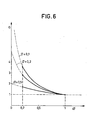
- FIG. 6 represents the evolution of d p s characteristics of a device according to the invention. For flexion operation, it suffices to change the direction of a polarization.
- the gain in relative elongation of a composite film compared to a homogeneous film is represented by the ordinate G of the curve of FIG. 6.
- the magnitude on the abscissa ⁇ represents the ratio of the sum of the thicknesses of the piezoelectric films 3 and 3 ′, to the total thickness of the laminated structure.
- the coefficient ⁇ represents the flexibility ratio of the active piezoelectric material composing the layers 3 to 3 ′, to the flexibility of elastic material, composing the layer 1 or 6.
- FIG. 6 shows the variation of the gain as a function of the ratio of the thicknesses according to certain values of the coefficient ⁇ .
- ⁇ the gain G is minimal whatever the value of the quantity
- the piezoelectric layers are polyvinylidene fluoride PVF 2 deposited on the intermediate polymer by dipping. PVF 2 is dissolved in dymethyl formamide DMF in an amount of 100 to 200 g / 1.
- the intermediate polymer film is coated by passage through a tank of PVF 2 + DMF solution. The solvent is evaporated at the temperature of 70 to 80 ° C by jets of hot air, or radiation of electrical resistances. The low temperature favors the appearance of the non-oriented y phase.
- the film can then be stretched, by a factor of 2 to 3 at 90 - 100 ° C: phase Y is therefore transformed into oriented ⁇ phase; if the composite film is not stretched, its mechanical and piezoelectric properties will be isotropic in its plane.
- the composite film is then metallized on its two faces, using for example the deposition of aluminum under vacuum. It is then polarized between these latter electrodes, by applying an electric field of 0.5 to 1 MV / cm in the PVF 2 layers, at 80 ° C. for a few minutes: the polarization configuration essentially depends on the results that the 'we wish to obtain.
- the voltage generator in FIGS. 2 to 5 is then replaced by a bias voltage generator.
- the thicknesses of the achievable piezoelectric layers are greater than or equal to 1 ⁇ m.
- using a conductive intermediate polymer the same polymers can be used, loaded with particles of carbon or metal.
- the flexible material has been specially described as a polymer having a low stiffness. It is also possible, without departing from the scope of the invention, to use all extensible materials such as foams for example.
- the invention relates to all the applications of piezoelectric films and transducers, in particular electroacoustic such as speakers, headphones, various transmitters.
Landscapes
- Physics & Mathematics (AREA)
- Engineering & Computer Science (AREA)
- Acoustics & Sound (AREA)
- Signal Processing (AREA)
- Piezo-Electric Transducers For Audible Bands (AREA)
Applications Claiming Priority (2)
| Application Number | Priority Date | Filing Date | Title |
|---|---|---|---|
| FR8100780A FR2498406A1 (fr) | 1981-01-16 | 1981-01-16 | Structure de transducteur electromecanique |
| FR8100780 | 1981-01-16 |
Publications (3)
| Publication Number | Publication Date |
|---|---|
| EP0056549A2 true EP0056549A2 (de) | 1982-07-28 |
| EP0056549A3 EP0056549A3 (en) | 1982-08-04 |
| EP0056549B1 EP0056549B1 (de) | 1985-03-27 |
Family
ID=9254236
Family Applications (1)
| Application Number | Title | Priority Date | Filing Date |
|---|---|---|---|
| EP19810402050 Expired EP0056549B1 (de) | 1981-01-16 | 1981-12-22 | Elektromechanische Wandleranordnung |
Country Status (4)
| Country | Link |
|---|---|
| EP (1) | EP0056549B1 (de) |
| JP (1) | JPS57138300A (de) |
| DE (1) | DE3169622D1 (de) |
| FR (1) | FR2498406A1 (de) |
Cited By (3)
| Publication number | Priority date | Publication date | Assignee | Title |
|---|---|---|---|---|
| FR2519503A1 (fr) * | 1981-12-31 | 1983-07-08 | Thomson Csf | Transducteurs piezoelectriques polymeres et procede de fabrication |
| EP0057982B1 (de) * | 1981-02-06 | 1985-12-11 | EMI Limited | Sensor für Druckwellen |
| EP0420190A3 (en) * | 1989-09-26 | 1992-04-22 | Atochem North America, Inc. | Ultrasonic contact transducer and array |
Family Cites Families (4)
| Publication number | Priority date | Publication date | Assignee | Title |
|---|---|---|---|---|
| US3816774A (en) * | 1972-01-28 | 1974-06-11 | Victor Company Of Japan | Curved piezoelectric elements |
| GB1515287A (en) * | 1974-05-30 | 1978-06-21 | Plessey Co Ltd | Piezoelectric transducers |
| GB1593271A (en) * | 1976-09-21 | 1981-07-15 | Standard Telephones Cables Ltd | Electro-acoustic transducers |
| DE2803168C3 (de) * | 1978-01-25 | 1982-10-21 | Friedemann Dipl.-Ing. Dr. 8069 Jetzendorf Meggl | Elektromechanischer Wandler |
-
1981
- 1981-01-16 FR FR8100780A patent/FR2498406A1/fr not_active Withdrawn
- 1981-12-22 EP EP19810402050 patent/EP0056549B1/de not_active Expired
- 1981-12-22 DE DE8181402050T patent/DE3169622D1/de not_active Expired
-
1982
- 1982-01-14 JP JP475282A patent/JPS57138300A/ja active Pending
Cited By (4)
| Publication number | Priority date | Publication date | Assignee | Title |
|---|---|---|---|---|
| EP0057982B1 (de) * | 1981-02-06 | 1985-12-11 | EMI Limited | Sensor für Druckwellen |
| FR2519503A1 (fr) * | 1981-12-31 | 1983-07-08 | Thomson Csf | Transducteurs piezoelectriques polymeres et procede de fabrication |
| EP0086922A1 (de) * | 1981-12-31 | 1983-08-31 | Thomson-Csf | Verfahren zur Herstellung von piezo-elektrischen Wandlern aus Polymeren |
| EP0420190A3 (en) * | 1989-09-26 | 1992-04-22 | Atochem North America, Inc. | Ultrasonic contact transducer and array |
Also Published As
| Publication number | Publication date |
|---|---|
| EP0056549A3 (en) | 1982-08-04 |
| EP0056549B1 (de) | 1985-03-27 |
| FR2498406A1 (fr) | 1982-07-23 |
| DE3169622D1 (en) | 1985-05-02 |
| JPS57138300A (en) | 1982-08-26 |
Similar Documents
| Publication | Publication Date | Title |
|---|---|---|
| EP0168313B1 (de) | Piezoelektrischer Wandler und Druckfühler mit einem solchen Wandler | |
| EP0086922B1 (de) | Verfahren zur Herstellung von piezo-elektrischen Wandlern aus Polymeren | |
| FR2645349A1 (fr) | Structure piezoelectrique stratifiee et procede pour sa formation | |
| FR2496380A1 (fr) | Dispositif piezoresistif a commande electrique | |
| JP3093849B2 (ja) | 可撓性積層圧電素子 | |
| CA1124373A (en) | Pyroelectric infrared detector | |
| EP3443602B1 (de) | Ein stromgenerator mit einem magnetoelektrischen wandler | |
| EP2673873A1 (de) | Optimierte vorrichtung zur umwandlung von mechanischer energie in elektrische energie | |
| FR3082997A1 (fr) | Procede de transfert de couche(s) de materiau depuis un premier substrat sur un deuxieme substrat | |
| FR3029815A1 (fr) | Hydrophone piezoelectrique a perforations et antenne comprenant une pluralite d'hydrophones | |
| CH656010A5 (fr) | Dispositif miniature sensible au champ magnetique et appareil de mesure du champ magnetique comportant un tel dispositif. | |
| FR2730853A1 (fr) | Procede pour polariser une feuille de materiau ferroelectrique de grande surface | |
| FR2556165A1 (fr) | Reseau d'hydrophones en polymere a couches multiples | |
| EP0056549B1 (de) | Elektromechanische Wandleranordnung | |
| FR3012702A1 (fr) | Convertisseur d'une variation d'energie a recuperer en une difference de potentiels | |
| EP0375570B1 (de) | Vorrichtung zur Schwingungensabsorption mit einem piezoelektrischen Element | |
| EP3598512A1 (de) | Pyroelektrische detektionsvorrichtung mit vorgespannt aufgehängter membran | |
| EP2251919B1 (de) | Organischer feldeffekttransistor | |
| FR2701188A1 (fr) | Procédé de fabrication de composant piézoélectrique. | |
| FR2836552A1 (fr) | Capteur d'acceleration | |
| FR3087007A1 (fr) | Dispositif de detection pyroelectrique a membrane rigide | |
| FR3083004A1 (fr) | Dispositif transducteur piezoelectrique et procede de realisation d'un tel dispositif | |
| FR2965991A1 (fr) | Dispositif acoustique d'isolation galvanique | |
| FR2511571A1 (fr) | Transducteur electroacoustique a condensateur a dielectrique solide polarise | |
| EP2198312B1 (de) | Elektrostatische vorrichtung zur dämpfung einer mechanischen vibrationsbewegung eines beweglichen resonanzkörpers |
Legal Events
| Date | Code | Title | Description |
|---|---|---|---|
| PUAI | Public reference made under article 153(3) epc to a published international application that has entered the european phase |
Free format text: ORIGINAL CODE: 0009012 |
|
| PUAL | Search report despatched |
Free format text: ORIGINAL CODE: 0009013 |
|
| AK | Designated contracting states |
Designated state(s): DE GB NL SE |
|
| AK | Designated contracting states |
Designated state(s): DE GB NL SE |
|
| 17P | Request for examination filed |
Effective date: 19820823 |
|
| GRAA | (expected) grant |
Free format text: ORIGINAL CODE: 0009210 |
|
| AK | Designated contracting states |
Designated state(s): DE GB NL SE |
|
| REF | Corresponds to: |
Ref document number: 3169622 Country of ref document: DE Date of ref document: 19850502 |
|
| PG25 | Lapsed in a contracting state [announced via postgrant information from national office to epo] |
Ref country code: SE Effective date: 19851223 |
|
| PLBE | No opposition filed within time limit |
Free format text: ORIGINAL CODE: 0009261 |
|
| STAA | Information on the status of an ep patent application or granted ep patent |
Free format text: STATUS: NO OPPOSITION FILED WITHIN TIME LIMIT |
|
| 26N | No opposition filed | ||
| PG25 | Lapsed in a contracting state [announced via postgrant information from national office to epo] |
Ref country code: NL Effective date: 19860701 |
|
| GBPC | Gb: european patent ceased through non-payment of renewal fee | ||
| NLV4 | Nl: lapsed or anulled due to non-payment of the annual fee | ||
| PG25 | Lapsed in a contracting state [announced via postgrant information from national office to epo] |
Ref country code: DE Effective date: 19860902 |
|
| PG25 | Lapsed in a contracting state [announced via postgrant information from national office to epo] |
Ref country code: GB Effective date: 19881121 |
|
| EUG | Se: european patent has lapsed |
Ref document number: 81402050.9 Effective date: 19860902 |