EP0056335B1 - Cooker provided with an electronic digital timer - Google Patents
Cooker provided with an electronic digital timer Download PDFInfo
- Publication number
- EP0056335B1 EP0056335B1 EP82300185A EP82300185A EP0056335B1 EP 0056335 B1 EP0056335 B1 EP 0056335B1 EP 82300185 A EP82300185 A EP 82300185A EP 82300185 A EP82300185 A EP 82300185A EP 0056335 B1 EP0056335 B1 EP 0056335B1
- Authority
- EP
- European Patent Office
- Prior art keywords
- time
- display
- circuit
- output voltage
- electronic digital
- Prior art date
- Legal status (The legal status is an assumption and is not a legal conclusion. Google has not performed a legal analysis and makes no representation as to the accuracy of the status listed.)
- Expired
Links
- 230000004044 response Effects 0.000 claims description 8
- 230000000977 initiatory effect Effects 0.000 claims description 4
- 238000010411 cooking Methods 0.000 description 69
- 230000008859 change Effects 0.000 description 7
- 238000010586 diagram Methods 0.000 description 7
- 210000001072 colon Anatomy 0.000 description 5
- 230000006870 function Effects 0.000 description 4
- 238000003825 pressing Methods 0.000 description 4
- 230000008901 benefit Effects 0.000 description 3
- 239000011159 matrix material Substances 0.000 description 3
- 238000000034 method Methods 0.000 description 3
- 230000001052 transient effect Effects 0.000 description 3
- 239000003990 capacitor Substances 0.000 description 2
- 238000001816 cooling Methods 0.000 description 2
- 238000001514 detection method Methods 0.000 description 2
- 230000003247 decreasing effect Effects 0.000 description 1
- 230000000694 effects Effects 0.000 description 1
- 238000010438 heat treatment Methods 0.000 description 1
- 239000004973 liquid crystal related substance Substances 0.000 description 1
- 239000000463 material Substances 0.000 description 1
- 238000012986 modification Methods 0.000 description 1
- 230000004048 modification Effects 0.000 description 1
- 238000007493 shaping process Methods 0.000 description 1
Images

Classifications
-
- G—PHYSICS
- G04—HOROLOGY
- G04G—ELECTRONIC TIME-PIECES
- G04G15/00—Time-pieces comprising means to be operated at preselected times or after preselected time intervals
- G04G15/006—Time-pieces comprising means to be operated at preselected times or after preselected time intervals for operating at a number of different times
-
- G—PHYSICS
- G04—HOROLOGY
- G04F—TIME-INTERVAL MEASURING
- G04F3/00—Apparatus which can be set and started to measure-off predetermined or adjustably-fixed time intervals with driving mechanisms, e.g. dosimeters with clockwork
Definitions
- This invention relates to an electronic digital timer and more particularly to an improved electronic digital timer capable of setting time in an analog fashion by operating time setting means and thereby controlling an operation of electric or electronic apparatus.
- a typical control panel for a microwave oven having a conventional electronic digital timer includes a display section which may comprise a plurality of seven-segment type light emitting diode display devices and a digit key pad which includes ten numeral keys for the decimal numerals 0-9 for changing the numeric display on the display section and being operated by setting, for example, time intervals for cooking.
- the panel may also include a cooking mode selection section having various cooking mode keys such as a "HIGH POWER” key for obtaining a high power microwave output from a magnetron and a "COOK" key for starting of the cooking operation.
- a present time display appears on the display section to inform the user of the present time. That is, at this time, the electronic digital timer including the display section and the digit key section operates as an ordinary digital clock. If the user desires to cook by the high power output from the magnetron for 12 minutes and 34 seconds, for example, the "HIGH POWER" key on the cooking mode selection section is first selected and actuated.
- the present time display disappears and a "0000" and "HIGH” displays appear on the display section.
- the "1" digit key is selected and actuated after the appearance of "0000" display.
- the display section provides a display "0001”.
- the display pattern on the display section varies and "1234" display appears on the display section.
- Setting of the cooking time interval "1234" (12 minutes and 34 seconds) is completed. Under this condition, actuation of the "COOK" key starts the cooking which lasts for 12 minutes and 34 seconds.
- Setting cooking time by the use of a plurality of digit keys has many disadvantages, among which are: (1) persons who have long experience with analog type timers (for example, mechanical rotary-type timers) often find it difficult to operate digit keys and often take a longer period of time to familiarize themselves with the digital timer having a plurality of digit keys; (2) when, for example, the user sets the wrong cooking time, they must set the correct cooking time again after putting the display on the display section back in its initial display condition "0000"; and (3) a large space is necessary to provide ten digit keys on the digit key pad of the panel.
- analog type timers for example, mechanical rotary-type timers
- U.K. Patent Application GB-A-2019041 discloses a programmable timer for individual control of a plurality of control functions which comprises a switch for each of the functions, each switch being settable by respective setting elements to be actuated at predetermined on and off time.
- the setting elements comprise sliders of linear potentiometers, which indicate the time settings in an analogue form.
- the output voltages from the linear potentiometers are fed to respective A-D convertors, and the corresponding switch is actuated when a digital display comparator detects coincidence between the value in the convertor and the time of day as shown by a display.
- a problem with this type of switching arrangement is that because the settings on the linear potentiometers can be varied in a continuous manner they may become set at transient positions between adjacent corresponding digital levels, or external noise may effect the circuitry and cause the digital output from the A-D convertor to fluctuate.
- An advantage of the present invention is that a "hysteresis" characteristic is provided in order to prevent fluctuation between adjacent digital levels.
- the present invention provides a cooker provided with an electronic digital timer for displaying time information on an electronic digital display device for the cooker, said electronic digital timer comprising:
- the digital display is preferably varied by operating a single control knob.
- the time setting circuit includes a variable resistor having a movable arm, the position of the movable arm being controlled by the operation of the time setting means and the output voltage being determined by the selecting position of said movable arm.
- the converting means includes a digital-to-analog converter for converting a reference input digital signal into a corresponding reference output voltage, the comparator being arranged to compare the output voltage of the time setting circuit with the reference output voltage und to produce a comparator output signal indicative of the results of such comparison and the processing circuit being arranged to provide the reference input digital signal and being coupled to receive the comparator output signal for changing the reference digital signal in response to the comparator output signal and storing the comparator output signal as the digital corresponding to the comparator output voltage.
- the display control means includes a circuit for receiving the digital signal from the converting means after completion of the converting operation of the converting means and for changing the form of the digital signal to a signal capable of driving the electronic digital display device.
- a second particular embodiment of the invention further includes time setting adjustment means for selection of a present time display mode and a time adjustment mode, the time adjustment mode being divided into an hours setting mode and a minutes setting mode, and the time setting circuit introduces time information in hours in the hours setting mode and introduces time information in minutes in the minutes setting mode.
- Control panel 10 includes a display section 12 and a digit key section 14 which includes ten numerical keys for the decimal numerals 0-9. These digit keys are used for changing the numeric display on the display section 12 and are operated for setting, for example, time intervals for cooking.
- the panel 10 also includes a cooking mode selection section 16 which includes various cooking mode keys, such as a "HIGH POWER" key for obtaining a high power microwave output from a magnetron and a "COOK" key for starting the cooking operation.
- a present time display (for example, 10 o'clock) appears on the display section 12 as shown in Figure 2(a) to inform the user of the present time. That is, at this time, the electronic digital timer including the display section 12 and the digit key section 14 is operated as an ordinary digital clock.
- the "HIGH POWER" key on the cooking mode selection section 16 is first pressed. By this operation, the present time display disappears and "0000" and "HIGH” displays appear on the display section 12 as shown in Figure 2(b).
- the "1" digit key is pressed after the appearance of "0000" display.
- the display section 12 provides a display "0001" as shown in Figure 2(c).
- the display on the display section 12 varies, as shown in Figures 2(d)-2(f) and "1234" display appears on the display section 12 and setting of the cooking time interval "1234" (12 minutes and 34 seconds) is completed.
- pressing of the "COOK” key on the cooking mode selection section 16 starts the cooking which will automatically terminate at 12 minutes and 34 seconds.
- FIG. 3 there is illustrated a microwave oven, generally designated by the numeral 20, including an electronic digital timer constructed in accordance with and embodying the features of the present invention.
- the oven is conventional and includes a front-opening access door 22 to open and close an oven cooking cavity (not shown), which door is shown in Figure 3 in its fully closed position.
- the oven 20 has a control panel 24 provided on the front right side of the oven for providing control of the microwave oven cooking functions.
- the control panel 24 has a display section 26, a time setting knob 28, a cooking mode selection section 30 and a time adjusting button 32.
- the display section 26, the time setting knob 28 and the time adjusting button 32 are included in the electronic digital timer.
- the display section 26 may comprise an electronic character display device such as light emitting diodes, a fluorescent display tube, a liquid crystal display device or the like.
- the electronic character display device includes a plurality of seven-segment type numeral display elements 26a-26d for time display, a colon display element 26e between the hour display elements 26a, 26b, and minute display elements 26c, 26d displayed during the present time display mode and a plurality of cooking mode display elements 25f-26i such as "HIGH", "OVEN”.
- a time setting knob 28 is mounted rotatably on the control panel 24 for changing the time display pattern on the digital time display section 26 by rotating knob 28.
- Index mark 28a on the top surface of the knob 28 points to a rotating position of the knob 28.
- the cooking mode selection section 30 comprises a plurality of cooking mode selection keys 30a-30f, such as a "LOW POWER" key 30b, for obtaining a low power microwave output from a magnetron, a
- GRILL GRILL
- COOK a "COOK" key 30e for starting the cooking operation.
- These keys activate switches, as described below, which switches are rendered conductive or cut-off upon pressing said cooking mode selection keys.
- the time adjusting button 32 is used to adjust the present time display on the display section 26.
- Figure 4 shows one way to operate the digital timer of Figure 3, in particular, to set a cooking time interval.
- the present time display for example, "10:00" 10 o'clock
- the digital time display section 26 appears on the digital time display section 26, as shown in Figure 4(a), to inform the user of the present time.
- numeral display elements 26a-26d and colon display element 26e are operated.
- the "LOW POWER" key 30b on the cooking mode selection section 30 is first pressed. By this operation, the present time display disappears and the numbers "0000" and the work "LOW” appear on the time display section 26, as indicated in Figure 4(b).
- numeral display elements 26a-26d and "LOW" cooking mode display element 26g are operated.
- the time setting knob 28 is turned clockwise and time from “0000" until "1240" (12 minutes and 40 seconds) displayed, as shown in Figure 4(c).
- the time setting knob 28 is turned counter-clockwise from the position of Figure 4(c) and until the time "1234" is displayed, as shown in Figure 4(d).
- the cooking time interval of 12 minutes 34 seconds is set and displayed corresponding to the angular position of the time setting knob 28.
- pressing of the "COOK" key 30e starts the cooking which will automatically terminate at 12 minutes and 34 seconds.
- Figure 5 shows the schematic block diagram of circuitry for the above-mentioned operational sequence. This circuitry may be divided roughly into two portions. A first portion 34A is used for converting an analog signal corresponding to the setting position of the time setting knob 28 into a digital signal to be displayed on the display section 26. A second portion 34B is used for controlling a cooking operation of the microwave oven 20.
- a time setting circuit 36 produces an analog output voltage E corresponding to the angular position of the time setting knob 28.
- a digital-to-analog (D/A) converter 38 produces an analog reference voltage V corresponding to a digital reference input signal Sd thereof, which is changed periodically by a microcomputer 40.
- a comparator 42 compares the output voltage E with the reference voltage V and produces a comparator output signal S which is "H” (binary “1") when output voltage E is higher than reference voltage V and which is "L” (binary "0") when output voltage E is lower than reference voltage V.
- the comparator output signal S is transferred to a central processing unit (CPU) 44 of the microcomputer 40 through an input port 46 and stored in a memory circuit (not shown) of CPU 44.
- CPU 44 changes the reference input digital signal Sd through an output port 48.
- the reference voltage V is changed and the output voltage E is compared with the second reference voltage V in the comparator 42.
- the second comparator output signal S is transferred to CPU 44 and stored in the memory circuit.
- CPU 44 changes the digital reference input signal Sd again for changing the reference voltage V.
- the output voltage E is compared with the third reference voltage V and the comparison result is stored in the memory circuit of CPU 44.
- CPU 44 changes the reference input digital signal Sd on the basis of three stored digital signals, and then a fourth comparison operation is executed. Similar operations are repeated several times, the number of times being determined by the number of converting bits of D/A converter 38. After the completion of the comparison operations, the stored digital signals of the memory circuit of CPU 44 are transferred to the display section 26 through a display output circuit 50 to be displayed as time information corresponding to the position of the time setting knob 28.
- the time setting circuit 36 When the user rotates the time setting knob 28 and fixes it position, the time setting circuit 36 produces an analog output voltage E corresponding to the angular position of the time -setting knob 28.
- the time setting circuit 36 may be constructed by use of a variable resistor.
- the output voltage E of the time setting circuit 36 is applied to a first input terminal 42a of a comparator 42, which may be a differential amplifier, an operation amplifier or other well known comparator circuit.
- the second input terminal 42b of the comparator 42 is supplied with an analog reference voltage V from a digital-to-analog (D/A) converter 38.
- D/A digital-to-analog
- the D/A converter 38 converts a reference input digital signal consisting of a plurality of bits (for example, 6 bits) from a microcomputer 40 into the analog reference voltage V.
- the microcomputer 40 is programmed to sequentially change the reference signal six times during the comparison operation to obtain the binary equivalent of the analog output signal E.
- the first reference signal for all comparisons is preselected; the second to sixth reference signals are automatically changed on the basis of the result of the comparison of the comparator 42.
- the comparator 42 compares the output voltage E from the time setting circuit 36 with the analog reference voltage V from D/A converter 38 and produces the comparator output digital signal S.
- the comparator output signal S of comparator 42 when the output voltage E from the time setting circuit 36 is higher than the analog reference voltage V from D/A converter 38, the comparator output signal S of comparator 42 will be "H", and when the output voltage E from the time setting circuit 36 is lower than the analog reference voltage V from D/A converter 38, the comparator output signal S of the comparator 42 will be "L”.
- the comparator output signal S is applied to the input port 46 of the microcomputer 40.
- the output digital signal of the input port 46 is applied to CPU 44 and stored in the memory circuit of CPU 44. At the same time, CPU 44 produces an output digital signal on the basis of the stored signal thereof.
- the output digital signal of CPU 44 is applied to the input terminals of D/A converter 38 as the reference input digital signal Sd through the output port 48 of the microcomputer 40.
- the analog reference voltage V of D/A converter 38 is changed corresponding to the reference input digital signal Sd.
- the output voltage E of the time setting circuit 36 is compared with the second reference voltage V in the comparator 42.
- the second comparator output signal S is also stored in the memory circuit of CPU 44 and CPU 44 changes the reference input digital signal Sd again on the basis of the two stored signals in the memory circuit for changing the reference voltage V.
- the output voltage E is compared with the third reference voltage V and the third comparator output signal S causes CPU 44 to change the reference input digital signal Sd of D/A converter 38. Similar operations are repeated, six times in all, after which the output voltage E of the time setting circuit 36 is converted into a digital signal consisting of six bits which are stored in the memory circuit of CPU 44.
- the circuitry including D/A converter 38, the comparator 42, CPU 44, the input port 46 and the output port 48 is an analog-to-digital converter for converting the analog output voltage E from the time setting circuit 36 into the digital signal to be displayed on the display section 26 corresponding to said analog output voltage E.
- CPU 44 is controlled by a 50 Hz/60 Hz clock pulse 52 produced by a wave form shaping circuit 54, which circuit 54 converts an AC commercial power signal 56 having the frequency of 50 Hz/60 Hz from an AC power source 58 into a rectangular pulse wave.
- the clock pulse 52 is used as a timing signal in the above-mentioned analog-to-digital converting operation and as a second signal (in case of 60 Hz pulse) for time display. This converting operation will be more detailed later.
- the digital signal stored in the memory circuit of CPU 44 is applied to the display section 26 through the display output circuit 50 of the microcomputer 40, which circuit 50 may be a binary-to-decimal converting circuit.
- the time display pattern on the display section 26 is changed automatically by the clock pulse 52. For example, when the time display is the cooking time, it is counted down to zero, and when the time display is the present time, it is counted up in the usual way.
- the circuitry of Figure 5 includes the second portion 34B for controlling the cooking operation which will now be described.
- the CPU 44 also receives an order signal from the cooking mode selection section 30 and produces an output signal to display a cooking mode on the display section 26. Furthermore, a CPU 44 produces a control signal to a control drive circuit 60 to start the cooking operation when the "COOK" key 30e on the cooking mode selection section 30 is actuated.
- the drive circuit 60 controls a power supply circuit 62 to apply a power supply voltage to a magnetron circuit 64 during the time interval set by the time setting knob 28. The time display of the set time interval is counted down after starting the cooking and the cooking operation is terminated when the cooking time display is returned to initial position "0000".
- a buzzer circuit 66 is operated by an order signal of CPU 44 to inform the user of termination of cooking.
- CPU 44 also produces a control signal to control the drive circuit 60 to change the microwave output power of the magnetron, depending upon whether the "HIGH POWER" key 30a or "LOW POWER” key 30b is operated.
- Figure 6 shows the schematic circuit diagram of circuitry for some of the blocks of Figure 5.
- the time setting circuit 36 comprises a variable resistor 36a, a fixed resistor 36b, connected in parallel with variable resistor 36a, and a fixed resistor 36c having one end connected to one junction of resistors 36a and 36b and the other end connected to a source of voltage +15V.
- the other junction of resistors 36a and 36b is connected to earth potential.
- a movable arm 36d of variable resistor 36a which provides the output voltage of the time setting circuit 36 is connected to the positive input terminal 42a of comparator 42.
- the output voltage of the time setting circuit 36 is obtainable within the range of OV (when the movable arm of the variable resistor 36a is connected to left side end thereof) and (when the movable arm of the variable resistor 36a is connected to right side end thereof).
- the D/A converter 38 ( Figures 6 and 7) comprises a buffer circuit 38a, an input bias circuit 38b consisting of six resistors, each having one end connected to earth potential, and the other end connected to six input terminals D o ⁇ Dg of the buffer circuit 38a respectively, and an output ladder network circuit 38c.
- the output ladder network circuit 38c consists of six resistors R o -R s , each having one end connected to six output terminals A o ⁇ A 5 of the buffer circuit 38a respectively, five resistors R67-Rlo connected between the other ends of adjacent resistors R s- R o respectively, one resistor R 11 connected between the junction of resistors R o , R 10 and earth potential and an output resistor R 12 connected between the junction of resistors R o , R 6 and earth potential.
- the operation of the D/A converter 38 will be explained in detail below.
- the display section 26 comprises an electronic character display device 26x (for example, a fluorescent display tube) having four numeral display elements 26a-26d (fluorescent anode electrodes), the colon display element 26e (fluorescent anode electrode) and four cooking mode display elements 26f-26i fluoresecent anode electrodes), a circuit 26y for driving the cathodes of said fluorescent display tube 26x respectively having five resistors and a circuit 26z for driving the anodes of said fluorescent display tube 26x respectively.
- the fluorescent display tube 26x is a well known device used, for example, with electronic digital tape counters or electronic recording/reproducing level meters of tape decks, and display portions of disc type electronic calculators.
- the fundamental display operation thereof is also well known and operates by having electrons emitted from the heated cathode move to the anode.
- the cathode drive circuit 26y includes five resistors for heating the cathodes of the fluorescent tube 26x. One end of the resistors is connected to a power voltage -15V and the other end of the resistors is connected to the output terminals of the display output circuit 50 of the microcomputer 40.
- the anode drive circuit 26z is used for applying appropriate voltage to the anodes of the fluorescent tube 26x. It includes seven resistors, one end of each being connected to a power voltage -15V and the other end of each being connected to the output terminals of the display output circuit 50 of the microcomputer 40.
- the cooking mode selection section 30 comprises key switches 30a'-30f', corresponding to the cooking mode selection keys 30a-30f of Figure 3, and diodes 30g-30i. These components form a 2x3 matrix circuit.
- the output terminals of the matrix circuit are connected to CPU 44 in microcomputer 40 and through resistors to earth potential.
- the input terminals of the matrix circuit are connected to the cathode drive circuit 26y.
- the drive circuit 60 comprises at least two switching circuits 60a, 60b.
- Each switching circuit includes a switching transistor (Tr1, Tr2) and a relay solenoid (RL,, RL 2 , and is connected between a power voltage +24V and earth potential.
- the first switching circuit 60a controls the power supply circuit 62 in response to the output signal of CPU 44 to supply a power voltage to the magnetron circuit 64 during the period of time when the output signal of CPU 44 appears.
- the second switching circuit 60b controls the output microwave power of the magnetron circuit 64 ("HIGH” or "LOW") in response to an output signal of CPU 44 produced in response to the operations of power select switch 30a or 30b on the cooking mode selection section 30 of control panel 24.
- the power supply circuit 62 includes a fuse 62a, power switches 62b, 62b', a relay switch 62c operated by the relay solenoid RL,, a power transformer 62d and a cooling fan motor 62e for cooling the magnetron of the magnetron circuit.
- the magnetron circuit 64 includes the magnetron 64a, a diode 64b, capacitors 64c, 64d and a relay switch 64e operated by the relay solenoid RL 2 . When the relay switch 64e is closed, the oscillating frequency of the magnetron 64a is reduced by parallel connection of two capacitors 64c, 64d and "LOW" microwave power is supplied from the magnetron 64a.
- the buzzer circuit 66 includes a buzzer 66a, a transistor 66b, a diode 66c and three resistors.
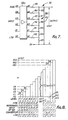
- FIG. 7 shows an example of D/A converter 38 of a 6-bit configuration.
- the buffer circuit 38a of the converter 38 is adapted such that it may deliver a given voltage Vc from each output terminal A o ⁇ A 5 when a "1" digital signal is received at the corresponding input terminal D 0 ⁇ D 5 from the microcomputer 40 and deliver OV when an "0" digital signal is received at the corresponding input terminal Do-D 5 .
- the output voltage Vout of the output ladder circuit 38c therefore, bears a stepwise waveform corresponding to reference input digital signals as shown in Figure 8.
- D/A converter 38 when D/A converter 38 receives a binary digital signal "000000” (decimal “0") on input terminals D 5 Do respectively from the microcomputer 40, the converter 38 produces 0 V (O level) at its output terminal.
- the converter 16 receives "000001” (decimal “1") on input terminals D 5 ⁇ D 0 respectively, it produces a voltage Vout equal to V, (1 level, Figure 8).
- the output voltage from D/A converter 38 varies stepwise from V, to V 63 and the converter 38 produces 64 different levels of the output voltage Vout corresponding to 64 different reference input digital signals Sd. These 64 output voltages are used as the reference voltage V ( Figure 5) to be compared with the output voltage E of the time setting circuit 36.
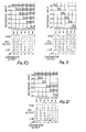
- Figure 9 shows the flow diagram for explaining the operation for converting the output voltage of the time setting circuit 36 into the digital signal to set the display output for the display section 26.
- Figures 10, 11 and 12 illustrate the operations for converting the analog output voltage E of the time setting circuit 36 corresponding to, for example, 63, 0, and 39 level from D/A converter 38 respectively into digital signals.
- cross-hatched portion of the reference input shown a "1" signal and blank portions show a "0" signal.
- the principal converting sequences are as follows: (1) the analog output voltage E is first compared with the predetermined reference voltage V 32 corresponding to the first preselected reference input digital signal "100000”; (2) if the first comparator output signal is "H”, the reference voltage is changed to V 48 corresponding to the reference input digital signal "110000", a first bit of which is stored “H” signals; (3) if the comparator output signal is "L”, the reference voltage is changed to V, 6 corresponding to the reference input digital signal "010000", a first bit of which is the stored "L” signal' (4) the analog output voltage E is compared with said second reference voltage, either V 48 or V '6 ; (5) if the second comparator output signal is "H”, the reference voltage is changed to V 56 (when the first reference voltage is V 48 ) corresponding to the reference input digital signal "111000” and the first and second bits of which are stored “HH” signals; (6) if the second comparator output signal is "H”, the reference voltage is changed to V 24 (when the first reference voltage is V
- the output voltage E of the time setting circuit 36 is higher than or equal to the reference voltage V 63 from D/A converter 38.
- first step 68 of Figure 9 for setting of reference voltage the output signal of the output port 48 (the reference input digital signal Sd of D/A converter 38) is set automatically as "100000" having "1" at the most significant bit (MSB) position and "0" at the other bit positions.
- the reference voltage V 32 of level 32 is produced from D/A converter 38 as a first reference voltage.
- Second step 70 of Figure 9 is a standby step to accommodate response time of the circuit.
- step 72 of Figure 9 for comparison of E and V the output voltage E of the time setting circuit 36 corresponding to substantially 63 level is compared with said first reference voltage V 32 by the comparator 42 and the comparator 42 produces "H” comparator output signal.
- step 74 of Figure 9 for transferring the comparison result said "H" comparator output signal is transferred to the input port 46.
- step 76 of Figure 9 for storing the comparison result the comparator output signal "H” is stored in the memory circuit of CPU 44 at first store position (MSB position) thereof as "1".
- sixth step 78 of Figure 9 for sensing the completion of all comparison operations (six times) CPU 44 checks whether six times comparison operations are completed or not. In this case, CPU 44 decides to return the operation to first step 68 because the checking result is negative. The operation illustrated so far is conducted during time T, as shown in Figure 10.
- step 68 of second time interval Similar operation is conducted during time T 2 after T,.
- the reference input digital signal of D/A converter 38 is set as "110000", in which MSB "1" remains without change because comparison result was "H” ("1"), second bit is set newly as “1” and the rest remain as “0”.
- the voltage of level 48 (V 48 ) is produced from D/A converter 38 as a second reference voltage.
- substantially 63 level output voltage E of the time setting circuit 36 is compared with the second reference voltage of level 48 (V 48 ).
- the reference input digital signal of D/A converter 38 is set as "111000", in which upper two bits remains as “1”, and the third bit is set newly as “1” and the rest remain as “0".
- the voltage of level 56 (V 56 ) is produced from the converter 38 as a third reference signal.
- the substantially 63 level output voltage E of the time setting circuit 36 is compared with the third reference voltage of level 56 (V 56 ) and "H" level comparator output signal is produced, as above.
- the third "H” level comparator output signal is stored in the memory circuit at third store position (third significant bit position) as "1" and operation is returned to the step 68 again.
- data "111111” stored in the memory circuit of CPU 44 is read out in the step 80 for reading out the stored signal and time (for example, cooking time interval) corresponding to the output voltage E of level 63 (“111111") is displayed on the display section 26 in the step 82 for displaying the time information.
- the next example is the detection of 39 level as shown in Figure 12.
- the output voltage of the time setting circuit 36 is within the range of level 39 and level 40 from D/A converter 38.
- the output signal of the output port 48 (the reference input digital signal of D/A converter 38) us automatically set as "100000", as above.
- the reference voltage of level 32 (V 32 ) from the converter 38 is compared with the output voltage E of the time setting circuit 36 corresponding to substantially level 39 by the comparator 42 and the comparator 42 produces "H" comparator output signal.
- Steps 7478 are the same as mentioned above.
- the reference voltage of level 48 (V 48 ) is produced and the comparison operation is conducted by the comparator 42.
- the output voltage E of the time setting circuit 36 (about level 39) is lower than said reference voltage of level 48. Therefore, the comparator 42 produces "L” comparator output signal in the step 72 of Figure 9. Because of "L" level output, the step 84 for storing the comparator output signal occurs after the step 4 operation. In this step 84, the "L" level is stored in the memory circuit of CPU 44 at second store position (second significant bit position) as "0" and operation is returned to the step 68 again through the step 78.
- the reference input digital signal of D/A converter 38 is set as "101000", in which MSB "1" remains without change, second significant bit is changed from “1” to "0” because second comparison result was "L”, third bit is newly set as “1” and the rest remain as “0”.
- V 40 the voltage of level 40
- the comparator 42 produces "L” output signal and steps 72, 74, 84 and 78 are repeated again in that order.
- the reference input digital signal of D/A converter 38 is set as "100100" and 36 level reference voltage (V 36 ) is produced from D/A converter 38.
- V 36 36 level reference voltage
- the comparator 42 since the level 36 reference voltage is lower than the output voltage E (about level 39) of the time setting circuit 36, the comparator 42 produces "H" output signal and step 72, 74, 76 and 78 are repeated in that order.
- step 72-74-76-78 is repeated at times T 5 and To of Figure 12 because each 38, 39 level reference voltages is lower than the output voltage E of the time setting circuit 36.
- step 78 of time T 6 Figure 12
- CPU 44 detects completion of the comparison operation for all six bits. Therefore, data "100111" stored in the memory circuit of CPU 44 is read out in the step 80 and time corresponding to the output voltage E of level 39 ("100111") is displayed on the display section 26 in the step 82.
- Figure 11 illustrates the detection operation of 0 level.
- the reference voltage is changed as follows: first reference voltage level 32 ("100000”), second level 16 ("010000”), third level 8 ("001000”), fourth level 4 ("000100"), fifth level 2 (“000010”) and sixth level 1 ("000001”). Since all of these reference voltages are higher than the output voltage E (0 level) of the time setting circuit 36, the comparator 42 produces "L” at all times T,- Ts of Figure 11 and time corresponding to 0 level ("000000”) is displayed on the display section 26.
- each level of 64 different reference voltages corresponds to one minute of cooking time interval
- cooking time interval display from 0 minutes until 63 minutes would be possible.
- each level corresponds to ten seconds
- the display from 0 second until 630 seconds (10 minutes, 30 seconds) would be possible. If the time corresponding to each level is changed appropriately or the number of levels is increased to more than 64 or decreased to less than 64, arbitrary time display would be possible.
- variable resistor 36a is used in the time setting circuit 36
- the time setting circuit 36 may be constructed by the use of, for example, a rotary switch having 64 terminals connected to resistors or a slidable variable resistor instead of rotary variable resistor 36a.
- numeral display elements 26a-26d are all used for time display ( Figure 4), the two left-side elements 26a, 26b or the two right-side elements 26c, 26d may be used for time display if a time information to be displayed is two digits, such as 10 minutes.
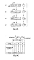
- the angular position of the time setting knob 28 corresponds to the time information to be displayed on the display section 26 without wide margin. Therefore, when the knob 28 is set at a transient position between adjacent levels or external noise affects the circuit, time display may fluctuate.
- the digital timer has such characteristics which cause, for the same displayed time, a different between the position of the time setting knob 28 during the course of incrementing the display and the position of the time setting knob 28 during the course of decrementing the display.
- the numeral display increase from “0010” to “0011” at the position of the knob 28 corresponding to level 11 and decrease from “0011” to "0010” at the position of the knob 28 corresponding to level 9.
- the rotation direction of the knob 28 is clockwise (display incrementing direction)
- time display appears corresponding to the final position of the knob 28 and when the rotation direction is counterclockwise (display decrementing direction)
- time display appears corresponding to previous position adjacent to final position of the knob 28.
- CPU 44 includes a memory circuit which has at least one specific storage area other than the above-mentioned storage area for the analog-to-digital (AID) converting operations.
- the digital signal of six-bit configuration is restored in the specific storage area after the signal is displayed on the display section 26.
- the digital signal corresponding to newly set position of the time setting knob 28 is compared with the previously stored digital signal by a comparator (not shown) of CPU 44 right after the completion of A/D converting operations. At this time, CPU 44 judges the rotation direction of the time setting knob 28 on the basis of the comparison results in CPU 44.
- the rotation direction is clockwise (display incrementing direction) and when the previous signal is larger than the new signal, the direction is counterclockwise (display decrementing position).
- the CPU 44 is arranged to provide the functions described with reference to Figures 13 and 14 in a way which would readily be apparent to a skilled worker and therefore need not be explained in detail.
- the numeral display on the display section 26 is still stable and is insensitive to incoming noise because of the above-mentioned characteristics.
- the electronic digital time is often used as a clock for displaying the present time of day when not used for cooking.
- the following will set forth the time adjustment operation of the second embodiment of the invention to adjust the present time. Referring to Figures 3, 4, 5 and 6, when the oven is not used for cooking, the digital timer is in the present time display mode and displays typically the present time, for example, "10:00" (10 o'clock) as shown in Figure 4(a).
- the time adjusting button 32 ( Figure 3) is first passed, causing time adjusting switch 32a ( Figure 6) to close intantaneously and the colon display element 26e changes from stationary lighting mode to flickering mode and hours digit display at left-hand two numeral display elements 26a, 26b changes to "00" and minutes digit display at right-hand two numeral display element 26c, 26d disappears.
- the time setting circuit 36 is ready to introduce time information in the hours digit positions.
- the time setting knob 28 is turned clockwise and "12" display appears on the display elements 26a, 26b, the time setting button 32 is pressed again and thus the hour digit setting is completed.
- time setting circuit 36 is ready to introduce time information in the minutes digit positions.
- the time setting knob 28 is further turned clockwise and "59" display appears on the display elements 26c, 26d
- the time setting button 32 is actuated again and thus minute digit setting is completed.
- the colon display segment 26e is returned from the flickering mode to the stationary lighting mode and clock operation is started again to update the adjusted present time display of 12:59.
- Time adjustment operation is executed in the above-mentioned manner. According to the third embodiment, it is possible to set time as long as the time setting circuit 36 produces at least sixty levels and these levels are converted into corresponding digital signals.
- Two time setting knobs 28 may be provided for setting time on left-hand display elements 26a, 26b and for setting time on right-hand display elements 26c, 26d.
- a programming button may be provided for programming said initiating time and/or terminating time in CPU 44.
- the programming button is first pressed instantaneously and the present time display disappears.
- the time "10:30” is set by rotating the time setting knob 28.
- the programming button is pressed instantaneously again and the set time display disappears.
- the time "11:00” is set by rotating the time setting knob 28 again.
- the present time display appears again on the display section 26.
- the microwave oven is automatically initiated for cooking and when the present time reaches to "11:00”, the cooking operation is automatically terminated.
- Setting of the initiating time and cooking time interval could also be possible.
Description
- This invention relates to an electronic digital timer and more particularly to an improved electronic digital timer capable of setting time in an analog fashion by operating time setting means and thereby controlling an operation of electric or electronic apparatus.
- In recent years, electronic digital timers have been used by combining them with various electric or electronic apparatus such as microwave ovens, digital tuning radio receivers or television receivers and video tape decks. Such electronic digital timers are used both as clocks, to inform users of the present time, and as interval timers, to set time intervals such as cooking time intervals for microwave ovens. A typical control panel for a microwave oven having a conventional electronic digital timer includes a display section which may comprise a plurality of seven-segment type light emitting diode display devices and a digit key pad which includes ten numeral keys for the decimal numerals 0-9 for changing the numeric display on the display section and being operated by setting, for example, time intervals for cooking. The panel may also include a cooking mode selection section having various cooking mode keys such as a "HIGH POWER" key for obtaining a high power microwave output from a magnetron and a "COOK" key for starting of the cooking operation. When the oven is in a normal condition, prior to cooking, a present time display appears on the display section to inform the user of the present time. That is, at this time, the electronic digital timer including the display section and the digit key section operates as an ordinary digital clock. If the user desires to cook by the high power output from the magnetron for 12 minutes and 34 seconds, for example, the "HIGH POWER" key on the cooking mode selection section is first selected and actuated. By this operation, the present time display disappears and a "0000" and "HIGH" displays appear on the display section. To set the cooking time interval for 12 minutes and 34 seconds, the "1" digit key is selected and actuated after the appearance of "0000" display. By this operation, the display section provides a display "0001". By sequential actuations of further digit keys "2", "3" and "4", the display pattern on the display section varies and "1234" display appears on the display section. Setting of the cooking time interval "1234" (12 minutes and 34 seconds) is completed. Under this condition, actuation of the "COOK" key starts the cooking which lasts for 12 minutes and 34 seconds.
- Setting cooking time by the use of a plurality of digit keys, however, has many disadvantages, among which are: (1) persons who have long experience with analog type timers (for example, mechanical rotary-type timers) often find it difficult to operate digit keys and often take a longer period of time to familiarize themselves with the digital timer having a plurality of digit keys; (2) when, for example, the user sets the wrong cooking time, they must set the correct cooking time again after putting the display on the display section back in its initial display condition "0000"; and (3) a large space is necessary to provide ten digit keys on the digit key pad of the panel.
- U.K. Patent Application GB-A-2019041 (Horstmann Gear Group Limited) discloses a programmable timer for individual control of a plurality of control functions which comprises a switch for each of the functions, each switch being settable by respective setting elements to be actuated at predetermined on and off time. The setting elements comprise sliders of linear potentiometers, which indicate the time settings in an analogue form. The output voltages from the linear potentiometers are fed to respective A-D convertors, and the corresponding switch is actuated when a digital display comparator detects coincidence between the value in the convertor and the time of day as shown by a display.
- A problem with this type of switching arrangement is that because the settings on the linear potentiometers can be varied in a continuous manner they may become set at transient positions between adjacent corresponding digital levels, or external noise may effect the circuitry and cause the digital output from the A-D convertor to fluctuate.
- An advantage of the present invention is that a "hysteresis" characteristic is provided in order to prevent fluctuation between adjacent digital levels.
- The present invention provides a cooker provided with an electronic digital timer for displaying time information on an electronic digital display device for the cooker, said electronic digital timer comprising:
- manually operative time setting means adjustable to provide selected time settings;
- a time setting circuit for producing an output voltage corresponding to the position of said time setting means;
- converting means for converting said output voltage of the time setting circuit into a digital signal corresponding to said output voltage; and
- display control means coupled to said electronic digital display device for producing display control signals in response to said digital signal for causing time information to be displayed on said electronic digital display device, characterised in that said cooker is a microwave cooker, and in that said converting means comprises a processing circuit and a comparator arranged to compare the digital signal corresponding to a newly set position of the time setting means with the digital signal corresponding to the last-displayed time information, whereby to determine whether the display is being incremented or decremented, said processing circuit being arranged to produce such characteristics which cause for a particular desired time display a difference between the position of the manually operative time setting means depending upon whether the display is being incremented or decremented, whereby a stable display is obtained.
- The digital display is preferably varied by operating a single control knob.
- In a particular embodiment of the invention, the time setting circuit includes a variable resistor having a movable arm, the position of the movable arm being controlled by the operation of the time setting means and the output voltage being determined by the selecting position of said movable arm. The converting means includes a digital-to-analog converter for converting a reference input digital signal into a corresponding reference output voltage, the comparator being arranged to compare the output voltage of the time setting circuit with the reference output voltage und to produce a comparator output signal indicative of the results of such comparison and the processing circuit being arranged to provide the reference input digital signal and being coupled to receive the comparator output signal for changing the reference digital signal in response to the comparator output signal and storing the comparator output signal as the digital corresponding to the comparator output voltage. The display control means includes a circuit for receiving the digital signal from the converting means after completion of the converting operation of the converting means and for changing the form of the digital signal to a signal capable of driving the electronic digital display device.
- For a particular time setting, there is a difference between the position of the time setting means during the course of incrementing the display and the position of the time setting means during the course of decrementing the display, whereby one particular time display is obtained within a range of the position of the time setting means and the time display is stably maintained even when noise affects the circuit of the timer.
- A second particular embodiment of the invention further includes time setting adjustment means for selection of a present time display mode and a time adjustment mode, the time adjustment mode being divided into an hours setting mode and a minutes setting mode, and the time setting circuit introduces time information in hours in the hours setting mode and introduces time information in minutes in the minutes setting mode.
- According to the invention as described above, the following benefits, among others, are obtained:
- (1) An improved electronic digital timer for a microwave oven, which is easy to operate, in particular, to persons who have long experience with analog-type timers,
- (2) An improved electronic digital timer for a microwave oven, in which it is easy to correct the time setting thereon,
- (3) A small size electronic digital timer for a microwave oven,
- (4) An improved electronic digital timer for a microwave oven having a display which is stable and not changed by noise,
- (5) An improved electronic digital timer for a microwave oven in which time is easy to adjust.
- In order that the present invention be more readily understood, embodiments thereof will now be described by way of example, with reference to the accompanying drawings, in which:-
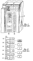
- Figure 1 is a front perspective view of a control panel portion of a microwave oven having a conventional electronic digital timer;
- Figures 2(a)-2(f) are representative of portions of the control panel of Figure 1 used for explanation of how cooking time is set by the use of the electronic digital timer of Figure 1;
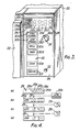
- Figure 3 is a front perspective view of a control panel portion of a microwave oven having a preferred embodiment of an electronic digital timer of the present invention;
- Figures 4(a)-4(d) are representative of portions of the control panel of Figure 3 used for explanation of how cooking time is set by the use of the electronic digital timer of Figure 3;
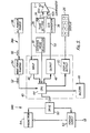
- Figure 5 is a schematic block diagram of one embodiment of circuitry used in the microwave oven of Figure 3 to control the electronic digital timer of the present invention.
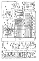
- Figure 6 is a schematic circuit diagram of portions of the circuitry of Figure 5;
- Figure 7 is an enlarged circuit diagram of portions of a digital-to-analog converter shown in Figure 6;
- Figure 8 is a graph used for explanation of operation of the digital-to-analog converter of Figure 7;
- Figure 9 is a flow diagram showing the sequence for setting the time in accordance with the embodiment of the electronic digital timer;
- Figures 10 to 12 are graphical representations used for explanation of Figure 9;
- Figure 13 is representative of the control panel of Figure 3 used for explanation of how cooking time is changed by the use of the electronic digital timer; and
- Figure 14 is a graphical representation used for explanation of Figure 13.
- Referring to Figure 1, there is shown a portion of a microwave oven including a
control panel 10 and a conventional electronic digital timer.Control panel 10 includes adisplay section 12 and adigit key section 14 which includes ten numerical keys for the decimal numerals 0-9. These digit keys are used for changing the numeric display on thedisplay section 12 and are operated for setting, for example, time intervals for cooking. Thepanel 10 also includes a cookingmode selection section 16 which includes various cooking mode keys, such as a "HIGH POWER" key for obtaining a high power microwave output from a magnetron and a "COOK" key for starting the cooking operation. - Referring to Figure 2, when the oven is in a normal condition, prior to cooking, a present time display (for example, 10 o'clock) appears on the
display section 12 as shown in Figure 2(a) to inform the user of the present time. That is, at this time, the electronic digital timer including thedisplay section 12 and thedigit key section 14 is operated as an ordinary digital clock. When the user desires to cook by the high power output from the magnetron, for example, for 12 minutes and 34 seconds, the "HIGH POWER" key on the cookingmode selection section 16 is first pressed. By this operation, the present time display disappears and "0000" and "HIGH" displays appear on thedisplay section 12 as shown in Figure 2(b). To set the cooking time interval of 12 minutes, 34 seconds, the "1" digit key is pressed after the appearance of "0000" display. By this operation, thedisplay section 12 provides a display "0001" as shown in Figure 2(c). By sequential pressing of further digit keys "2", "3" and "4", the display on thedisplay section 12 varies, as shown in Figures 2(d)-2(f) and "1234" display appears on thedisplay section 12 and setting of the cooking time interval "1234" (12 minutes and 34 seconds) is completed. Under this condition, pressing of the "COOK" key on the cookingmode selection section 16 starts the cooking which will automatically terminate at 12 minutes and 34 seconds. - Referring now to Figure 3, there is illustrated a microwave oven, generally designated by the
numeral 20, including an electronic digital timer constructed in accordance with and embodying the features of the present invention. The oven is conventional and includes a front-opening access door 22 to open and close an oven cooking cavity (not shown), which door is shown in Figure 3 in its fully closed position. - The
oven 20 has acontrol panel 24 provided on the front right side of the oven for providing control of the microwave oven cooking functions. Thecontrol panel 24 has adisplay section 26, atime setting knob 28, a cookingmode selection section 30 and atime adjusting button 32. Thedisplay section 26, thetime setting knob 28 and thetime adjusting button 32 are included in the electronic digital timer. Thedisplay section 26 may comprise an electronic character display device such as light emitting diodes, a fluorescent display tube, a liquid crystal display device or the like. In any case, the electronic character display device includes a plurality of seven-segment typenumeral display elements 26a-26d for time display, acolon display element 26e between thehour display elements minute display elements time setting knob 28 is mounted rotatably on thecontrol panel 24 for changing the time display pattern on the digitaltime display section 26 by rotatingknob 28. Index mark 28a on the top surface of theknob 28 points to a rotating position of theknob 28. The cookingmode selection section 30 comprises a plurality of cookingmode selection keys 30a-30f, such as a "LOW POWER" key 30b, for obtaining a low power microwave output from a magnetron, a - "GRILL" key 30c, for causing the microwave oven to be functioned as a grill, and a "COOK" key 30e for starting the cooking operation. These keys activate switches, as described below, which switches are rendered conductive or cut-off upon pressing said cooking mode selection keys. The
time adjusting button 32 is used to adjust the present time display on thedisplay section 26. - Figure 4 shows one way to operate the digital timer of Figure 3, in particular, to set a cooking time interval. When the
oven 20 is in the normal condition prior to cooking, the present time display (for example, "10:00" 10 o'clock) appears on the digitaltime display section 26, as shown in Figure 4(a), to inform the user of the present time. At this time,numeral display elements 26a-26d andcolon display element 26e are operated. When the user desires to cook by the low power microwave output for 12 minutes and 34 seconds, the "LOW POWER" key 30b on the cookingmode selection section 30 is first pressed. By this operation, the present time display disappears and the numbers "0000" and the work "LOW" appear on thetime display section 26, as indicated in Figure 4(b). That is, at this time,numeral display elements 26a-26d and "LOW" cookingmode display element 26g are operated. Under this condition, thetime setting knob 28 is turned clockwise and time from "0000" until "1240" (12 minutes and 40 seconds) displayed, as shown in Figure 4(c). Thetime setting knob 28 is turned counter-clockwise from the position of Figure 4(c) and until the time "1234" is displayed, as shown in Figure 4(d). Thus, the cooking time interval of 12minutes 34 seconds is set and displayed corresponding to the angular position of thetime setting knob 28. Under this condition, pressing of the "COOK" key 30e starts the cooking which will automatically terminate at 12 minutes and 34 seconds. - Figure 5 shows the schematic block diagram of circuitry for the above-mentioned operational sequence. This circuitry may be divided roughly into two portions. A
first portion 34A is used for converting an analog signal corresponding to the setting position of thetime setting knob 28 into a digital signal to be displayed on thedisplay section 26. Asecond portion 34B is used for controlling a cooking operation of themicrowave oven 20. - The principle of operation for the
first portion 34A will now be described. Atime setting circuit 36 produces an analog output voltage E corresponding to the angular position of thetime setting knob 28. A digital-to-analog (D/A)converter 38 produces an analog reference voltage V corresponding to a digital reference input signal Sd thereof, which is changed periodically by amicrocomputer 40. Acomparator 42 compares the output voltage E with the reference voltage V and produces a comparator output signal S which is "H" (binary "1") when output voltage E is higher than reference voltage V and which is "L" (binary "0") when output voltage E is lower than reference voltage V. The comparator output signal S is transferred to a central processing unit (CPU) 44 of themicrocomputer 40 through aninput port 46 and stored in a memory circuit (not shown) ofCPU 44. At the same time, on the basis of the stored signal,CPU 44 changes the reference input digital signal Sd through anoutput port 48. As a result, the reference voltage V is changed and the output voltage E is compared with the second reference voltage V in thecomparator 42. The second comparator output signal S is transferred toCPU 44 and stored in the memory circuit. On the basis of two stored signals ofCPU 44,CPU 44 changes the digital reference input signal Sd again for changing the reference voltage V. The output voltage E is compared with the third reference voltage V and the comparison result is stored in the memory circuit ofCPU 44. At the same time,CPU 44 changes the reference input digital signal Sd on the basis of three stored digital signals, and then a fourth comparison operation is executed. Similar operations are repeated several times, the number of times being determined by the number of converting bits of D/A converter 38. After the completion of the comparison operations, the stored digital signals of the memory circuit ofCPU 44 are transferred to thedisplay section 26 through adisplay output circuit 50 to be displayed as time information corresponding to the position of thetime setting knob 28. - The operation and structure will now be further described. When the user rotates the
time setting knob 28 and fixes it position, thetime setting circuit 36 produces an analog output voltage E corresponding to the angular position of the time -settingknob 28. Thetime setting circuit 36 may be constructed by use of a variable resistor. The output voltage E of thetime setting circuit 36 is applied to afirst input terminal 42a of acomparator 42, which may be a differential amplifier, an operation amplifier or other well known comparator circuit. Thesecond input terminal 42b of thecomparator 42 is supplied with an analog reference voltage V from a digital-to-analog (D/A)converter 38. The D/A converter 38 converts a reference input digital signal consisting of a plurality of bits (for example, 6 bits) from amicrocomputer 40 into the analog reference voltage V. Themicrocomputer 40 is programmed to sequentially change the reference signal six times during the comparison operation to obtain the binary equivalent of the analog output signal E. The first reference signal for all comparisons is preselected; the second to sixth reference signals are automatically changed on the basis of the result of the comparison of thecomparator 42. Thecomparator 42 compares the output voltage E from thetime setting circuit 36 with the analog reference voltage V from D/A converter 38 and produces the comparator output digital signal S. For example, when the output voltage E from thetime setting circuit 36 is higher than the analog reference voltage V from D/A converter 38, the comparator output signal S ofcomparator 42 will be "H", and when the output voltage E from thetime setting circuit 36 is lower than the analog reference voltage V from D/A converter 38, the comparator output signal S of thecomparator 42 will be "L". The comparator output signal S is applied to theinput port 46 of themicrocomputer 40. The output digital signal of theinput port 46 is applied toCPU 44 and stored in the memory circuit ofCPU 44. At the same time,CPU 44 produces an output digital signal on the basis of the stored signal thereof. The output digital signal ofCPU 44 is applied to the input terminals of D/A converter 38 as the reference input digital signal Sd through theoutput port 48 of themicrocomputer 40. The analog reference voltage V of D/A converter 38 is changed corresponding to the reference input digital signal Sd. The output voltage E of thetime setting circuit 36 is compared with the second reference voltage V in thecomparator 42. The second comparator output signal S is also stored in the memory circuit ofCPU 44 andCPU 44 changes the reference input digital signal Sd again on the basis of the two stored signals in the memory circuit for changing the reference voltage V. The output voltage E is compared with the third reference voltage V and the third comparator output signal S causesCPU 44 to change the reference input digital signal Sd of D/A converter 38. Similar operations are repeated, six times in all, after which the output voltage E of thetime setting circuit 36 is converted into a digital signal consisting of six bits which are stored in the memory circuit ofCPU 44. Therefore, the circuitry including D/A converter 38, thecomparator 42,CPU 44, theinput port 46 and theoutput port 48 is an analog-to-digital converter for converting the analog output voltage E from thetime setting circuit 36 into the digital signal to be displayed on thedisplay section 26 corresponding to said analog outputvoltage E. CPU 44 is controlled by a 50 Hz/60Hz clock pulse 52 produced by a waveform shaping circuit 54, whichcircuit 54 converts an ACcommercial power signal 56 having the frequency of 50 Hz/60 Hz from anAC power source 58 into a rectangular pulse wave. Theclock pulse 52 is used as a timing signal in the above-mentioned analog-to-digital converting operation and as a second signal (in case of 60 Hz pulse) for time display. This converting operation will be more detailed later. - The digital signal stored in the memory circuit of
CPU 44 is applied to thedisplay section 26 through thedisplay output circuit 50 of themicrocomputer 40, whichcircuit 50 may be a binary-to-decimal converting circuit. After the comparison operation is completed, the time display pattern on thedisplay section 26 is changed automatically by theclock pulse 52. For example, when the time display is the cooking time, it is counted down to zero, and when the time display is the present time, it is counted up in the usual way. - As stated above, the circuitry of Figure 5 includes the
second portion 34B for controlling the cooking operation which will now be described. TheCPU 44 also receives an order signal from the cookingmode selection section 30 and produces an output signal to display a cooking mode on thedisplay section 26. Furthermore, aCPU 44 produces a control signal to acontrol drive circuit 60 to start the cooking operation when the "COOK" key 30e on the cookingmode selection section 30 is actuated. At this time, thedrive circuit 60 controls apower supply circuit 62 to apply a power supply voltage to amagnetron circuit 64 during the time interval set by thetime setting knob 28. The time display of the set time interval is counted down after starting the cooking and the cooking operation is terminated when the cooking time display is returned to initial position "0000". At this time, abuzzer circuit 66 is operated by an order signal ofCPU 44 to inform the user of termination of cooking.CPU 44 also produces a control signal to control thedrive circuit 60 to change the microwave output power of the magnetron, depending upon whether the "HIGH POWER" key 30a or "LOW POWER" key 30b is operated. - Figure 6 shows the schematic circuit diagram of circuitry for some of the blocks of Figure 5. Referring to Figure 6, the
time setting circuit 36 comprises avariable resistor 36a, a fixedresistor 36b, connected in parallel withvariable resistor 36a, and a fixedresistor 36c having one end connected to one junction ofresistors resistors movable arm 36d ofvariable resistor 36a which provides the output voltage of thetime setting circuit 36 is connected to thepositive input terminal 42a ofcomparator 42. The output voltage of thetime setting circuit 36 is obtainable within the range of OV (when the movable arm of thevariable resistor 36a is connected to left side end thereof) and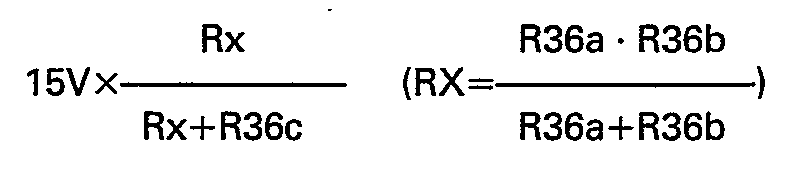
variable resistor 36a is connected to right side end thereof). - The D/A converter 38 (Figures 6 and 7) comprises a
buffer circuit 38a, aninput bias circuit 38b consisting of six resistors, each having one end connected to earth potential, and the other end connected to six input terminals Do―Dg of thebuffer circuit 38a respectively, and an outputladder network circuit 38c. The outputladder network circuit 38c consists of six resistors Ro-Rs, each having one end connected to six output terminals Ao―A5 of thebuffer circuit 38a respectively, five resistors R67-Rlo connected between the other ends of adjacent resistors Rs-Ro respectively, one resistor R11 connected between the junction of resistors Ro, R10 and earth potential and an output resistor R12 connected between the junction of resistors Ro, R6 and earth potential. The operation of the D/A converter 38 will be explained in detail below. - The
display section 26 comprises an electroniccharacter display device 26x (for example, a fluorescent display tube) having fournumeral display elements 26a-26d (fluorescent anode electrodes), thecolon display element 26e (fluorescent anode electrode) and four cookingmode display elements 26f-26i fluoresecent anode electrodes), acircuit 26y for driving the cathodes of saidfluorescent display tube 26x respectively having five resistors and acircuit 26z for driving the anodes of saidfluorescent display tube 26x respectively. Thefluorescent display tube 26x is a well known device used, for example, with electronic digital tape counters or electronic recording/reproducing level meters of tape decks, and display portions of disc type electronic calculators. The fundamental display operation thereof is also well known and operates by having electrons emitted from the heated cathode move to the anode. When the electrons collide with the anode, the fluorescent material applied on the surface of the anode is energized to emit light for display. Thecathode drive circuit 26y includes five resistors for heating the cathodes of thefluorescent tube 26x. One end of the resistors is connected to a power voltage -15V and the other end of the resistors is connected to the output terminals of thedisplay output circuit 50 of themicrocomputer 40. Theanode drive circuit 26z is used for applying appropriate voltage to the anodes of thefluorescent tube 26x. It includes seven resistors, one end of each being connected to a power voltage -15V and the other end of each being connected to the output terminals of thedisplay output circuit 50 of themicrocomputer 40. - The cooking
mode selection section 30 compriseskey switches 30a'-30f', corresponding to the cookingmode selection keys 30a-30f of Figure 3, anddiodes 30g-30i. These components form a 2x3 matrix circuit. The output terminals of the matrix circuit are connected toCPU 44 inmicrocomputer 40 and through resistors to earth potential. The input terminals of the matrix circuit are connected to thecathode drive circuit 26y. When a cooking mode key of Figure 3 is pressed, a corresponding key switch is closed for transferring a cooking mode order signal corresponding to the actuated key switch toCPU 44. - The
drive circuit 60 comprises at least two switchingcircuits first switching circuit 60a controls thepower supply circuit 62 in response to the output signal ofCPU 44 to supply a power voltage to themagnetron circuit 64 during the period of time when the output signal ofCPU 44 appears. Thesecond switching circuit 60b controls the output microwave power of the magnetron circuit 64 ("HIGH" or "LOW") in response to an output signal ofCPU 44 produced in response to the operations of powerselect switch mode selection section 30 ofcontrol panel 24. - The
power supply circuit 62 includes afuse 62a, power switches 62b, 62b', arelay switch 62c operated by the relay solenoid RL,, apower transformer 62d and a coolingfan motor 62e for cooling the magnetron of the magnetron circuit. Themagnetron circuit 64 includes themagnetron 64a, adiode 64b, capacitors 64c, 64d and arelay switch 64e operated by the relay solenoid RL2. When therelay switch 64e is closed, the oscillating frequency of themagnetron 64a is reduced by parallel connection of two capacitors 64c, 64d and "LOW" microwave power is supplied from themagnetron 64a. On the other hand, when therelay switch 64e is opened, the frequency is raised and "HIGH" microwave power is supplied from themagnetron 64a. Thebuzzer circuit 66 includes a buzzer 66a, a transistor 66b, a diode 66c and three resistors. - The operation for converting the analog output voltage E of the
time setting circuit 36 into the digital signal to be displayed on thedisplay section 26 will now be described. The principle of the operation, as stated above briefly with reference to Figure 6, is as follows; (1) by rotating the time setting knob 28 and fixing its position, the analog output voltage E, which corresponds to the angular position of the knob 28, is produced; (2) the first analog reference voltage V is produced by D/A converter 38, which voltage is predetermined by CPU 44; (3) the output voltage E is compared with the first reference voltage V by the comparator 42; (4) the comparator 42 produces a first comparator output signal S which is "H" when output voltage E is higher than reference voltage V and "L" when output voltage E is lower than reference voltage V; (5) the comparator output signal S is stored in the memory circuit of CPU 44 and causes CPU 44 to produce a signal for changing the reference input digital signal Sd of D/A converter 38 on the basis of the stored signal, thereby the reference voltage V is changed to the second reference voltage; (6) the output voltage E is compared with the second reference voltage V and the second comparator output signal S is stored in CPU 44; (7) on the basis of the first and second stored signals, CPU 44 changes the reference input digital signal Sd of D/A converter 38 and the reference voltage V is changed to the third reference voltage; (8) the output voltage E is compared with the third reference voltage V and similar operation is repeated; and (9) after the comparison operations are completed, six times in all, the six bits stored signal in CPU 44 is read out and transferred to the display section 26 through the display output circuit 50 to be displayed. - More specifically, referring first to Figures 7 and 8, the operation of D/
A converter 38 will be first described. Figure 7 shows an example of D/A converter 38 of a 6-bit configuration. Thebuffer circuit 38a of theconverter 38 is adapted such that it may deliver a given voltage Vc from each output terminal Ao―A5 when a "1" digital signal is received at the corresponding input terminal D0―D5 from themicrocomputer 40 and deliver OV when an "0" digital signal is received at the corresponding input terminal Do-D5. The output voltage Vout of theoutput ladder circuit 38c, therefore, bears a stepwise waveform corresponding to reference input digital signals as shown in Figure 8. That is, for example, when D/A converter 38 receives a binary digital signal "000000" (decimal "0") on input terminals D5 Do respectively from themicrocomputer 40, theconverter 38 produces 0 V (O level) at its output terminal. When theconverter 16 receives "000001" (decimal "1") on input terminals D5―D0 respectively, it produces a voltage Vout equal to V, (1 level, Figure 8). When the converter receives "000010" (decimal "2") on input terminals D5-Do respectively, it produces a voltage Vout equal to V2(=Vl+X; 2 level). When theconverter 38 receives "000011" (decimal "3") on output terminals D5―D0 respectively, it produces a voltage Vout equal to V3 (=V2+X; 3 level). When theconverter 38 receives "000100" (decimal "4") on input terminals D5-Do respectively, it produces a voltage Vout equal to V4 (=V3+X; 4 level). The rest is operated likewise, as summarized by reference to the examples in the following table:
- As is apparent from the above table, the output voltage from D/
A converter 38 varies stepwise from V, to V63 and theconverter 38 produces 64 different levels of the output voltage Vout corresponding to 64 different reference input digital signals Sd. These 64 output voltages are used as the reference voltage V (Figure 5) to be compared with the output voltage E of thetime setting circuit 36. - Figure 9 shows the flow diagram for explaining the operation for converting the output voltage of the
time setting circuit 36 into the digital signal to set the display output for thedisplay section 26. Figures 10, 11 and 12 illustrate the operations for converting the analog output voltage E of thetime setting circuit 36 corresponding to, for example, 63, 0, and 39 level from D/A converter 38 respectively into digital signals. In Figures 10 to 12, cross-hatched portion of the reference input shown a "1" signal and blank portions show a "0" signal. The principal converting sequences are as follows: (1) the analog output voltage E is first compared with the predetermined reference voltage V32 corresponding to the first preselected reference input digital signal "100000"; (2) if the first comparator output signal is "H", the reference voltage is changed to V48 corresponding to the reference input digital signal "110000", a first bit of which is stored "H" signals; (3) if the comparator output signal is "L", the reference voltage is changed to V,6 corresponding to the reference input digital signal "010000", a first bit of which is the stored "L" signal' (4) the analog output voltage E is compared with said second reference voltage, either V48 or V'6; (5) if the second comparator output signal is "H", the reference voltage is changed to V56 (when the first reference voltage is V48) corresponding to the reference input digital signal "111000" and the first and second bits of which are stored "HH" signals; (6) if the second comparator output signal is "H", the reference voltage is changed to V24 (when the first reference voltage is V16) corresponding to the reference input digital signal "011000", first and second bits of which are stored "LH" signals; (7) if the second comparator output signal is "L", the reference voltage is changed to V40 (when the first reference voltage is V48) corresponding to the reference input digital signal "101000", first and second bits of which are stored "HL" signals, or changed to V8 (when the first reference voltage is V'6) corresponding to the reference input digital signal "001000", first and second bits of which are stored "LL" signals; (8) the analog output voltage E is compared with the third reference signal V56, V24, V40 or Vs and similar operation is repeated; (9) after the comparison operation is repeated six times, CPU 44 detects the termination of the comparison operation; (10) six bits stored signal is read out from CPU 44 and transferred to the display section 26 through the display output circuit 50; and (11) the stored signal is displayed on the display section 26 as corresponding time information. - These sequences will now be explained in more detail.
- Referring to Figures 5 to 10, the output voltage E of the
time setting circuit 36 is higher than or equal to the reference voltage V63 from D/A converter 38. Infirst step 68 of Figure 9 for setting of reference voltage, the output signal of the output port 48 (the reference input digital signal Sd of D/A converter 38) is set automatically as "100000" having "1" at the most significant bit (MSB) position and "0" at the other bit positions. By this setting, the reference voltage V32 oflevel 32 is produced from D/A converter 38 as a first reference voltage.Second step 70 of Figure 9 is a standby step to accommodate response time of the circuit. Inthird step 72 of Figure 9 for comparison of E and V, the output voltage E of thetime setting circuit 36 corresponding to substantially 63 level is compared with said first reference voltage V32 by thecomparator 42 and thecomparator 42 produces "H" comparator output signal. Infourth step 74 of Figure 9 for transferring the comparison result, said "H" comparator output signal is transferred to theinput port 46. Infifth step 76 of Figure 9 for storing the comparison result, the comparator output signal "H" is stored in the memory circuit ofCPU 44 at first store position (MSB position) thereof as "1". Insixth step 78 of Figure 9 for sensing the completion of all comparison operations (six times),CPU 44 checks whether six times comparison operations are completed or not. In this case,CPU 44 decides to return the operation tofirst step 68 because the checking result is negative. The operation illustrated so far is conducted during time T, as shown in Figure 10. - Similar operation is conducted during time T2 after T,. In the
step 68 of second time interval, the reference input digital signal of D/A converter 38 is set as "110000", in which MSB "1" remains without change because comparison result was "H" ("1"), second bit is set newly as "1" and the rest remain as "0". By this setting, the voltage of level 48 (V48) is produced from D/A converter 38 as a second reference voltage. In thestep 72 afterstandby step 70, substantially 63 level output voltage E of thetime setting circuit 36 is compared with the second reference voltage of level 48 (V48). In this case, since the output voltage E of thetime setting circuit 36 is substantiallylevel 63, the comparison result is "H", as above;steps CPU 44 at second store position (second significant bit position) as "1". Operation is returned to thestep 68 again through thestep 78. - Similar operation is conducted during time T3 of Figure 10 after T2. In the
step 68 of third time interval, the reference input digital signal of D/A converter 38 is set as "111000", in which upper two bits remains as "1", and the third bit is set newly as "1" and the rest remain as "0". By this setting, the voltage of level 56 (V56) is produced from theconverter 38 as a third reference signal. The substantially 63 level output voltage E of thetime setting circuit 36 is compared with the third reference voltage of level 56 (V56) and "H" level comparator output signal is produced, as above. The third "H" level comparator output signal is stored in the memory circuit at third store position (third significant bit position) as "1" and operation is returned to thestep 68 again. - The above-mentioned operation is repeated at times T4 and T5 (Figure 10) because the 63 level output voltage E of the
time setting circuit 36 is higher than the voltage of level 60 ("111100") or level 62 ("111110"). In the case of time T6, steps 68-76 are the same as above because the output voltage E of thetime setting circuit 36 is also higher than the voltage of level 63 ("111111"). However, in thestep 78 at time T6,CPU 44 detects completion of the comparison operation for all six bits. Therefore, data "111111" stored in the memory circuit ofCPU 44 is read out in thestep 80 for reading out the stored signal and time (for example, cooking time interval) corresponding to the output voltage E of level 63 ("111111") is displayed on thedisplay section 26 in thestep 82 for displaying the time information. - The next example is the detection of 39 level as shown in Figure 12. In this case, the output voltage of the
time setting circuit 36 is within the range of level 39 andlevel 40 from D/A converter 38. Infirst step 68 of Figure 9, the output signal of the output port 48 (the reference input digital signal of D/A converter 38) us automatically set as "100000", as above. Inthird step 72 throughstandby step 70 of Figure 9, the reference voltage of level 32 (V32) from theconverter 38 is compared with the output voltage E of thetime setting circuit 36 corresponding to substantially level 39 by thecomparator 42 and thecomparator 42 produces "H" comparator output signal.Steps 7478 are the same as mentioned above. In thestep 68 of second time interval, the reference voltage of level 48 (V48) is produced and the comparison operation is conducted by thecomparator 42. In this case, the output voltage E of the time setting circuit 36 (about level 39) is lower than said reference voltage oflevel 48. Therefore, thecomparator 42 produces "L" comparator output signal in thestep 72 of Figure 9. Because of "L" level output, thestep 84 for storing the comparator output signal occurs after thestep 4 operation. In thisstep 84, the "L" level is stored in the memory circuit ofCPU 44 at second store position (second significant bit position) as "0" and operation is returned to thestep 68 again through thestep 78. - In the
step 68 of the third time interval, the reference input digital signal of D/A converter 38 is set as "101000", in which MSB "1" remains without change, second significant bit is changed from "1" to "0" because second comparison result was "L", third bit is newly set as "1" and the rest remain as "0". By this setting, the voltage of level 40 (V40) is produced from theconverter 38 as a third reference voltage. Since this reference voltage oflevel 40 is also higher than the output voltage E (about level 39) of thetime setting circuit 36, thecomparator 42 produces "L" output signal and steps 72, 74, 84 and 78 are repeated again in that order. - In the
step 68 of fourth time interval, the reference input digital signal of D/A converter 38 is set as "100100" and 36 level reference voltage (V36) is produced from D/A converter 38. In this case, since thelevel 36 reference voltage is lower than the output voltage E (about level 39) of thetime setting circuit 36, thecomparator 42 produces "H" output signal and step 72, 74, 76 and 78 are repeated in that order. - The above-mentioned operation (steps 72-74-76-78) is repeated at times T5 and To of Figure 12 because each 38, 39 level reference voltages is lower than the output voltage E of the
time setting circuit 36. Instep 78 of time T6 (Figure 12),CPU 44 detects completion of the comparison operation for all six bits. Therefore, data "100111" stored in the memory circuit ofCPU 44 is read out in thestep 80 and time corresponding to the output voltage E of level 39 ("100111") is displayed on thedisplay section 26 in thestep 82. - Figure 11 illustrates the detection operation of 0 level. As is obvious from the foregoing, in this case, the reference voltage is changed as follows: first reference voltage level 32 ("100000"), second level 16 ("010000"), third level 8 ("001000"), fourth level 4 ("000100"), fifth level 2 ("000010") and sixth level 1 ("000001"). Since all of these reference voltages are higher than the output voltage E (0 level) of the
time setting circuit 36, thecomparator 42 produces "L" at all times T,- Ts of Figure 11 and time corresponding to 0 level ("000000") is displayed on thedisplay section 26. - According to the above-mentioned apparatus it is possible to display 64 different time informations on the
display section 26. For example, if each level of 64 different reference voltages corresponds to one minute of cooking time interval, cooking time interval display from 0 minutes until 63 minutes would be possible. If each level corresponds to ten seconds, the display from 0 second until 630 seconds (10 minutes, 30 seconds) would be possible. If the time corresponding to each level is changed appropriately or the number of levels is increased to more than 64 or decreased to less than 64, arbitrary time display would be possible. - While the
variable resistor 36a is used in thetime setting circuit 36, thetime setting circuit 36 may be constructed by the use of, for example, a rotary switch having 64 terminals connected to resistors or a slidable variable resistor instead of rotaryvariable resistor 36a. - While four
numeral display elements 26a-26d are all used for time display (Figure 4), the two left-side elements side elements - In the above-mentioned circuitry in which four
numeral display elements 26a-26d are all used for time display, if a switch for selecting minute display mode or second display mode is provided, a change of minute display or second display would be possible separately. The same advantages would also be obtained when two time setting knobs (one being used for setting minutes, the other for setting seconds) are provided. - In the above-mentioned circuitry, the angular position of the
time setting knob 28 corresponds to the time information to be displayed on thedisplay section 26 without wide margin. Therefore, when theknob 28 is set at a transient position between adjacent levels or external noise affects the circuit, time display may fluctuate. To solve this problem, the digital timer has such characteristics which cause, for the same displayed time, a different between the position of thetime setting knob 28 during the course of incrementing the display and the position of thetime setting knob 28 during the course of decrementing the display. - The following will further set forth this characteristic with reference to Figures 13 and 14. In Figure 13(a), "0000" is displayed corresponding to the initial angular position (level 0) of the
time setting knob 28. When theknob 28 is turned clockwise as shown by an arrow in Figure 13(a), "0010" is displayed corresponding to the angular position (level 10 in Figure 14) of theknob 28 shown in Figure 13(b). Then, theknob 28 is further turned clockwise, as shown by an arrow in Figure 13(b) to the extent corresponding to an increment of the numeral display by 1, as designated from Figure 13(b) to 13(c), whereupon the display will be "0011" (Figure 13(c)) corresponding to the angular position (level 11 in Figure 14) of theknob 28. In this case, the increment operation occurs at point A (betweenlevels 10 and 11) in Figure 14. On the contrary, if theknob 28 is turned counter- clockwise as shown by an arrow in Figure 13(c), the display is decremented by 1 as shown in Figure 13(d). Then, "0010" appears again on thedisplay section 26. The decrementation occurs at point B (betweenlevels 9 and 10) of Figure 14 and said time display "0010" is continued to be displayed at the angular position of theknob 28 corresponding tolevel 9. As is apparent from the foregoing, there is established a difference between the angular position of thetime setting knob 28 during the course of incrementing the time display and the position of thetime seting knob 28 during the course of decrementing the time display. In other words, in Figure 14, the numeral display increase from "0010" to "0011" at the position of theknob 28 corresponding tolevel 11 and decrease from "0011" to "0010" at the position of theknob 28 corresponding tolevel 9. At the position of theknob 28 corresponding to level 10 betweenlevels knob 28 is rotated clockwise, "0010" is displayed and when theknob 28 is rotated counterclockwise, "0011" is displayed. Therefore, when the rotation direction of theknob 28 is clockwise (display incrementing direction), time display appears corresponding to the final position of theknob 28 and when the rotation direction is counterclockwise (display decrementing direction), time display appears corresponding to previous position adjacent to final position of theknob 28. - The above-mentioned characteristics may be implemented by appropriate programming of
CPU 44. For example,CPU 44 includes a memory circuit which has at least one specific storage area other than the above-mentioned storage area for the analog-to-digital (AID) converting operations. The digital signal of six-bit configuration is restored in the specific storage area after the signal is displayed on thedisplay section 26. The digital signal corresponding to newly set position of thetime setting knob 28 is compared with the previously stored digital signal by a comparator (not shown) ofCPU 44 right after the completion of A/D converting operations. At this time,CPU 44 judges the rotation direction of thetime setting knob 28 on the basis of the comparison results inCPU 44. When the previous signal is smaller than the new signal, the rotation direction is clockwise (display incrementing direction) and when the previous signal is larger than the new signal, the direction is counterclockwise (display decrementing position). TheCPU 44 is arranged to provide the functions described with reference to Figures 13 and 14 in a way which would readily be apparent to a skilled worker and therefore need not be explained in detail. - According to this invention, even if the
time setting knob 28 is stopped at a transient position between two adjacent levels and comparison result fluctuates, the numeral display on thedisplay section 26 is still stable and is insensitive to incoming noise because of the above-mentioned characteristics. - As stated above, the electronic digital time is often used as a clock for displaying the present time of day when not used for cooking. The following will set forth the time adjustment operation of the second embodiment of the invention to adjust the present time. Referring to Figures 3, 4, 5 and 6, when the oven is not used for cooking, the digital timer is in the present time display mode and displays typically the present time, for example, "10:00" (10 o'clock) as shown in Figure 4(a). At this time, when the user desires to adjust the present time to "12:59", the time adjusting button 32 (Figure 3) is first passed, causing
time adjusting switch 32a (Figure 6) to close intantaneously and thecolon display element 26e changes from stationary lighting mode to flickering mode and hours digit display at left-hand twonumeral display elements numeral display element time setting circuit 36 is ready to introduce time information in the hours digit positions. When thetime setting knob 28 is turned clockwise and "12" display appears on thedisplay elements time setting button 32 is pressed again and thus the hour digit setting is completed. In this case, however, clock operation is still stopped and will not change until the minute digit setting being completed. At the same time of the second actuation of thetime setting button 32, minute digit display at thedisplay elements time setting circuit 36 is ready to introduce time information in the minutes digit positions. When thetime setting knob 28 is further turned clockwise and "59" display appears on thedisplay elements time setting button 32 is actuated again and thus minute digit setting is completed. At the same time, thecolon display segment 26e is returned from the flickering mode to the stationary lighting mode and clock operation is started again to update the adjusted present time display of 12:59. Time adjustment operation is executed in the above-mentioned manner. According to the third embodiment, it is possible to set time as long as thetime setting circuit 36 produces at least sixty levels and these levels are converted into corresponding digital signals. - As stated above, the procedure, like the above-mentioned time adjustment procedure, could also be used as cooking time setting procedure. Two
time setting knobs 28 may be provided for setting time on left-hand display elements hand display elements - While the above-mentioned embodiments indicate the digital timers used for clocks and as interval timers, the digital timers may also be used for setting an initiating cooking time and/or terminating cooking time. In this case, a programming button may be provided for programming said initiating time and/or terminating time in
CPU 44. For example, at 9:00 (present time), when the user desires to initiate the cooking at 10:30 and terminate it at 11:00, the programming button is first pressed instantaneously and the present time display disappears. The time "10:30" is set by rotating thetime setting knob 28. The programming button is pressed instantaneously again and the set time display disappears. The time "11:00" is set by rotating thetime setting knob 28 again. Under these circumstances, when the "COOK" key is pressed, the present time display appears again on thedisplay section 26. When the present time reaches to the set time "10:30", the microwave oven is automatically initiated for cooking and when the present time reaches to "11:00", the cooking operation is automatically terminated. Setting of the initiating time and cooking time interval could also be possible. - While there have been described what are at present invention considered to be preferred embodiments of the invention, it will be understood that within the scope of the invention as defined by the claims various modifications may be made therein, for example: (1) to replace the rotary
variable resistor 36a with the rotary switch or slidable variable resistor; (2) use of only two numeral display elements of thedisplay device 26x for time display (3) providing two time setting knobs for setting time on two left-hand numeral display elements and for setting time on two right-hand display elements.
Claims (7)
Applications Claiming Priority (4)
| Application Number | Priority Date | Filing Date | Title |
|---|---|---|---|
| JP4824/81 | 1981-01-13 | ||
| JP56004825A JPS57118183A (en) | 1981-01-13 | 1981-01-13 | Digital timer for electronic apparatus |
| JP4825/81 | 1981-01-13 | ||
| JP482481A JPS57118182A (en) | 1981-01-13 | 1981-01-13 | Digital timer for household electric apparatus |
Publications (2)
| Publication Number | Publication Date |
|---|---|
| EP0056335A1 EP0056335A1 (en) | 1982-07-21 |
| EP0056335B1 true EP0056335B1 (en) | 1986-11-26 |
Family
ID=26338666
Family Applications (1)
| Application Number | Title | Priority Date | Filing Date |
|---|---|---|---|
| EP82300185A Expired EP0056335B1 (en) | 1981-01-13 | 1982-01-13 | Cooker provided with an electronic digital timer |
Country Status (5)
| Country | Link |
|---|---|
| US (1) | US4504716A (en) |
| EP (1) | EP0056335B1 (en) |
| AU (1) | AU538241B2 (en) |
| CA (1) | CA1181600A (en) |
| DE (1) | DE3274504D1 (en) |
Cited By (1)
| Publication number | Priority date | Publication date | Assignee | Title |
|---|---|---|---|---|
| EP2336641A1 (en) | 2009-12-17 | 2011-06-22 | Electrolux Home Products Corporation N.V. | A clock timer for a domestic appliance |
Families Citing this family (18)
| Publication number | Priority date | Publication date | Assignee | Title |
|---|---|---|---|---|
| DE3329300A1 (en) * | 1983-08-12 | 1985-02-28 | Bosch-Siemens Hausgeräte GmbH, 7000 Stuttgart | ARRANGEMENT FOR CONTROLLING HEATING PERIODS AND HEATING PERFORMANCE FOR COOKERS |
| JPS60140295A (en) * | 1983-12-27 | 1985-07-25 | 三洋電機株式会社 | Controller |
| US4615014A (en) * | 1984-04-16 | 1986-09-30 | Lincoln Manufacturing Company, Inc. | Bake time display for cooking oven |
| JPS60253738A (en) * | 1984-05-29 | 1985-12-14 | Toshiba Corp | Heating cooking device |
| US4647915A (en) * | 1984-10-29 | 1987-03-03 | Tektronix, Inc. | Method and apparatus for adjusting displayed oscilloscope parameters |
| US4624578A (en) * | 1985-12-02 | 1986-11-25 | Green David L | Rental contract timer system |
| JP2848595B2 (en) * | 1986-04-09 | 1999-01-20 | 株式会社東芝 | Cooking device |
| KR940000314B1 (en) * | 1989-12-28 | 1994-01-14 | 주식회사 금성사 | Standing time displaying method for electronic range |
| KR930003116A (en) * | 1991-07-15 | 1993-02-24 | 강진구 | Schedule recording method using digital clock |
| JPH06217219A (en) * | 1993-01-14 | 1994-08-05 | Toshiba Corp | Time diplay device |
| JP3219716B2 (en) * | 1997-07-18 | 2001-10-15 | 三洋電機株式会社 | Cooking device |
| AU747488B2 (en) * | 1998-07-31 | 2002-05-16 | Resmed Limited | Graphical display |
| AUPP496198A0 (en) | 1998-07-31 | 1998-08-20 | Resmed Limited | Switches with graphical display |
| MY126873A (en) * | 2000-01-07 | 2006-10-31 | Vasu Tech Ltd | Configurable electronic controller for appliances |
| AU7174700A (en) | 2000-05-04 | 2001-11-08 | Vasu Tech Limited | Configurable electronic controller |
| US20040004807A1 (en) * | 2002-07-02 | 2004-01-08 | Lg Electronics Inc. | Combined microwave oven and radio |
| US8136442B2 (en) * | 2005-08-30 | 2012-03-20 | Turbochef Technologies, Inc. | Selection systems and methods |
| US20100195447A1 (en) * | 2009-02-05 | 2010-08-05 | Gb11, Llc | Alarm clock and a system and a method to wake a user |
Family Cites Families (10)
| Publication number | Priority date | Publication date | Assignee | Title |
|---|---|---|---|---|
| US3731302A (en) * | 1970-09-14 | 1973-05-01 | Phillips Petroleum Co | Digital/analog conversion system |
| GB1441459A (en) * | 1972-06-27 | 1976-06-30 | Matsushita Electric Ind Co Ltd | Device for controlling electrical appliances |
| DE2626327C3 (en) * | 1976-06-11 | 1980-08-14 | Siemens Ag, 1000 Berlin Und 8000 Muenchen | Digital, electrical measuring device |
| JPS5332651A (en) * | 1976-09-07 | 1978-03-28 | Yokogawa Hokushin Electric Corp | Analog operation unit |
| DE2658105B2 (en) * | 1976-12-22 | 1979-03-22 | Diehl Gmbh & Co, 8500 Nuernberg | Contact controlled pulse generator |
| GB2019041B (en) * | 1978-04-03 | 1982-07-28 | Horstmann Gear Group Ltd | Programmable timer |
| DE2835200C3 (en) * | 1978-08-11 | 1984-06-28 | Diehl GmbH & Co, 8500 Nürnberg | Method and circuit for setting an electronic digital display of a target duration |
| US4367387A (en) * | 1979-05-15 | 1983-01-04 | Sanyo Electric Co., Ltd. | Electronic controlled heat cooking apparatus |
| DE2922621C2 (en) * | 1979-06-02 | 1985-10-31 | Braun Ag, 6000 Frankfurt | Electronic clock with alarm device |
| GB2069192A (en) * | 1980-01-24 | 1981-08-19 | Plessey Co Ltd | Programmable timed control arrangements |
-
1981
- 1981-12-31 US US06/336,043 patent/US4504716A/en not_active Expired - Lifetime
- 1981-12-31 AU AU79150/81A patent/AU538241B2/en not_active Ceased
-
1982
- 1982-01-12 CA CA000393968A patent/CA1181600A/en not_active Expired
- 1982-01-13 EP EP82300185A patent/EP0056335B1/en not_active Expired
- 1982-01-13 DE DE8282300185T patent/DE3274504D1/en not_active Expired
Cited By (2)
| Publication number | Priority date | Publication date | Assignee | Title |
|---|---|---|---|---|
| EP2336641A1 (en) | 2009-12-17 | 2011-06-22 | Electrolux Home Products Corporation N.V. | A clock timer for a domestic appliance |
| WO2011072868A1 (en) | 2009-12-17 | 2011-06-23 | Electrolux Home Products Corporation N.V. | A clock timer for a domestic appliance |
Also Published As
| Publication number | Publication date |
|---|---|
| EP0056335A1 (en) | 1982-07-21 |
| US4504716A (en) | 1985-03-12 |
| AU538241B2 (en) | 1984-08-02 |
| DE3274504D1 (en) | 1987-01-15 |
| CA1181600A (en) | 1985-01-29 |
| AU7915081A (en) | 1982-07-22 |
Similar Documents
| Publication | Publication Date | Title |
|---|---|---|
| EP0056335B1 (en) | Cooker provided with an electronic digital timer | |
| US5352874A (en) | Apparatus for changing cooking control data of automatic cookers | |
| EP0019276B1 (en) | Heating apparatus with programmable timer | |
| US4918293A (en) | Electrically operated appliance controls and methods of making the same | |
| US4761540A (en) | Electrically operated appliance controls and methods of making the same | |
| US4225776A (en) | Electronic digital time display apparatus | |
| US20060047344A1 (en) | Methods and apparatus for operating a speedcooking oven | |
| GB2160694A (en) | Cooking apparatus | |
| DE3018298C2 (en) | Electronically controlled cooking device with pre-selected cooking time | |
| US4695711A (en) | Electrically operated appliance controls and methods of making the same | |
| JPS6237787B2 (en) | ||
| GB1602051A (en) | Motor speed adjusting apparatus | |
| US4406945A (en) | Heating apparatus with numerical display | |
| US4920365A (en) | Electronic digital timepiece having a separate key for controlling the switching of the display from standard to daylight savings time | |
| US4636621A (en) | Electrically operated appliance controls and methods of making the same | |
| US4488089A (en) | Fluorescent indicator tube driving circuit | |
| EP0289001B1 (en) | A tuner with a timepiece | |
| US4707145A (en) | Electronic timepiece | |
| US4394557A (en) | Electronic controlled heat cooking apparatus | |
| US4658186A (en) | Control apparatus for fluorescent display tube | |
| US4279029A (en) | Electronic timepiece | |
| US20020005669A1 (en) | Time controls with enhanced timing range | |
| KR200144767Y1 (en) | Microwave oven with power level control | |
| JPS6345015B2 (en) | ||
| KR970005121B1 (en) | Display apparatus |
Legal Events
| Date | Code | Title | Description |
|---|---|---|---|
| PUAI | Public reference made under article 153(3) epc to a published international application that has entered the european phase |
Free format text: ORIGINAL CODE: 0009012 |
|
| AK | Designated contracting states |
Designated state(s): CH DE FR GB NL |
|
| 17P | Request for examination filed |
Effective date: 19821221 |
|
| GRAA | (expected) grant |
Free format text: ORIGINAL CODE: 0009210 |
|
| AK | Designated contracting states |
Kind code of ref document: B1 Designated state(s): CH DE FR GB LI NL |
|
| ET | Fr: translation filed | ||
| REF | Corresponds to: |
Ref document number: 3274504 Country of ref document: DE Date of ref document: 19870115 |
|
| PLBE | No opposition filed within time limit |
Free format text: ORIGINAL CODE: 0009261 |
|
| STAA | Information on the status of an ep patent application or granted ep patent |
Free format text: STATUS: NO OPPOSITION FILED WITHIN TIME LIMIT |
|
| 26N | No opposition filed | ||
| PGFP | Annual fee paid to national office [announced via postgrant information from national office to epo] |
Ref country code: GB Payment date: 19950104 Year of fee payment: 14 |
|
| PGFP | Annual fee paid to national office [announced via postgrant information from national office to epo] |
Ref country code: FR Payment date: 19950110 Year of fee payment: 14 Ref country code: DE Payment date: 19950110 Year of fee payment: 14 |
|
| PGFP | Annual fee paid to national office [announced via postgrant information from national office to epo] |
Ref country code: CH Payment date: 19950113 Year of fee payment: 14 |
|
| PGFP | Annual fee paid to national office [announced via postgrant information from national office to epo] |
Ref country code: NL Payment date: 19950131 Year of fee payment: 14 |
|
| REG | Reference to a national code |
Ref country code: GB Ref legal event code: 746 Effective date: 19950224 |
|
| REG | Reference to a national code |
Ref country code: FR Ref legal event code: D6 |
|
| PG25 | Lapsed in a contracting state [announced via postgrant information from national office to epo] |
Ref country code: GB Effective date: 19960113 |
|
| PG25 | Lapsed in a contracting state [announced via postgrant information from national office to epo] |
Ref country code: LI Effective date: 19960131 Ref country code: CH Effective date: 19960131 |
|
| PG25 | Lapsed in a contracting state [announced via postgrant information from national office to epo] |
Ref country code: NL Effective date: 19960801 |
|
| GBPC | Gb: european patent ceased through non-payment of renewal fee |
Effective date: 19960113 |
|
| REG | Reference to a national code |
Ref country code: CH Ref legal event code: PL |
|
| PG25 | Lapsed in a contracting state [announced via postgrant information from national office to epo] |
Ref country code: FR Effective date: 19960930 |
|
| NLV4 | Nl: lapsed or anulled due to non-payment of the annual fee |
Effective date: 19960801 |
|
| PG25 | Lapsed in a contracting state [announced via postgrant information from national office to epo] |
Ref country code: DE Effective date: 19961001 |
|
| REG | Reference to a national code |
Ref country code: FR Ref legal event code: ST |