EP0056169A1 - Water tight seal between two concrete elements - Google Patents
Water tight seal between two concrete elements Download PDFInfo
- Publication number
- EP0056169A1 EP0056169A1 EP81200017A EP81200017A EP0056169A1 EP 0056169 A1 EP0056169 A1 EP 0056169A1 EP 81200017 A EP81200017 A EP 81200017A EP 81200017 A EP81200017 A EP 81200017A EP 0056169 A1 EP0056169 A1 EP 0056169A1
- Authority
- EP
- European Patent Office
- Prior art keywords
- sealing strip
- watertight seal
- sealing surface
- wedge
- watertight
- Prior art date
- Legal status (The legal status is an assumption and is not a legal conclusion. Google has not performed a legal analysis and makes no representation as to the accuracy of the status listed.)
- Ceased
Links
Images


Classifications
-
- F—MECHANICAL ENGINEERING; LIGHTING; HEATING; WEAPONS; BLASTING
- F16—ENGINEERING ELEMENTS AND UNITS; GENERAL MEASURES FOR PRODUCING AND MAINTAINING EFFECTIVE FUNCTIONING OF MACHINES OR INSTALLATIONS; THERMAL INSULATION IN GENERAL
- F16L—PIPES; JOINTS OR FITTINGS FOR PIPES; SUPPORTS FOR PIPES, CABLES OR PROTECTIVE TUBING; MEANS FOR THERMAL INSULATION IN GENERAL
- F16L27/00—Adjustable joints, Joints allowing movement
- F16L27/10—Adjustable joints, Joints allowing movement comprising a flexible connection only, e.g. for damping vibrations
- F16L27/1017—Joints with sleeve or socket
-
- F—MECHANICAL ENGINEERING; LIGHTING; HEATING; WEAPONS; BLASTING
- F16—ENGINEERING ELEMENTS AND UNITS; GENERAL MEASURES FOR PRODUCING AND MAINTAINING EFFECTIVE FUNCTIONING OF MACHINES OR INSTALLATIONS; THERMAL INSULATION IN GENERAL
- F16L—PIPES; JOINTS OR FITTINGS FOR PIPES; SUPPORTS FOR PIPES, CABLES OR PROTECTIVE TUBING; MEANS FOR THERMAL INSULATION IN GENERAL
- F16L27/00—Adjustable joints, Joints allowing movement
- F16L27/10—Adjustable joints, Joints allowing movement comprising a flexible connection only, e.g. for damping vibrations
- F16L27/1025—Abutment joints
Definitions
- the invention relates to a watertight seal between two adjoining, prefabricated culvert elements, tunnel sections, sewer pipes or similar concrete elements, in which an elastic sealing strip is sandwiched between a sealing surface of a socket of one concrete element and a sealing surface of a wedge of the other concrete element enveloped by the socket, in which one sealing surface has a groove retaining the elastic sealing strip in an axial direction and the other sealing surface - viewed in the direction from the bonded end of the wedge towards the free end of the wedge - is converging and in which the profile of the sealing strip, in the unstressed state, has a ridge directed towards the converging sealing surface and adjoining a profile face diverging in the direction of convergence of the converging sealing surface.
- Such a seal is known from GB - A - PS 464,087.
- the material of the sealing strip may be jammed between the edge of the groove and the opposite surface, so that the sealing strip may be damaged and/or the socket may break down due to excessive radial stress.
- the watertightness is not ensured, because the radial contact pressure of the sealing strip on the sealing surfaces is highly dependent on the degree of flattening of the sealing strip, which varies with the noncircu- larity, the accuracy of dimensions and aligning defects.
- the aligning defects are involved in mounting operations and/or subsidence of the subsoil supporting the concrete elements.
- the invention has for its object to improve the watertight seal of the kind set forth in the preamble.
- at least one channel is made in the elastic material of the sealing strip, whilst the sealing strip has a transverse profile, such that, when the two conorete elements are joined, material of the sealing strip shifts in a converging direction of the converging sealing surface.
- the channel is preferably located on the side of the sealing strip remote from the groove edge.
- the sealing strip also has a stop sleeve disposed outside of the groove, this stop sleeve operates as a bed absorbing the high forces with which the concrete elements bear one on the other. Thus the seal is relieved of these high bearing forces, so that in the area of the sealing surfaces the sealing strip can be flexible and deformable over a large radial distance.
- the invention furthermore improves a watertight seal between two adjoining, prefabricated culvert elements, tunnel sections or suchlike concrete elements, in which an elastic sealing strip is sandwiched between a sealing surface of a socket of one concrete element and a sealing surface of a wedge of the other concrete element enveloped by the socket, at least one sealing surface having a groove accommodating the elastic sealing strip, so that particularly in the event of appreciable and/or frequent relative axial displacements of the concrete elements the watertightness remains guaranteed.
- this is achieved by providing the sealing strip with a first anchor ring ring accommodated in a watertight relationship in a groove of one sealing surface, with a second anchor ring held in watertight relationship in a groove of the other sealing surface and with a sleeve arranged between the two anchor rings and allowing a relative, axial displacement of the anchor rings.
- each anchor ring ensures the watertightness with respect to the associated concrete element, whilst the sleeve bridges in a watertight manner the axial distance between the anchor rings irrespective of changes of said distance.
- the anchor ring When one of the grooves is wedge-shaped in an axial direction, the anchor ring can be readily arranged in sealing relationship with the groove, particularly so when the wedge-shaped groove of one concrete element - viewed in an axial direction - is disposed opposite an edge of the other concrete element.
- the watertightness can be readily obtained in the area of the anchor ring by embedding at least one of the two anchor rings in the concrete of the associated element during its manufacture.
- a pipe of concrete_elements with watertight seals is facilitated by shaping the sealing strip in the form of at least two rings connected with one another by a watertight coupling.
- This coupling may be a snap joint or a slide joint.
- the sealing strip consists of three rings coupled by watertight joints i.e. a first anchor ring, a second anchor ring and an intermediate sleeve ring
- the sleeve may even be arranged in place after the concrete elements are put in their places.
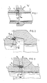
- the watertight seal 1 of figure 1 is arranged between adjoining prefabricated culvert elements, tunnel sections, sewer pipes or similar concrete elements 2.
- An elastic sealing strip 3 is arranged between a sealing surface 4 of a socket 5 of one concrete element 2 and a sealing surface 6 of a wedge 7 of the other concrete element 2 enveloped by the socket 5.
- One sealing surface 6 has a groove 8 retaining the elastic sealing strip 3 in an axial direction, whereas the other sealing surface 4 - viewed in the axial direction 9 from the bonded end 13 of the wedge 7 towards the free end 14 of said wedge - is converging.
- the profile of the sealing strip 3 (figure 2) has a ridge 10 directed towards the converging sealing surface 4 and adjoining a profile surface 11 diverging in the direction of convergence 9 of the converging sealing surface 4.
- Two channels 15 and 16 are recessed in the elastic material 12 of the elastic sealing strip 3, whilst the sealing strip 3 has a profile such that, when the two concrete elements 2 are slid towards one another, material 12 of the sealing strip shifts in the direction of convergence 9 of the converging sealing. surface 4 (see figure 3).
- the channel 15, which is located at a large distance from the groove edge 17 and which has an ample passage, is of great importance to the invention, because this channel 15 facilitates the aforesaid shift of the material 12 in the direction 9.
- the sealing strip 3 is rigid; at this place there is no channel or there is only one channel 16 having a narrow passage.
- the invention provides a sealing strip requiring a minimum amount of material 12 being on the one hand sufficiently rigid to avoid jamming between the groove edge 17 and the sealing surface 4 and nevertheless being on the other hand capable of bridging a large clearance space t in the zone (figure 5) having a large clearance space, since in the zone (figure 6) having minimum clearance space the groove edge 17 strikes the converging sealing surface 4.
- the axial boundary in the sliding interlock of the concrete elements 2 is formed by the contact of the material 12 with the inner front face 19 of the socket 5 (figures 6 and 9).
- the channels 15 and 16 are surrounded all around by elastic material 12 and are, therefore, closed so that the contents, for example, air, shifts from the narrow zone (figure 9) towards the wide zone (figure 8) where the sealing strip 3 is, so to say, slightly inflated. This applies to air filling and to a greater extent to fluid filling. As the case may be, the channels 15 and 16 may be filled with foam rubber.
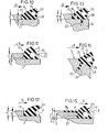
- the sealings strips 20 to 25 of figs. 10 to 15 operate in the same manner as the sealing strip 3, but they have a different transverse profile.
- the sealing strips 20, 21, 22 and 23 each have at the groove edge 17 a height q, which is smaller than the groove height r.
- the sealing strip 25 of figure 15 is integral with an elastic stop sleeve 26, so that the height v of the groove 8 is equal to the height of the slightly depressed stop sleeve 26 together with the height r of the concrete 27.
- the tendency to an axial shift direction 9 is furthered by a bevelled part 28.
- said shift is furthered by a thin kinked wall 29 between the front side 30 and the channel 15.
- the sealing strip 22 of figure 12 has a recessed channel 31 open to the front side. Nevertheless the sealing strip 22 has a rigidity such that it engages the sealing surface 4 with a vigorous contact pressure.
- the sealing strips 23 and 24 are embedded by means of an anchor ring 32 in the concrete 33 of the concrete element 2.
- the groove 34 is essentially formed by bevelling the free edge 35 of the wedge 7. Therefore, the wedge 7 may be short.
- Figure 15 shows that the sealing strip 25 is moulded together with the stop sleeve 26. In this case an elastic and at the same time rigid stop sleeve 26 disposed outside of the groove 8 is combined with a weak, flexible sealing strip 25 being thus capable of absorbing a large clearance variation.
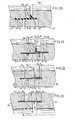
- An elastic sealing strip 43 is accommodated between a sealing surface 44 of a socket 45 of one concrete element 42 and a sealing surface 46 of an annular wedge 47 of the other concrete element 42 enveloped by the socket 45.
- each sealing surface 44 and 46 has a wedge-shaped groove 48 receiving the elastic sealing strip 43.
- the sealing strip 43 has a first anchor ring 49, which is accommodated in a watertight relationship in a groove 48 of one sealing surface 44, a second anchor ring 50 accommodated in a watertight relationship in a groove 51 of the other sealing surface 46 and a sleeve 52 arranged between the two anchor rings 49 and 50 and forming a closed unit therewith, said sheet allowing a relative axial displacement of the anchor rings 49 and 50 and hence of the concrete elements 42.
- Figures 18 and 19 show that the wedge-shaped groove 48, 51 provided in one concrete element 42 - viewed in an axial direction 54 - is located opposite anedge 55, 56 of the other concrete element 42, so that when the concrete elements 42 are joined, the anchor rings 49 and 50 are firmly and hence permanently pressed in a sealing relationship into the grooves 48, 51 along the pressure lines 57 and 58.
- the sleeve 52 is folded in the axial direction 54, that is to say, with an internal, annular fold 94 and an external fold 95, whilst the intermediate surface portion 59 constitutes a radial stop avoiding the impact of concrete on concrete.
- the folds 94 and 95 allow a large relative displacement and/or a large relative angular turn of the concrete elements 42, whilst the imperviousness to water is maintained.
- the elastic anchor ring 60 of the sealing strip 61 of figure 20 is embedded in the concrete 62 of one concrete element 42.
- the sealing strip 61 is identical to the sealing strip 43.
- the sealing strip 64 of the watertight seal 92 of figure 21 comprises two rings 65 and 66 interconnected through a watertight joint 67.
- the ring 65 of elastic material 68 comprises an anchor ring 69, for example of metal, embedded in the concrete 62 and a coupling ring 70 of hooklike section, around which a coupling ring 71 fits having a complementary sharkhead-like section in order to obtain a waterproof snap joint.
- the coupling ring 71 forms part of the elastic ring 66, which comprises apart from the coupling ring 71 in order of succession in conjunction herewith a folded sleeve 73, a stop sleeve 74, an impact ring 75 and an-anchor ring 76 embedded in the concrete 62.
- the coupling rings 70 and 71 can be forcibly pressed one into the other since the edge 55 of the wedge 47 is disposed axially opposite the joint 67.
- the impact ring 75 limits the axial telescopic movement.
- the watertight seal 91 of figures 22 and 23 comprises a sealing strip 77 also consisting of two rings 78 and 79 interconnected by means of a sliding joint 80.
- One ring 79 is embedded as an anchor ring in the concrete 62 of one concrete element 81, it has a U-shaped profile and it is elastic.
- the other ring 78 of metal or a different, rigid material has an anchor ring 82 embedded in the concrete 62 of the other concrete element 81 and extends in the form of an axially extending cylinder 83 along the outer periphery of the wedge in watertight relationship into the ring 79.
- axial shift of the concrete elements 81 the ring 83 can slide in the ring 79, whilst the impermeability to water is maintained.
- the sealing strip 93 of the watertight seal 90 of figure 24 comprises, apart from the two anchor rings 84 and 85 embedded in the concrete 62 and each being provided with a coupling ring 86 of hook-like section, an annular sleeve 87 arranged between the former.
- the annular sheet comprises two coupling rings 89 of sharkhead-like section arranged one on each side of a fold 88. This annular sheet 87 may, if desired, be put in place afterwards, for example, from the inner side, when the pipe to be laid is accessible from the inner side.
Abstract
A watertight seal between two adjoining channel- shaped concrete elements (2) has an elastic sealing strip (3) sandwiched between a socket (5) of one concrete element (2) and a wedge (4) of the other concrete element (2) enveloped by the socket (5). The sealing strip (3) is recessed and has a transverse profile such, that when the socket (5) is slid over the wedge (4), material (12) of the sealing strip (3) shifts in a direction contrary to movement of the socket (5) in order to prevent damage of the sealing strip (3).
Description
- Water tight seal between two concrete elements.
- The invention relates to a watertight seal between two adjoining, prefabricated culvert elements, tunnel sections, sewer pipes or similar concrete elements, in which an elastic sealing strip is sandwiched between a sealing surface of a socket of one concrete element and a sealing surface of a wedge of the other concrete element enveloped by the socket, in which one sealing surface has a groove retaining the elastic sealing strip in an axial direction and the other sealing surface - viewed in the direction from the bonded end of the wedge towards the free end of the wedge - is converging and in which the profile of the sealing strip, in the unstressed state, has a ridge directed towards the converging sealing surface and adjoining a profile face diverging in the direction of convergence of the converging sealing surface.
- Such a seal is known from GB - A - PS 464,087. When the concrete elements are slid to one another the material of the sealing strip may be jammed between the edge of the groove and the opposite surface, so that the sealing strip may be damaged and/or the socket may break down due to excessive radial stress.
- Moreover, in the case of large tolerance of the sealing surfaces the watertightness is not ensured, because the radial contact pressure of the sealing strip on the sealing surfaces is highly dependent on the degree of flattening of the sealing strip, which varies with the noncircu- larity, the accuracy of dimensions and aligning defects. The aligning defects are involved in mounting operations and/or subsidence of the subsoil supporting the concrete elements.
- The invention has for its object to improve the watertight seal of the kind set forth in the preamble. To this end at least one channel is made in the elastic material of the sealing strip, whilst the sealing strip has a transverse profile, such that, when the two conorete elements are joined, material of the sealing strip shifts in a converging direction of the converging sealing surface.
- In this way it is avoided that material becomes jammed between the edge of the groove and the opposite sealing surface, since the shifting material moves away from said edge. Furthermore, the material of the sealing strip pushed towards a free space remains available as undamaged spare material for expanding, if necessary, in a radial sense and for nestling with adequate contact pressure against the opposite sealing surface to guarantee a watertight seal.
- When the channel is filled with fluid and when the wedge and the socket are asymmetrically disposed, this fluid tends to shift in a tangential direction from a narrow towards the wide zone of the sealing gap. Thus in the area of the narrow zone the material of the sealing strip can more readily shift towards the free space, whereas in the area of the wide zone the sealing strip is, so to say, additionally pumped with a hardly compressible fluid. If the channel is bounded on all sides by elastic material of the sealing strip and is filled with air, this technical effect is also produced, be it to a lesser extent.
- In an asymmetrical sealing strip the channel is preferably located on the side of the sealing strip remote from the groove edge.
- If the sealing strip also has a stop sleeve disposed outside of the groove, this stop sleeve operates as a bed absorbing the high forces with which the concrete elements bear one on the other. Thus the seal is relieved of these high bearing forces, so that in the area of the sealing surfaces the sealing strip can be flexible and deformable over a large radial distance.
- The invention furthermore improves a watertight seal between two adjoining, prefabricated culvert elements, tunnel sections or suchlike concrete elements, in which an elastic sealing strip is sandwiched between a sealing surface of a socket of one concrete element and a sealing surface of a wedge of the other concrete element enveloped by the socket, at least one sealing surface having a groove accommodating the elastic sealing strip, so that particularly in the event of appreciable and/or frequent relative axial displacements of the concrete elements the watertightness remains guaranteed. According to the invention this is achieved by providing the sealing strip with a first anchor ring ring accommodated in a watertight relationship in a groove of one sealing surface, with a second anchor ring held in watertight relationship in a groove of the other sealing surface and with a sleeve arranged between the two anchor rings and allowing a relative, axial displacement of the anchor rings. In this case each anchor ring ensures the watertightness with respect to the associated concrete element, whilst the sleeve bridges in a watertight manner the axial distance between the anchor rings irrespective of changes of said distance.
- When the sleeve is folded in an axial direction, a large axial displacement between the concrete elements is allowed.
- When one of the grooves is wedge-shaped in an axial direction, the anchor ring can be readily arranged in sealing relationship with the groove, particularly so when the wedge-shaped groove of one concrete element - viewed in an axial direction - is disposed opposite an edge of the other concrete element.
- In a further variant the watertightness can be readily obtained in the area of the anchor ring by embedding at least one of the two anchor rings in the concrete of the associated element during its manufacture.
- Mounting a pipe of concrete_elements with watertight seals according to the invention is facilitated by shaping the sealing strip in the form of at least two rings connected with one another by a watertight coupling. This coupling may be a snap joint or a slide joint.
- When the sealing strip consists of three rings coupled by watertight joints i.e. a first anchor ring, a second anchor ring and an intermediate sleeve ring, the sleeve may even be arranged in place after the concrete elements are put in their places.
- The invention will be described more fully hereinafter with reference to a drawing.
- The drawing shows in:
- figures 1, 4 and 7 longitudinal sectional views of a watertight seal in accordance with the invention between two concrete elements disposed in respectively different positions,
- figure 2 detail II of figure 1 on an enlarged scale during the mounting operation,
- figure 3 detail II of figure 1 on an enlarged scale in operational position,
- figure 5 detail V of figure 4 on an enlarged scale, figure 6 detail VI of figure 4 on an enlarged scale,
- figure 8 detail VIII of figure 7 on an enlarged scale,
- figure 9 detail IX of figure 7 on an enlarged scale,
- figures 10 to 15 respectively different sealing strips arranged in a groove for obtaining a watertight seal in accordance with the invention,
- figures 16 and 17 longitudinal sectional views of a further watertight seal in accordance with the invention arranged between two concrete elements in respectively different positions,
- figures 18 and 19 details XVIII and XIX respectively of figure 17,
- figures 20, 21, 22, and 24 sectional views like figure 19 of respectively different watertight seals in accordance with the invention, and
- figure 23 a sectional view corresponding to figure 18 of a watertight seal shown in figure 22.
- The watertight seal 1 of figure 1 is arranged between adjoining prefabricated culvert elements, tunnel sections, sewer pipes or
similar concrete elements 2. Anelastic sealing strip 3 is arranged between a sealingsurface 4 of asocket 5 of oneconcrete element 2 and a sealingsurface 6 of awedge 7 of theother concrete element 2 enveloped by thesocket 5. Onesealing surface 6 has agroove 8 retaining theelastic sealing strip 3 in an axial direction, whereas the other sealing surface 4 - viewed in theaxial direction 9 from thebonded end 13 of thewedge 7 towards thefree end 14 of said wedge - is converging. In the unstressed state the profile of the sealing strip 3 (figure 2) has aridge 10 directed towards the convergingsealing surface 4 and adjoining aprofile surface 11 diverging in the direction ofconvergence 9 of the convergingsealing surface 4. Twochannels elastic material 12 of theelastic sealing strip 3, whilst thesealing strip 3 has a profile such that, when the twoconcrete elements 2 are slid towards one another,material 12 of the sealing strip shifts in the direction ofconvergence 9 of the converging sealing. surface 4 (see figure 3). Thechannel 15, which is located at a large distance from thegroove edge 17 and which has an ample passage, is of great importance to the invention, because thischannel 15 facilitates the aforesaid shift of thematerial 12 in thedirection 9. Near theedge 17 of the groove thesealing strip 3 is rigid; at this place there is no channel or there is only onechannel 16 having a narrow passage. - The invention provides a sealing strip requiring a minimum amount of
material 12 being on the one hand sufficiently rigid to avoid jamming between thegroove edge 17 and the sealingsurface 4 and nevertheless being on the other hand capable of bridging a large clearance space t in the zone (figure 5) having a large clearance space, since in the zone (figure 6) having minimum clearance space thegroove edge 17 strikes the convergingsealing surface 4. This occurs in the case of non-circularity of thesocket 5 and/or thewedge 7 and/or in the case of an eccentric interengagement (figures 5 and 6) and/or by an interengagement by an angular turn (figures 7 to 9). The axial boundary in the sliding interlock of theconcrete elements 2 is formed by the contact of thematerial 12 with theinner front face 19 of the socket 5 (figures 6 and 9). - The
channels elastic material 12 and are, therefore, closed so that the contents, for example, air, shifts from the narrow zone (figure 9) towards the wide zone (figure 8) where thesealing strip 3 is, so to say, slightly inflated. This applies to air filling and to a greater extent to fluid filling. As the case may be, thechannels - The sealings strips 20 to 25 of figs. 10 to 15 operate in the same manner as the
sealing strip 3, but they have a different transverse profile. Thesealing strips - The
sealing strip 25 of figure 15 is integral with anelastic stop sleeve 26, so that the height v of thegroove 8 is equal to the height of the slightlydepressed stop sleeve 26 together with the height r of theconcrete 27. As illustrated in figures 10, 13 and 14 the tendency to anaxial shift direction 9 is furthered by abevelled part 28. As shown in figure 11, said shift is furthered by a thin kinkedwall 29 between thefront side 30 and thechannel 15. Thesealing strip 22 of figure 12 has arecessed channel 31 open to the front side. Nevertheless thesealing strip 22 has a rigidity such that it engages the sealingsurface 4 with a vigorous contact pressure. - The
sealing strips 23 and 24 (figures 13 and 14) are embedded by means of ananchor ring 32 in theconcrete 33 of theconcrete element 2. As shown in figure 14, thegroove 34 is essentially formed by bevelling the free edge 35 of thewedge 7. Therefore, thewedge 7 may be short. Figure 15 shows that thesealing strip 25 is moulded together with thestop sleeve 26. In this case an elastic and at the same timerigid stop sleeve 26 disposed outside of thegroove 8 is combined with a weak,flexible sealing strip 25 being thus capable of absorbing a large clearance variation. - The
waterproof seal 41 of figures 16 to 19, like thewaterproof seals prefabicated concrete elements 42. Anelastic sealing strip 43 is accommodated between a sealing surface 44 of a socket 45 of oneconcrete element 42 and a sealing surface 46 of anannular wedge 47 of the otherconcrete element 42 enveloped by the socket 45. In figures 16 to 19 each sealing surface 44 and 46 has a wedge-shapedgroove 48 receiving theelastic sealing strip 43. The sealingstrip 43 has afirst anchor ring 49, which is accommodated in a watertight relationship in agroove 48 of one sealing surface 44, asecond anchor ring 50 accommodated in a watertight relationship in agroove 51 of the other sealing surface 46 and asleeve 52 arranged between the two anchor rings 49 and 50 and forming a closed unit therewith, said sheet allowing a relative axial displacement of the anchor rings 49 and 50 and hence of theconcrete elements 42. - Figures 18 and 19 show that the wedge-shaped
groove anedge concrete element 42, so that when theconcrete elements 42 are joined, the anchor rings 49 and 50 are firmly and hence permanently pressed in a sealing relationship into thegrooves sleeve 52 is folded in theaxial direction 54, that is to say, with an internal,annular fold 94 and anexternal fold 95, whilst theintermediate surface portion 59 constitutes a radial stop avoiding the impact of concrete on concrete. Thefolds concrete elements 42, whilst the imperviousness to water is maintained. - The
elastic anchor ring 60 of the sealingstrip 61 of figure 20 is embedded in the concrete 62 of oneconcrete element 42. In the otherconcrete element 42 the sealingstrip 61 is identical to the sealingstrip 43. - The sealing strip 64 of the
watertight seal 92 of figure 21 comprises tworings 65 and 66 interconnected through a watertight joint 67. Thering 65 of elastic material 68 comprises an anchor ring 69, for example of metal, embedded in the concrete 62 and a coupling ring 70 of hooklike section, around which acoupling ring 71 fits having a complementary sharkhead-like section in order to obtain a waterproof snap joint. Thecoupling ring 71 forms part of the elastic ring 66, which comprises apart from thecoupling ring 71 in order of succession in conjunction herewith a folded sleeve 73, astop sleeve 74, animpact ring 75 and an-anchor ring 76 embedded in the concrete 62. The coupling rings 70 and 71 can be forcibly pressed one into the other since theedge 55 of thewedge 47 is disposed axially opposite the joint 67. Theimpact ring 75 limits the axial telescopic movement. - The
watertight seal 91 of figures 22 and 23 comprises a sealingstrip 77 also consisting of tworings 78 and 79 interconnected by means of a sliding joint 80. One ring 79 is embedded as an anchor ring in the concrete 62 of oneconcrete element 81, it has a U-shaped profile and it is elastic. Theother ring 78 of metal or a different, rigid material has ananchor ring 82 embedded in the concrete 62 of the otherconcrete element 81 and extends in the form of an axially extending cylinder 83 along the outer periphery of the wedge in watertight relationship into the ring 79. In the event of a relative angular turn and/or a relative, axial shift of theconcrete elements 81 the ring 83 can slide in the ring 79, whilst the impermeability to water is maintained. - The sealing
strip 93 of thewatertight seal 90 of figure 24 comprises, apart from the two anchor rings 84 and 85 embedded in the concrete 62 and each being provided with acoupling ring 86 of hook-like section, anannular sleeve 87 arranged between the former. The annular sheet comprises two coupling rings 89 of sharkhead-like section arranged one on each side of afold 88. Thisannular sheet 87 may, if desired, be put in place afterwards, for example, from the inner side, when the pipe to be laid is accessible from the inner side.
Claims (26)
1. A watertight seal (1) between two adjoining, prefabricated culvert elements, tunnel sections, sewer pipes or similar concrete elements (2), in which an elastic sealing strip (3) is sandwiched between a sealing surface (4) of a socket (5) of one concrete element (2) and a sealing surface (6) of a wedge (7) of the other concrete element (2) enveloped by the socket (5), one sealing surface (6) having a groove (8) retaining the elastic sealing strip (3) in an axial direction and the other sealing surface (4) - viewed in the direction from the bonded end (13) of the wedge (7) towards the free end (14) of the wedge (7) - being converging and in which the profile of the sealing strip (3), in the unstressed state, has a ridge (10) directed towards the converging sealing surface (4) and joining a profile face (11) diverging in the direction of convergence (9) of the converging sealing surface (4), characterized in that in the elastic material (12) of the sealing strip (3) at least one channel (15) is recessed and the sealing strip (3) has a transverse profile, such that when the two concrete elements (2) are slid one into the other, material (12) of the sealing strip (3) shifts in the direction of convergence (9) of the converging sealing surface (4).
2. A watertight seal as claimed in claim 1, characterized in that the channel (15, 16) is bounded on all sides by elastic material (12) of the sealing strip (3).
3. A watertight seal as claimed in claim 1 or 2, characterized in that the channel (15, 16) is filled with fluid.
4. A watertight seal as claimed in claim 1, 2 or 3, characterized in that with respect to a medium plane at right angles to the axis of the wedge, the sealing strip (3) is asymmetrical and in that at least a voluminous channel is located on the side remote from the groove edge (17).
5. A watertight seal as claimed in any one of the preceding claims, characterized in that the sealing strip (25) has, in addition, a stop sleeve (26) disposed outside of the groove (8).
6. A watertight seal (41) between two adjoining, prefabricated culvert elements, tunnel sections or similar concrete elements (42), in which an elastic sealing strip (43) is sandwiched between a sealing surface (44) of a socket (45) of one concrete element (42) and a sealing surface (46) of a wedge (47) of the other concrete element (42) enveloped by the socket (45), at least one sealing surface (46) having a groove (48) receiving the elastic sealing strip (43), characterized in that the sealing strip (43) comprises a first anchor ring (49) accommodated in a watertight relationship in a groove (48) of one sealing surface (44), a second anchor ring (50) accommodated in watertight relationship in a groove (51) of the other sealing surface (46) and a sleeve (52) between the two anchor rings (49 and 50) and allowing a relative axial displacement of the anchor rings (49 and 50).
7. A watertight seal as claimed in claim 6, characterized in that the sheet (52) is folded in an axial direction.
8. A watertight seal as claimed in claim 6 or 7, characterized in that at least one of the grooves (48, 51) is wedge-shaped in an axial direction.
9. A watertight seal as claimed in claim 6, 7 or 8, characterized in that the wedge-shaped groove (48) recessed in one concrete element (42) - viewed in the axial direction (54) - is disposed opposite an edge (55) of the other concrete element (42).
10. A watertight seal as claimed in any one of claims 5 to 9, characterized in that at least one (60) of the two anchor rings (60, 49) is embedded in the concrete (62) during the manufacture of the associated concrete element (42).
11. A watertight seal as claimed in any one of claims 6 to 10, characterized in that the sealing strip (64) comprises at least two rings (65 and 66) interconnected through a watertight joint (67).
12. A watertight seal as claimed in claim 11, characterized in that the joint (67) is a snap joint.
13. A watertight seal as claimed in claim 11, characterized in that the joint is a sliding joint (80).
14. A watertight seal as claimed in claim 11 or 12, characterized in that the sealing strip (93) comprises three rings (84, 85, 87) interconnected by watertight joints i.e. a first anchor ring (84), a second anchor ring (85) and an annular sheet (87) arranged between the former.
1. A watertight seal (1) between two adjoining, prefabricated culvert elements, tunnel sections, sewer pipes or similar concrete elements (2), in which an elastic sealing strip (3) is sandwiched between a sealing surface (4) of a socket (5) of one concrete element (2) and a sealing surface (6) of a wedge (7) of the other concrete element (2) enveloped by the socket (5), one sealing surface (6) having a groove (8) retaining the elastic sealing strip (3) in an axial direction and the other sealing surface (4) - viewed in the direction from the bonded end (13) of the wedge (7) towards the free end (14) of the wedge (7) - being converging and in which the profile of the sealing strip (3), in the unstressed state, has a ridge (10) directed towards the converging sealing surface (4), at least one channel (15) being recessed in the elastic material (12) of the sealing strip (3), characterized in that the sealing strip (3) has a transverse profile, such that when the two concrete elements (2) are slid one into the other, material (12) of the sealing strip (3) shifts in the direction of convergence (9) of the converging sealing surface (4) beyond the free end of the wedge.
2. A watertight seal as claimed in claim 1, characterized in that the channel (15, 16) is bounded on all sides by elastic material (12) of the sealing strip (3).
3. A watertight seal as claimed in claim 1 or 2, characterized in that the channel (15, 16) is filled with fluid.
4. A watertight seal as claimed in claim 1, 2 or 3, characterized in that with respect to a medium plane at right angles to the axis of the wedge, the sealing strip (3) is asymmetrical and in that at least a voluminous channel is located on the side remote from the groove edge (17).
5. A watertight seal as claimed in any one of the preceding claims, characterized in that the sealing strip (25) has, in addition, a stop sleeve (26) disposed outside of the groove (8).
6. A watertight seal (41) between two adjoining, prefabricated culvert elements, tunnel sections or similar concrete elements (42), in which an elastic sealing strip (43) is sandwiched between a sealing surface (44) of a socket (45) of one concrete element (42) and a sealing surface (46) of a wedge (47) of the other concrete element (42) enveloped by the socket (45), at least one sealing surface (46) having a groove (48) receiving the elastic sealing strip (43), characterized in that the sealing strip (43) comprises a first anchor ring (49) accommodated in a watertight relationship in a groove (4S) of one sealing surface (44), a second anchor ring (50) accommodated in watertight relationship in a groove (51) of the other sealing surface (46) and a sleeve (52) between the two anchor rings (49 and 50) and allowing a relative axial displacement of the anchor rings (49 and 50), due to being folded in axial direction.
7. A watertight seal as claimed in claim 6, characterized in that at least one of the grooves (48, 51) is wedge-shaped in axial direction.
8. A watertight seal as claimed in claim 6 or 7, characterized in that the wedge-shaped groove (48) recessed in one concrete element (42) - viewed in the axial direction (54) - is disposed opposite an edge (55) of the other concrete element (42).
9. A watertight seal as claimed in any one of claims 6 to 8, characterized in that at least one (60) of the two anchor rings (60, 49) is embedded in the concrete (62) during the manufacture of the associated concrete element (42).
10. A watertight seal as claimed in any one of claims 6 to 8, characterized in that the sealing strip (64) comprises at least two rings (65 and 66) interconnected through a watertight joint (67).
11. A watertight seal as claimed in claim 10, characterized in that the joint (67) is a snap joint.
12. A watertight seal as claimed in claim 11, characterized in that the sealing strip (93) comprises three rings (84, 85, 87) interconnected by watertight joints i.e. a first anchor ring (84), a second anchor ring (85) and an annular sheet (87) arranged between the former.
Priority Applications (2)
| Application Number | Priority Date | Filing Date | Title |
|---|---|---|---|
| EP81200017A EP0056169A1 (en) | 1981-01-08 | 1981-01-08 | Water tight seal between two concrete elements |
| US06/322,178 US4449720A (en) | 1981-01-08 | 1981-11-17 | Watertight seal between two concrete elements |
Applications Claiming Priority (1)
| Application Number | Priority Date | Filing Date | Title |
|---|---|---|---|
| EP81200017A EP0056169A1 (en) | 1981-01-08 | 1981-01-08 | Water tight seal between two concrete elements |
Publications (1)
| Publication Number | Publication Date |
|---|---|
| EP0056169A1 true EP0056169A1 (en) | 1982-07-21 |
Family
ID=8188100
Family Applications (1)
| Application Number | Title | Priority Date | Filing Date |
|---|---|---|---|
| EP81200017A Ceased EP0056169A1 (en) | 1981-01-08 | 1981-01-08 | Water tight seal between two concrete elements |
Country Status (2)
| Country | Link |
|---|---|
| US (1) | US4449720A (en) |
| EP (1) | EP0056169A1 (en) |
Families Citing this family (5)
| Publication number | Priority date | Publication date | Assignee | Title |
|---|---|---|---|---|
| US4961599A (en) * | 1988-08-09 | 1990-10-09 | Delery Jr Oliver S | Sealing gland construction for use in hydraulic unit joints |
| US20060186662A1 (en) * | 2005-02-23 | 2006-08-24 | Vertex, Inc. | Cast-in-place gasket for pipe joints |
| US7922179B2 (en) * | 2006-02-21 | 2011-04-12 | Vertex, Inc. | Cast-in-place gasket for pipe joints |
| US8794639B2 (en) * | 2008-12-16 | 2014-08-05 | A-Lok Products, Inc. | Sealing assembly having liquid-filled seal |
| US20120025471A1 (en) * | 2008-12-16 | 2012-02-02 | Vertex, Inc. | Self adjusting gasket for pipe joints |
Citations (13)
| Publication number | Priority date | Publication date | Assignee | Title |
|---|---|---|---|---|
| US1345829A (en) * | 1919-07-23 | 1920-07-06 | Albert J Boyle | Joint for concrete pipe |
| US1530105A (en) * | 1923-07-07 | 1925-03-17 | Lawrence E Bufton | Expansion joint |
| DE557533C (en) * | 1931-03-11 | 1932-08-24 | J H Gustav Burmeister Fa | Gas and watertight connection of pipes and fittings |
| US1916479A (en) * | 1932-06-28 | 1933-07-04 | Howell Bruce Gordon | Pipe coupling |
| GB464087A (en) * | 1936-10-27 | 1937-04-12 | Gwynne Burnell Brader | Improvements in or relating to pipe joints |
| US2477533A (en) * | 1946-10-19 | 1949-07-26 | William A Whiting | Pipe joint |
| DE1750648U (en) * | 1957-05-21 | 1957-08-14 | Ed Zueblin A G | ARRANGEMENT FOR JOINT SEALING FOR PIPES MADE OF PREFABRICATED CONCRETE, REINFORCED CONCRETE OR SIMILAR PIPES. |
| US3046028A (en) * | 1959-12-01 | 1962-07-24 | Hamilton Kent Mfg Company | Gasket and use thereof |
| US3173699A (en) * | 1962-08-24 | 1965-03-16 | Hamilton Kent Mfg Co | Annular gasket |
| US3575430A (en) * | 1969-01-10 | 1971-04-20 | Certain Teed Prod Corp | Pipe joint packing ring having means limiting assembly movement |
| CH514092A (en) * | 1969-10-10 | 1971-10-15 | Huesler Anton | Pipe connections between two concrete pipes |
| FR2158977A5 (en) * | 1971-10-25 | 1973-06-15 | Forsheda Ideutveckling Ab | |
| DE7736620U1 (en) * | 1978-05-03 | Albert Steinhoff, Herstellung Und Handel Von Und Mit Gummiwaren, 4405 Nottuln | Sealing profile made of elastically deformable material |
Family Cites Families (3)
| Publication number | Priority date | Publication date | Assignee | Title |
|---|---|---|---|---|
| CA682728A (en) * | 1964-03-24 | J. Mccance Edgar | Pipe connecting assembly and gasket therefor | |
| US3015510A (en) * | 1956-12-12 | 1962-01-02 | Kenton Schuyler Bates | Pipe sealing gasket |
| FR1479549A (en) * | 1966-03-25 | 1967-05-05 | Ct De Rech S Ed Pont A Mousson | Gasket for pipe joints and gasket with application |
-
1981
- 1981-01-08 EP EP81200017A patent/EP0056169A1/en not_active Ceased
- 1981-11-17 US US06/322,178 patent/US4449720A/en not_active Expired - Fee Related
Patent Citations (14)
| Publication number | Priority date | Publication date | Assignee | Title |
|---|---|---|---|---|
| DE7736620U1 (en) * | 1978-05-03 | Albert Steinhoff, Herstellung Und Handel Von Und Mit Gummiwaren, 4405 Nottuln | Sealing profile made of elastically deformable material | |
| US1345829A (en) * | 1919-07-23 | 1920-07-06 | Albert J Boyle | Joint for concrete pipe |
| US1530105A (en) * | 1923-07-07 | 1925-03-17 | Lawrence E Bufton | Expansion joint |
| DE557533C (en) * | 1931-03-11 | 1932-08-24 | J H Gustav Burmeister Fa | Gas and watertight connection of pipes and fittings |
| US1916479A (en) * | 1932-06-28 | 1933-07-04 | Howell Bruce Gordon | Pipe coupling |
| GB464087A (en) * | 1936-10-27 | 1937-04-12 | Gwynne Burnell Brader | Improvements in or relating to pipe joints |
| US2477533A (en) * | 1946-10-19 | 1949-07-26 | William A Whiting | Pipe joint |
| DE1750648U (en) * | 1957-05-21 | 1957-08-14 | Ed Zueblin A G | ARRANGEMENT FOR JOINT SEALING FOR PIPES MADE OF PREFABRICATED CONCRETE, REINFORCED CONCRETE OR SIMILAR PIPES. |
| US3046028A (en) * | 1959-12-01 | 1962-07-24 | Hamilton Kent Mfg Company | Gasket and use thereof |
| US3173699A (en) * | 1962-08-24 | 1965-03-16 | Hamilton Kent Mfg Co | Annular gasket |
| US3575430A (en) * | 1969-01-10 | 1971-04-20 | Certain Teed Prod Corp | Pipe joint packing ring having means limiting assembly movement |
| CH514092A (en) * | 1969-10-10 | 1971-10-15 | Huesler Anton | Pipe connections between two concrete pipes |
| FR2158977A5 (en) * | 1971-10-25 | 1973-06-15 | Forsheda Ideutveckling Ab | |
| GB1409072A (en) * | 1971-10-25 | 1975-10-08 | Forsheda Ideutveckling Ab | Manufacturing a pipe secrion having a sealing ring |
Also Published As
| Publication number | Publication date |
|---|---|
| US4449720A (en) | 1984-05-22 |
Similar Documents
| Publication | Publication Date | Title |
|---|---|---|
| US4303103A (en) | Internal sleeve seal and method of use | |
| EP0543103B1 (en) | A sealing device | |
| US5772253A (en) | Pipe repair or jointing collar | |
| CA2674122C (en) | Method of forming and maintaining a concrete structure | |
| JPH10131319A (en) | Cut-off joint member of concrete joining object | |
| JPH11501091A (en) | Sealed joint and its manufacturing method | |
| US4241762A (en) | Composite underground fluid conduit of concrete and steel sections | |
| GB2218166A (en) | Jacking pipe seals | |
| EP0568302B1 (en) | Method of connecting two construction elements by using a deformable joint | |
| EP0056169A1 (en) | Water tight seal between two concrete elements | |
| FI67939C (en) | PACKNING AV GUMMI ELLER LIKNANDE MATERIAL | |
| US20150192014A1 (en) | Tunnel segment cross gasket | |
| US5165822A (en) | Pipe joint for driving pipes laid underground by the driving technique | |
| AU6142390A (en) | A seal ring for a sleeve joint | |
| GB2075086A (en) | Duct linings | |
| RU2117848C1 (en) | Inserted socket joint | |
| GB2217418A (en) | A conduit section with plastics coupling rings | |
| US5921716A (en) | Apparatus and method for forming a barrier wall | |
| CN113833924A (en) | Double water seal expansion joint | |
| US4060993A (en) | Water seal packing for sealing water at the coupling portion of underwater structures | |
| GB2186656A (en) | Improved sewer or tunnel lining | |
| JP2767209B2 (en) | Flexible segment for shield method | |
| GB2042118A (en) | Pipe coupling | |
| EP0244877B2 (en) | Joint sealing member | |
| GB2188997A (en) | Protecting pipe joints |
Legal Events
| Date | Code | Title | Description |
|---|---|---|---|
| PUAI | Public reference made under article 153(3) epc to a published international application that has entered the european phase |
Free format text: ORIGINAL CODE: 0009012 |
|
| 17P | Request for examination filed |
Effective date: 19811106 |
|
| AK | Designated contracting states |
Designated state(s): AT BE CH DE FR GB IT LU NL SE |
|
| STAA | Information on the status of an ep patent application or granted ep patent |
Free format text: STATUS: THE APPLICATION HAS BEEN REFUSED |
|
| 18R | Application refused |
Effective date: 19840514 |
|
| RIN1 | Information on inventor provided before grant (corrected) |
Inventor name: WOLTERS, TJAKO AALDRIK Inventor name: ROGGEKAMP, ALOYSIUS GERARDUS M. |