EP0056128A2 - Phase synchronizing circuit - Google Patents
Phase synchronizing circuit Download PDFInfo
- Publication number
- EP0056128A2 EP0056128A2 EP81110507A EP81110507A EP0056128A2 EP 0056128 A2 EP0056128 A2 EP 0056128A2 EP 81110507 A EP81110507 A EP 81110507A EP 81110507 A EP81110507 A EP 81110507A EP 0056128 A2 EP0056128 A2 EP 0056128A2
- Authority
- EP
- European Patent Office
- Prior art keywords
- phase
- frequency
- output
- circuit
- signal
- Prior art date
- Legal status (The legal status is an assumption and is not a legal conclusion. Google has not performed a legal analysis and makes no representation as to the accuracy of the status listed.)
- Granted
Links
Images


Classifications
-
- H—ELECTRICITY
- H03—ELECTRONIC CIRCUITRY
- H03L—AUTOMATIC CONTROL, STARTING, SYNCHRONISATION, OR STABILISATION OF GENERATORS OF ELECTRONIC OSCILLATIONS OR PULSES
- H03L7/00—Automatic control of frequency or phase; Synchronisation
- H03L7/06—Automatic control of frequency or phase; Synchronisation using a reference signal applied to a frequency- or phase-locked loop
- H03L7/16—Indirect frequency synthesis, i.e. generating a desired one of a number of predetermined frequencies using a frequency- or phase-locked loop
- H03L7/18—Indirect frequency synthesis, i.e. generating a desired one of a number of predetermined frequencies using a frequency- or phase-locked loop using a frequency divider or counter in the loop
- H03L7/197—Indirect frequency synthesis, i.e. generating a desired one of a number of predetermined frequencies using a frequency- or phase-locked loop using a frequency divider or counter in the loop a time difference being used for locking the loop, the counter counting between numbers which are variable in time or the frequency divider dividing by a factor variable in time, e.g. for obtaining fractional frequency division
- H03L7/1974—Indirect frequency synthesis, i.e. generating a desired one of a number of predetermined frequencies using a frequency- or phase-locked loop using a frequency divider or counter in the loop a time difference being used for locking the loop, the counter counting between numbers which are variable in time or the frequency divider dividing by a factor variable in time, e.g. for obtaining fractional frequency division for fractional frequency division
-
- H—ELECTRICITY
- H03—ELECTRONIC CIRCUITRY
- H03L—AUTOMATIC CONTROL, STARTING, SYNCHRONISATION, OR STABILISATION OF GENERATORS OF ELECTRONIC OSCILLATIONS OR PULSES
- H03L7/00—Automatic control of frequency or phase; Synchronisation
- H03L7/06—Automatic control of frequency or phase; Synchronisation using a reference signal applied to a frequency- or phase-locked loop
- H03L7/08—Details of the phase-locked loop
- H03L7/085—Details of the phase-locked loop concerning mainly the frequency- or phase-detection arrangement including the filtering or amplification of its output signal
- H03L7/087—Details of the phase-locked loop concerning mainly the frequency- or phase-detection arrangement including the filtering or amplification of its output signal using at least two phase detectors or a frequency and phase detector in the loop
Definitions
- the present invention relates to a circuit for synchronizing clock signals and can be applied to a case where recording and reproducing sections are synchronized with each other when digital data are copied on another recording medium in a digital recording and reproducing device which is intended to record and reproduce digital data.
- the reproducing device which copies digital data has usually error correcting function, thus allowing error-corrected digital data to be copied on the new recording medium. Therefore, different from the copying of analog data, even an audio signal of low frequency can be restored without being influenced by the speed fluctuation, wow, flutter and the like of reproducing system.
- the object of the present invention is therefore to synchronize a first clock signal.employed in the transmitting section with a second clock signal employed in the receiving section.
- a phase synchronizing circuit is provided with a phase locked loop including a first phase comparison circuit, a voltage controlled oscillator (VCO) for receiving the output of the first phase comparison circuit to produce an oscillation output of a predetermined frequency, and first frequency dividing means having at least-a first frequency divider to divide the frequency of oscillation output of the VCO, wherein a predetermined input signal is supplied to the first phase comparison circuit for obtaining first and second clock signals whose phases are synchronized with each other, the phase synchronizing circuit further including second frequency dividing means for dividing the output frequency of the VCO; a second phase comparison circuit for receiving, as inputs, the first clock signal which is an output from a predetermined output terminal of the first frequency dividing means and the second clock signal which is an output from the second frequency dividing means, to compare phases of these first and second clock signals; and frequency dividing ratio controlling means for controlling the first frequency divider and the second phase comparison circuit in such a way that the frequency dividing ratio of the first divider is changed to one of three stages of
- numeral 1 represents digital data reproducing section and 2 digital data recording section for recording the digital data reproduced.
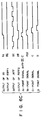
- Data reproducing and recording circuits in digital data reproducing and recording sections are omitted and only a phase synchronizing circuit for clock pulses employed in the data reproducing and recording sections is shown in Fig. 1.
- Numeral 11 denotes an input terminal to which reproduced signals from a digital data recording medium (not shown) are applied. Digitized audio and synchronizing signals, for example, are recorded on this recording medium. These synchronizing signals are separated from a reproduced TV format signal by a synchronizing signal separation circuit 12 to be supplied to a first phase comparison circuit 13. An output of the first phase comparison circuit 13 is fed back to the first phase comparison circuit 13. via a low pass filter 14, a voltage controlled oscillator (VCO), a first frequency divider circuit 16 whose frequency dividing ratio is 1/NA, a second frequency divider circuit 17 whose frequency dividing ratio is 1/NB, and a third frequency divider circuit 18 whose frequency dividing ratio is 1/NC.
- VCO voltage controlled oscillator
- the first phase comparison circuit 13, low pass filter 14, VCO 15, first, second and third frequency divider circuits form a phase locked loop (PLL).
- the VCO circuit 15 outputs an oscillation output or oscillation signal f s having a constant frequency.
- the recording section 2 are arranged a fourth frequency divider circuit 19 for dividing the oscillation signal f s of VCO 15 by NA, and a fifth frequency divider circuit 20 for dividing the output frequency of the divider circuit 19 by NB to produce a clock signal f a . It is assumed that the output of the second frequency divider circuit 17 is a first clock signal f a ' and that the output of fifth frequency divider circuit 20 is a second clock signal f a .
- a second phase comparison circuit 21 is arranged to compare the phase of first clock signal f a with that of second clock signal f a .
- Input terminals of a phase advancing circuit 22 and a phase lagging circuit 23 are connected to the output terminal of second frequency divider circuit 17, the phase advancing circuit 22 serving to produce an output signal f a ' + whose phase is advanced by a predetermined angle relative to the first clock signal f a ' and the phase lagging circuit 23 serving to produce an output signal f a ' - whose phase is lagged by same angle relative to the first clock signal f a '.
- Signals PH and PQ 2 obtained as comparison results are supplied from the comparison circuit 21 to the first frequency divider circuit 16.
- Levels of outputs PH and PQ 2 of second phase circuit 21 change according to the phase difference of first and second clock signals f a ' and f a , and the frequency dividing ratio of first divider circuit 16 changes according to the level change, thus allowing the phase of first clock signal to be accorded with that of second clock signal.
- the first frequency divider circuit 16, at first and then, the second phase comparison circuit 21 will be now described in detail referring to Fig. 2.
- the oscillation signal f s of VCO 15 is supplied to CK terminals of first, second, third and fourth shift registers SR1, SR2, SR3 and SR4.
- the arrangement of each of shift registers SR1, SR3 and SR4 is shown in Fig. 3.
- a QF terminal is arranged in the shift register SR2 to produce an output having a phase advanced only by half cycle of f s relative to the phase of an output on a terminal Q 2 .
- This frequency divider circuit 16 includes shift registers SRI - SR4, a JKFF (JK flip-flop) 24, AND gates 30, 31, NOR gates 32 - 36, and inverters 37, 38.
- the second phase comparison circuit 21 includes an AND gate 39, OR gates 40, 41, 42, NAND gates 43, 44, 45, NOR gates 46, 47, inverters 48, 49, and shift registers 25, 26.
- NAND gates 43 and 44 form a set-reset flip-flop RSFF 1 and NOR gates 46 and 47 a set-reset flip-flop RSFF 2 .
- To the OR gate 40 are supplied the output signal f a ' + of the phase advancing circuit 22, first clock signal f a ' and an inverted signal f a of second clock signal f a .
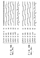
- first frequency divider circuit 16 shown in Fig. 2 Operation of first frequency divider circuit 16 shown in Fig. 2 will be now described referring to Figs. 4A-4C. It is assumed that the oscillation signal f s of VCO 15 shown in Fig. 1 has such a frequency as shown in Fig. 4A. It is also assumed that signals PH (output of RSFF l ) and PQ 2 (output of inverter 49) for controlling the frequency dividing ratio of first divider circuit 16 are of "L" level at the same time. Then, a J input terminal of JKFF 24 becomes “L” level and a K input terminal thereof "H” level. A first output terminal QC of JKFF 24-then becomes "H” level as shown in Fig. 4A.
- a second output terminal QC of JKFF 24 becomes "L" level.
- Levels of output voltages appearing at output terminals Q 1 - Q 4 of shift registers SR1 - SR4 change as shown in Fig. 4A, respectively.
- a clear signal is applied to a clear terminal CL of shift register SR1 through the inverter 38 and NOR gate 36. Therefore, the output signal f A of first frequency divider circuit 16 becomes a signal having a frequency in which the oscillation signal f s is divided to 1/7.
- Numerals 1/3 and 1/4 annexed to the signal waveform f A represent frequency dividing ratios, that is, time periods which are three and four times the cycle of signal f , respectively.
- the signal PQ 2 (output of inverter 49) becomes "H” level as shown in Fig. 4C.
- the signal PH output of RSFF 1
- J and K input terminals of JKFF 24 become “L” level, so that the JKFF 24 divides the output Q 2 to 1/2 at the time when it rises at the output terminal Q 2 of shift register SR2.
- the first frequency divider circuit 16 divides the signal f s to 1/7 when the first output terminal QC of JKFF 24 is of "H” level and to 1/8 when the first output terminal QC is of "L” level, as described referring to Fig. 4B.
- first and second clock signals f a ' and f a are detected and the frequency dividing ratio of first frequency divider circuit 16 is controlled according to the phase difference between these clock signals so as to synchronize phases of signals f a and f a ' immediately.
- the frequency dividing ratio of first frequency divider circuit 16 is usually 1/N
- the frequency dividing ratio of first frequency divider circuit 16 is controlled to 1/7 only one time during one cycle of first clock signal f a ' and then to 1/7.5 during the remaining period of one cycle.
- the frequency dividing ratio of first divider circuit 16 is controlled to 1/8 only one time and then to 1/7.5 during the remaining period of one cycle.
- phase advancing circuit 22 is intended to produce the signal f a ' + which corresponds to the output signal of second divider circuit 17 or first clock signal f a ' which has been advanced in phase only by half cycle of output pulse from the output terminal Q 2 of shift register SR2.
- the phase lagging circuit 23 is intended to produce the signal f a ' - corresponding to the first clock signal f a ' which has been lagged in phase only by half cycle of output pulse from the output terminal Q 2 .
- signals f a ' + and f a ' - are used in the second phase comparison circuit 21 to produce pulses of narrow width before and after the first clock signal f a ' rises.
- signals f a ' and f a ' - are used to obtain the output of AND gate 39, which receives, as inputs, f a ', f a ' - and f a (inverted signal of f a ), and the output of OR gate 40, which receives, as inputs, f a ' +' f a ' and f a .
- first frequency divider circuit can be operated so as to divide the frequency of the output signal f s of VCO 15 to 1/8. As the result, first and second clock signals f a ' and f a can be synchronized in phase.
- pulses of narrow width are generated through the OR gate 40- and AND gate 39 before and after the first clock signal f a ' rises, and the time when the second clock signal f a rises is detected by these pulses of narrow width. Even if noise is added to the second clock signal f a because of wiring arrangement, no influence is given to the synchronizing operation of first and second clock signals as long as noise is not added to the second clock signal f a during the period when pulses of narrow width are generated.
- the embodiment of the present invention shown in Fig. 1 is intended to separate vertical synchronizing signal from video signal, for example, by means of synchronizing signal separation circuit 12, and second, third and fifth frequency divider circuits 17, 18 and 20 are therefore arranged in addition to first and fourth divider circuits 16 and 19.
- second, third and fifth divider circuits may be omitted depending upon the frequency of input signal of first phase comparison circuit.
- the first frequency divider circuit 16 can be used as first frequency dividing means
- the fourth frequency divider circuit as second frequency dividing means. Therefore, the output of first frequency divider circuit 16 can be used as first clock signal and the output of fourth frequency divider circuit 19 as second clock signal.
- first and second clock signals f a ' and f a applicable only to reproducing and recording sections as in the case where digital data are reproduced and reproduced data are recorded on a new recording medium.
Abstract
Description
- The present invention relates to a circuit for synchronizing clock signals and can be applied to a case where recording and reproducing sections are synchronized with each other when digital data are copied on another recording medium in a digital recording and reproducing device which is intended to record and reproduce digital data.
- In the case of conventional analog tape recorders, for example, changes in the amplitude of signals such as audio signals which represent analog data are converted to those in the strength of magnetic field and the changes in the strength are recorded on a tape in the running direction thereof. Therefore, the performance of head, tape and the like gives influence to the dynamic range, distortion factor, and the like of the audio signals. Namely, the performance of tape running system gives influence to the frequency characteristics of the audio signals, wow, fluttering phenomenon, introduced noise and the like, and the audio signals are modulated by the fluctuation of tape speed and the like. Therefore, audio information analogically recorded is degraded in tone quality every time when it is copied.
- There has been developed these days a system which records audio signals as digital data and reproduces the recorded digital data. This system samples audio signals at a predetermined sampling frequency and quantizes the amplitude of sampled audio signals, thus recording audio signals as digital data on the tape, for example. Therefore, if it can be determined exactly that the logical level of information recorded on the tape is "0" or "1" when records on the tape are reproduced, analog waveforms before recorded will be restored completely. Generally, the recording medium on which digital data are recorded is sometimes deformed after it is used many times. In addition, error and the like are-sometimes caused on recorded contents. Accordingly, recorded contents must be sometimes copied on a new recording medium. The reproducing device which copies digital data has usually error correcting function, thus allowing error-corrected digital data to be copied on the new recording medium. Therefore, different from the copying of analog data, even an audio signal of low frequency can be restored without being influenced by the speed fluctuation, wow, flutter and the like of reproducing system.
- In the case of copying digital data on another recording medium, digital data are transferred between reproducing section and recording section. It is therefore necessary that the reproducing section is completely synchronized with the recording section. Namely, a clock signal employed in the reproducing section and a clock signal employed in the recording section must be synchronized in their phases.
- The object of the present invention is therefore to synchronize a first clock signal.employed in the transmitting section with a second clock signal employed in the receiving section.
- A phase synchronizing circuit according to the present invention is provided with a phase locked loop including a first phase comparison circuit, a voltage controlled oscillator (VCO) for receiving the output of the first phase comparison circuit to produce an oscillation output of a predetermined frequency, and first frequency dividing means having at least-a first frequency divider to divide the frequency of oscillation output of the VCO, wherein a predetermined input signal is supplied to the first phase comparison circuit for obtaining first and second clock signals whose phases are synchronized with each other, the phase synchronizing circuit further including second frequency dividing means for dividing the output frequency of the VCO; a second phase comparison circuit for receiving, as inputs, the first clock signal which is an output from a predetermined output terminal of the first frequency dividing means and the second clock signal which is an output from the second frequency dividing means, to compare phases of these first and second clock signals; and frequency dividing ratio controlling means for controlling the first frequency divider and the second phase comparison circuit in such a way that the frequency dividing ratio of the first divider is changed to one of three stages of 1/N, 1/(N+1), and 1/{[N+(N+1)]/2} (wherein N is a positive integer) according to the phase difference between the first and second clock signals so as to synchronize the phases of the first and second clock signals.
- This invention can be more fully understood from the following detailed description when taken in conjunction with the accompanying drawings, in which:
- Fig. 1 is a block diagram showing an embodiment of the present invention.
- Fig. 2 is a circuit diagram of'first frequency divider and second phase comparator shown in Fig. 1.
- Fig. 3 shows the internal arrangement of a.shift register SR1 shown in Fig. 2.
- Fig. 4A shows signal waveforms in the first frequency divider shown in Fig. 2 at the first frequency dividing mode of a first frequency divider circuit shown in Fig. 1.
- Fig. 4B shows signal waveforms in the first frequency divider shown in Fig. 2 at the second frequency dividing mode.
- Fig. 4C shows signal waveforms in the first frequency divider shown in Fig. 2 at the third frequency dividing mode.
- Fig. 5 is a chart for illustrating the phase difference between first and second clock signals shown in Fig. 1.
- Figs. 6A - 6C are timing charts to explain the operation of circuit shown in Fig. 2.
- In Fig. 1,
numeral 1 represents digital data reproducing section and 2 digital data recording section for recording the digital data reproduced. Data reproducing and recording circuits in digital data reproducing and recording sections are omitted and only a phase synchronizing circuit for clock pulses employed in the data reproducing and recording sections is shown in Fig. 1. - Numeral 11 denotes an input terminal to which reproduced signals from a digital data recording medium (not shown) are applied. Digitized audio and synchronizing signals, for example, are recorded on this recording medium. These synchronizing signals are separated from a reproduced TV format signal by a synchronizing
signal separation circuit 12 to be supplied to a firstphase comparison circuit 13. An output of the firstphase comparison circuit 13 is fed back to the firstphase comparison circuit 13. via alow pass filter 14, a voltage controlled oscillator (VCO), a firstfrequency divider circuit 16 whose frequency dividing ratio is 1/NA, a secondfrequency divider circuit 17 whose frequency dividing ratio is 1/NB, and a thirdfrequency divider circuit 18 whose frequency dividing ratio is 1/NC. The firstphase comparison circuit 13,low pass filter 14,VCO 15, first, second and third frequency divider circuits form a phase locked loop (PLL). TheVCO circuit 15 outputs an oscillation output or oscillation signal fs having a constant frequency. In therecording section 2, are arranged a fourthfrequency divider circuit 19 for dividing the oscillation signal fs ofVCO 15 by NA, and a fifthfrequency divider circuit 20 for dividing the output frequency of thedivider circuit 19 by NB to produce a clock signal fa. It is assumed that the output of the secondfrequency divider circuit 17 is a first clock signal fa' and that the output of fifthfrequency divider circuit 20 is a second clock signal fa. Clock signals for the reproducing circuit whose detail is not.shown are obtained through each of first, second and third frequency divider circuits and clock signals for the recording circuit which is not shown are obtained through each of fourth and fifth frequency divider circuits. A secondphase comparison circuit 21 is arranged to compare the phase of first clock signal f a with that of second clock signal fa. Input terminals of aphase advancing circuit 22 and aphase lagging circuit 23 are connected to the output terminal of secondfrequency divider circuit 17, thephase advancing circuit 22 serving to produce an output signal fa'+ whose phase is advanced by a predetermined angle relative to the first clock signal fa' and thephase lagging circuit 23 serving to produce an output signal fa'- whose phase is lagged by same angle relative to the first clock signal fa'. To the secondphase comparison circuit 21 are supplied the first clock signal fa', second clock signal fa , output fa'+ ofphase advancing circuit 22, output fa'- ofphase lagging circuit 23, and signals Qc and Qc from firstfrequency divider circuit 16 which will be described later. Signals PH and PQ2 obtained as comparison results are supplied from thecomparison circuit 21 to the firstfrequency divider circuit 16. Levels of outputs PH and PQ2 ofsecond phase circuit 21 change according to the phase difference of first and second clock signals fa ' and fa , and the frequency dividing ratio offirst divider circuit 16 changes according to the level change, thus allowing the phase of first clock signal to be accorded with that of second clock signal. The firstfrequency divider circuit 16, at first and then, the secondphase comparison circuit 21 will be now described in detail referring to Fig. 2. - The oscillation signal fs of
VCO 15 is supplied to CK terminals of first, second, third and fourth shift registers SR1, SR2, SR3 and SR4. The arrangement of each of shift registers SR1, SR3 and SR4 is shown in Fig. 3. A QF terminal is arranged in the shift register SR2 to produce an output having a phase advanced only by half cycle of fs relative to the phase of an output on a terminal Q2. Thisfrequency divider circuit 16 includes shift registers SRI - SR4, a JKFF (JK flip-flop) 24, ANDgates inverters 37, 38. The secondphase comparison circuit 21 includes anAND gate 39, ORgates NAND gates NOR gates inverters shift registers NAND gates NOR gates 46 and 47 a set-reset flip-flop RSFF2. To theOR gate 40 are supplied the output signalf a ' + of thephase advancing circuit 22, first clock signal fa ' and an inverted signalf a of second clock signal fa . To theAND gate 39 are supplied an inverted signalf a of second clock signal fa, the first clock signal fa' and output signalf a ' ofphase lagging circuit 23. A divided output fA is obtained through theNOR gate 34 in the firstfrequency divider circuit 16. Relative connections among the AND gates, OR gates, NAND gates, NOR gates and inverters and those among shift registers SR1 - SR4, 25, 26, and JKFF 24 are as shown in Fig. 2 and description about these connections is therefore omitted. - Operation of first
frequency divider circuit 16 shown in Fig. 2 will be now described referring to Figs. 4A-4C. It is assumed that the oscillation signal fs ofVCO 15 shown in Fig. 1 has such a frequency as shown in Fig. 4A. It is also assumed that signals PH (output of RSFFl) and PQ2 (output of inverter 49) for controlling the frequency dividing ratio offirst divider circuit 16 are of "L" level at the same time. Then, aJ input terminal of JKFF 24 becomes "L" level and a K input terminal thereof "H" level. A first output terminal QC of JKFF 24-then becomes "H" level as shown in Fig. 4A. Therefore, a second output terminal QC ofJKFF 24 becomes "L" level. Levels of output voltages appearing at output terminals Q1 - Q4 of shift registers SR1 - SR4 change as shown in Fig. 4A, respectively. Every time when an output terminal Q4 of shift register SR4 becomes "H" level, a clear signal is applied to a clear terminal CL of shift register SR1 through theinverter 38 and NORgate 36. Therefore, the output signal fA of firstfrequency divider circuit 16 becomes a signal having a frequency in which the oscillation signal fs is divided to 1/7.Numerals 1/3 and 1/4 annexed to the signal waveform fA represent frequency dividing ratios, that is, time periods which are three and four times the cycle of signal f , respectively. - It is assumed that the signal PQ2 (output of inverter 49) is of "L" level and the signal PH (output of RSFF1) is of "H" level as shown in Fig. 4B. This time, the J terminal of
JKFF 24 becomes "H" level and the K terminal "L" level, so that the first output terminal Qc ofJKFF 24 becomes "L" level and the second output terminal Qc thereof "H" level. Therefore, no clear signal is applied to the CL terminal (or clear terminal) of shift register SR1. The output signal of firstfrequency divider circuit 16 therefore becomes a signal having a frequency in which the oscillation signal fs is divided to 1/8. - It is assumed that the signal PQ2 (output of inverter 49) becomes "H" level as shown in Fig. 4C. The signal PH (output of RSFF1) may be either of "H" level or of "L" level. This time, J and K input terminals of JKFF 24 become "L" level, so that the
JKFF 24 divides the output Q2 to 1/2 at the time when it rises at the output terminal Q2 of shift register SR2. As described referring to Fig. 4A, the firstfrequency divider circuit 16 divides the signal fs to 1/7 when the first output terminal QC ofJKFF 24 is of "H" level and to 1/8 when the first output terminal QC is of "L" level, as described referring to Fig. 4B. Therefore, what signal at the output terminal Q2 of shift register SR2 is divided to 1/2 as shown in Fig. 4C means that the output signal fA of firstfrequency divider circuit 16 becomes a signal having a frequency in which the output signal ofVCO 15 is divided to 1/7.5. As described referring to Figs. 4A - 4C, the frequency dividing ratio offirst divider circuit 16 is controlled according to levels of signals PQ2 and PH, which is apparent from the following table.
- As described above, rising phases of first and second clock signals fa' and fa are detected and the frequency dividing ratio of first
frequency divider circuit 16 is controlled according to the phase difference between these clock signals so as to synchronize phases of signals fa and fa' immediately. Namely, providing that the frequency dividing ratio of firstfrequency divider circuit 16 is usually 1/N, the frequency dividing ratio is controlled in such a way that N becomes N, N+l, or
frequency divider circuit 16 to any of these three modes. To be more concrete, in the case where the phase of first clock signal fa' is lagged relative to that of second clock signal fa , the frequency dividing ratio of firstfrequency divider circuit 16 is controlled to 1/7 only one time during one cycle of first clock signal fa' and then to 1/7.5 during the remaining period of one cycle. In the case where the phase of first clock signal fa' is advanced relative to that of second clock signal fa, the frequency dividing ratio offirst divider circuit 16 is controlled to 1/8 only one time and then to 1/7.5 during the remaining period of one cycle. - Before operation of second
phase comparison circuit 21 shown in Fig. 2 is described, thephase advancing circuit 22 andphase lagging circuit 23 will be described. As shown in Fig. 6A, thephase advancing circuit 22 is intended to produce the signalf a ' + which corresponds to the output signal ofsecond divider circuit 17 or first clock signal fa' which has been advanced in phase only by half cycle of output pulse from the output terminal Q2 of shift register SR2. As shown in Fig. 6A, thephase lagging circuit 23 is intended to produce the signalf a ' - corresponding to the first clock signal fa' which has been lagged in phase only by half cycle of output pulse from the output terminal Q2. These signalsf a ' + andf a ' - are used in the secondphase comparison circuit 21 to produce pulses of narrow width before and after the first clock signal fa' rises. Namely, signals fa' andf a ' - are used to obtain the output of ANDgate 39, which receives, as inputs, fa',f a '- andf a (inverted signal of fa), and the output ofOR gate 40, which receives, as inputs,f a ' +' fa' andf a . To be more concrete, in the case where fa' is lagged relative tof a , the outputPH of RSFF1 becomes "L" level, as shown in Fig. 6B, due to the output (or output of OR gate 40) which corresponds to the logical sum of signalsf' a + , fa' andf a , and the outputFP of RSFF2 becomes "H" level at the same time. It is now assumed to make the description simpler that the output line ofNAND gate 45 is represented by Al, Q output terminal ofshift register 25 Bl, Q output line ofshift register 26 Dl and QF output line ofshift register 26 Cl and that signals at output lines Al, Bl, Cl and Dl are represented by A, A; B, B; C, C and D, D, respectively. In the case where the second clock signal fa is advanced relative to the first clock signal fa' (see Fig. 6B), the output ofOR gate 40 becomes fa' +f a '+ causing the output PH of RSFF1 to be made of "L" level. When the QC output of JKFF24becomes "L", the level at point Al becomes "H" and the level at line Bl "H", thus causing the RSFF1 to be reset. The firstfrequency divider circuit 16 divides the output signal fs ofVCO 15 to 1/7 during the period when the line Bl is "H",PQ 2 = "L" and.PH = "L". As the result, first and second clock signals fa ' and fa can be synchronized in phase. - Let us consider now the case where the phase of first clock signal fa' is advanced relative to that of second clock signal fa . The RSFF2 is set by applying to the NOR
gate 47 of RSFF2 the output of ANDgate 39 which serves to obtain the logical product of signals fa',f a ' andf a ', and the outputFP of this RSFF2 becomes "L" level. Therefore, the outputPQ 2 ofinverter 49 becomes "L" level and the output PH of RSFF1 "H" level. As apparent from the above-mentioned table, the first frequency divider circuit can be operated so as to divide the frequency of the output signal fs ofVCO 15 to 1/8. As the result, first and second clock signals fa' and fa can be synchronized in phase. - According to the embodiment of the present invention as described above, pulses of narrow width are generated through the OR gate 40- and AND
gate 39 before and after the first clock signal fa ' rises, and the time when the second clock signal fa rises is detected by these pulses of narrow width. Even if noise is added to the second clock signal f a because of wiring arrangement, no influence is given to the synchronizing operation of first and second clock signals as long as noise is not added to the second clock signal f a during the period when pulses of narrow width are generated. - The embodiment of the present invention shown in Fig. 1 is intended to separate vertical synchronizing signal from video signal, for example, by means of synchronizing
signal separation circuit 12, and second, third and fifthfrequency divider circuits fourth divider circuits frequency divider circuit 16 can be used as first frequency dividing means, and the fourth frequency divider circuit as second frequency dividing means. Therefore, the output of firstfrequency divider circuit 16 can be used as first clock signal and the output of fourthfrequency divider circuit 19 as second clock signal. - It should be understood that the present invention is not limited to the embodiment as described above. It is not necessary to limit first and second clock signals fa' and fa applicable only to reproducing and recording sections as in the case where digital data are reproduced and reproduced data are recorded on a new recording medium.
Claims (2)
Applications Claiming Priority (2)
| Application Number | Priority Date | Filing Date | Title |
|---|---|---|---|
| JP4334/81 | 1981-01-14 | ||
| JP56004334A JPS57118444A (en) | 1981-01-14 | 1981-01-14 | Processor of transmitted signal |
Publications (3)
| Publication Number | Publication Date |
|---|---|
| EP0056128A2 true EP0056128A2 (en) | 1982-07-21 |
| EP0056128A3 EP0056128A3 (en) | 1983-01-12 |
| EP0056128B1 EP0056128B1 (en) | 1985-04-17 |
Family
ID=11581545
Family Applications (1)
| Application Number | Title | Priority Date | Filing Date |
|---|---|---|---|
| EP81110507A Expired EP0056128B1 (en) | 1981-01-14 | 1981-12-16 | Phase synchronizing circuit |
Country Status (6)
| Country | Link |
|---|---|
| US (1) | US4489287A (en) |
| EP (1) | EP0056128B1 (en) |
| JP (1) | JPS57118444A (en) |
| KR (1) | KR860000187B1 (en) |
| CA (1) | CA1162618A (en) |
| DE (1) | DE3170049D1 (en) |
Families Citing this family (4)
| Publication number | Priority date | Publication date | Assignee | Title |
|---|---|---|---|---|
| US4750054A (en) * | 1986-10-06 | 1988-06-07 | Eastman Kodak Company | Noise-impervious video timing recovery and automatic skew compensation |
| US4829301A (en) * | 1987-11-13 | 1989-05-09 | Ford Aerospace & Communications Corporation | Digital first order hold circuit |
| FR2700228B1 (en) * | 1993-01-06 | 1995-02-10 | Alcatel Telspace | Device for phase timing of each of the packets of a digital signal with phase modulation, and corresponding receiver. |
| US5982210A (en) * | 1994-09-02 | 1999-11-09 | Sun Microsystems, Inc. | PLL system clock generator with instantaneous clock frequency shifting |
Citations (4)
| Publication number | Priority date | Publication date | Assignee | Title |
|---|---|---|---|---|
| US3887941A (en) * | 1972-09-01 | 1975-06-03 | Int Video Corp | Synchronizing pulse processor for a video tape recorder |
| US3900890A (en) * | 1974-05-06 | 1975-08-19 | Sperry Rand Corp | Speed tolerant recording and recovery system |
| US4115786A (en) * | 1976-12-03 | 1978-09-19 | Xerox Corporation | Constant wavelength magnetic recording |
| GB2033178A (en) * | 1978-11-02 | 1980-05-14 | Plessey Co Ltd | Frequency synthesiser arrangement |
Family Cites Families (4)
| Publication number | Priority date | Publication date | Assignee | Title |
|---|---|---|---|---|
| US3686469A (en) * | 1970-04-02 | 1972-08-22 | Ampex | Steady state phase error correction circuit |
| US3778723A (en) * | 1972-02-28 | 1973-12-11 | Rockwell International Corp | Zero degree phase comparator |
| JPS50133734A (en) * | 1974-04-09 | 1975-10-23 | ||
| JPS5821872B2 (en) * | 1975-02-17 | 1983-05-04 | ソニー株式会社 | Pulse heart warmer |
-
1981
- 1981-01-14 JP JP56004334A patent/JPS57118444A/en active Pending
- 1981-08-31 KR KR1019810003213A patent/KR860000187B1/en active
- 1981-12-15 US US06/331,076 patent/US4489287A/en not_active Expired - Fee Related
- 1981-12-16 DE DE8181110507T patent/DE3170049D1/en not_active Expired
- 1981-12-16 CA CA000392459A patent/CA1162618A/en not_active Expired
- 1981-12-16 EP EP81110507A patent/EP0056128B1/en not_active Expired
Patent Citations (4)
| Publication number | Priority date | Publication date | Assignee | Title |
|---|---|---|---|---|
| US3887941A (en) * | 1972-09-01 | 1975-06-03 | Int Video Corp | Synchronizing pulse processor for a video tape recorder |
| US3900890A (en) * | 1974-05-06 | 1975-08-19 | Sperry Rand Corp | Speed tolerant recording and recovery system |
| US4115786A (en) * | 1976-12-03 | 1978-09-19 | Xerox Corporation | Constant wavelength magnetic recording |
| GB2033178A (en) * | 1978-11-02 | 1980-05-14 | Plessey Co Ltd | Frequency synthesiser arrangement |
Non-Patent Citations (2)
| Title |
|---|
| IEEE TRANSACTIONS ON SPACE ELECTRONICS AND TELEMETRY, SET-9, no. 2, June 1963, pages 57-60, New York, USA; A.G. RATZ et al.: "Automatic tape-editing equipment". * |
| NACHRICHTENTECHNISCHE ZEITSCHRIFT, vol. 31, no. 3, March 1978, pages 207-209, Berlin, DE; R.KLINGER: "Frequenzaufbereitung f}r mobile und tragbare Funkger{te mit quarzsparenden Schaltungen". * |
Also Published As
| Publication number | Publication date |
|---|---|
| JPS57118444A (en) | 1982-07-23 |
| US4489287A (en) | 1984-12-18 |
| CA1162618A (en) | 1984-02-21 |
| EP0056128A3 (en) | 1983-01-12 |
| EP0056128B1 (en) | 1985-04-17 |
| DE3170049D1 (en) | 1985-05-23 |
| KR860000187B1 (en) | 1986-02-28 |
Similar Documents
| Publication | Publication Date | Title |
|---|---|---|
| US4942370A (en) | PLL circuit with band width varying in accordance with the frequency of an input signal | |
| US4520394A (en) | Horizontal scanning frequency multiplying circuit | |
| EP0200370B1 (en) | Digital signal reproducing circuit | |
| EP0698969B1 (en) | Phase comparing circuit and PLL circuit | |
| US5786953A (en) | Arrangement for reproducing n digital signals having n phase-locked loops each including a phase shifter, controlled by an integrating element, arranged between a VCO output and a phase detector | |
| EP0805438A3 (en) | Servo circuit, digital PLL circuit and optical disk device | |
| US4500822A (en) | Digital capstan servo circuit | |
| US4390801A (en) | Circuit for reproducing a clock signal | |
| EP0290851A2 (en) | Synchronizing clock signal generator | |
| EP0056128B1 (en) | Phase synchronizing circuit | |
| EP0116926B1 (en) | Magnetic recording and reproducing apparatus | |
| US4580100A (en) | Phase locked loop clock recovery circuit for data reproducing apparatus | |
| US5751509A (en) | Drum servo system using a PLL with frequency divided reference clock signals as an input | |
| JP3357208B2 (en) | Synchronous signal generator | |
| EP0282242B1 (en) | A phase synchronizing circuit for a time axis shift correcting circuit | |
| US4901119A (en) | Video signal recording and/or reproducing apparatus | |
| SU1016819A1 (en) | Device for re-recording digital data to magnetic tape for displaying facilities | |
| US5315453A (en) | Rotating-head video signal recording apparatus | |
| SU1674245A1 (en) | Data reading channel synchronizer | |
| KR890000837B1 (en) | Control signal generating circuit of magnetic record reproducing apparatus | |
| JPS5921113B2 (en) | Video signal recording device | |
| JPH11330954A (en) | Digital pll circuit | |
| JPS645782B2 (en) | ||
| JPH02214289A (en) | Time base correction device for color video signal | |
| JPH0773369B2 (en) | Time axis error correction device |
Legal Events
| Date | Code | Title | Description |
|---|---|---|---|
| PUAI | Public reference made under article 153(3) epc to a published international application that has entered the european phase |
Free format text: ORIGINAL CODE: 0009012 |
|
| 17P | Request for examination filed |
Effective date: 19820102 |
|
| AK | Designated contracting states |
Designated state(s): DE FR GB IT NL |
|
| PUAL | Search report despatched |
Free format text: ORIGINAL CODE: 0009013 |
|
| AK | Designated contracting states |
Designated state(s): DE FR GB IT NL |
|
| RAP1 | Party data changed (applicant data changed or rights of an application transferred) |
Owner name: KABUSHIKI KAISHA TOSHIBA |
|
| ITF | It: translation for a ep patent filed |
Owner name: JACOBACCI & PERANI S.P.A. |
|
| GRAA | (expected) grant |
Free format text: ORIGINAL CODE: 0009210 |
|
| AK | Designated contracting states |
Designated state(s): DE FR GB IT NL |
|
| REF | Corresponds to: |
Ref document number: 3170049 Country of ref document: DE Date of ref document: 19850523 |
|
| ET | Fr: translation filed | ||
| PGFP | Annual fee paid to national office [announced via postgrant information from national office to epo] |
Ref country code: NL Payment date: 19851231 Year of fee payment: 5 |
|
| PLBE | No opposition filed within time limit |
Free format text: ORIGINAL CODE: 0009261 |
|
| STAA | Information on the status of an ep patent application or granted ep patent |
Free format text: STATUS: NO OPPOSITION FILED WITHIN TIME LIMIT |
|
| 26N | No opposition filed | ||
| PG25 | Lapsed in a contracting state [announced via postgrant information from national office to epo] |
Ref country code: NL Effective date: 19870701 |
|
| NLV4 | Nl: lapsed or anulled due to non-payment of the annual fee | ||
| GBPC | Gb: european patent ceased through non-payment of renewal fee | ||
| PG25 | Lapsed in a contracting state [announced via postgrant information from national office to epo] |
Ref country code: FR Free format text: LAPSE BECAUSE OF NON-PAYMENT OF DUE FEES Effective date: 19870831 |
|
| PG25 | Lapsed in a contracting state [announced via postgrant information from national office to epo] |
Ref country code: DE Effective date: 19870901 |
|
| REG | Reference to a national code |
Ref country code: FR Ref legal event code: ST |
|
| PG25 | Lapsed in a contracting state [announced via postgrant information from national office to epo] |
Ref country code: GB Free format text: LAPSE BECAUSE OF NON-PAYMENT OF DUE FEES Effective date: 19881121 |