EP0056067B1 - Apparatus for applying a thin layer of a coating substance to a travelling material web - Google Patents
Apparatus for applying a thin layer of a coating substance to a travelling material web Download PDFInfo
- Publication number
- EP0056067B1 EP0056067B1 EP81100219A EP81100219A EP0056067B1 EP 0056067 B1 EP0056067 B1 EP 0056067B1 EP 81100219 A EP81100219 A EP 81100219A EP 81100219 A EP81100219 A EP 81100219A EP 0056067 B1 EP0056067 B1 EP 0056067B1
- Authority
- EP
- European Patent Office
- Prior art keywords
- doctor
- nozzle
- slot
- counter
- doctor rod
- Prior art date
- Legal status (The legal status is an assumption and is not a legal conclusion. Google has not performed a legal analysis and makes no representation as to the accuracy of the status listed.)
- Expired
Links
Images

Classifications
-
- B—PERFORMING OPERATIONS; TRANSPORTING
- B05—SPRAYING OR ATOMISING IN GENERAL; APPLYING FLUENT MATERIALS TO SURFACES, IN GENERAL
- B05C—APPARATUS FOR APPLYING FLUENT MATERIALS TO SURFACES, IN GENERAL
- B05C11/00—Component parts, details or accessories not specifically provided for in groups B05C1/00 - B05C9/00
- B05C11/02—Apparatus for spreading or distributing liquids or other fluent materials already applied to a surface ; Controlling means therefor; Control of the thickness of a coating by spreading or distributing liquids or other fluent materials already applied to the coated surface
- B05C11/023—Apparatus for spreading or distributing liquids or other fluent materials already applied to a surface
- B05C11/025—Apparatus for spreading or distributing liquids or other fluent materials already applied to a surface with an essentially cylindrical body, e.g. roll or rod
-
- B—PERFORMING OPERATIONS; TRANSPORTING
- B05—SPRAYING OR ATOMISING IN GENERAL; APPLYING FLUENT MATERIALS TO SURFACES, IN GENERAL
- B05C—APPARATUS FOR APPLYING FLUENT MATERIALS TO SURFACES, IN GENERAL
- B05C11/00—Component parts, details or accessories not specifically provided for in groups B05C1/00 - B05C9/00
- B05C11/02—Apparatus for spreading or distributing liquids or other fluent materials already applied to a surface ; Controlling means therefor; Control of the thickness of a coating by spreading or distributing liquids or other fluent materials already applied to the coated surface
- B05C11/023—Apparatus for spreading or distributing liquids or other fluent materials already applied to a surface
-
- B—PERFORMING OPERATIONS; TRANSPORTING
- B05—SPRAYING OR ATOMISING IN GENERAL; APPLYING FLUENT MATERIALS TO SURFACES, IN GENERAL
- B05C—APPARATUS FOR APPLYING FLUENT MATERIALS TO SURFACES, IN GENERAL
- B05C3/00—Apparatus in which the work is brought into contact with a bulk quantity of liquid or other fluent material
- B05C3/18—Apparatus in which the work is brought into contact with a bulk quantity of liquid or other fluent material only one side of the work coming into contact with the liquid or other fluent material
Definitions
- the invention relates to a device for applying a thin layer of a coating material to a web of material running over a counter-pressure roller by means of a slot nozzle device with a fixed inlet and outlet nozzle lip of the nozzle slot, in particular a wide nozzle slot, in which the outlet nozzle lip is designed as a rotatable doctor rod in a two-part doctor blade bearing .
- a device of the type described in the introduction is known from DE-A No. 1964908.
- One of the two squeegee bearing parts is formed there by a cleaning spatula resting on the squeegee rod with a variable contact pressure.
- the length of the counter-pressure roller must be set exactly to the width of the material web in order to avoid contamination of the counter-pressure roller outside the coating width and rubbing of the running nozzle lip on the counter-pressure roller without an intermediate material web.
- the invention has for its object to provide a device of the type described above, which makes the use or replacement of special counter-pressure rollers for different web widths superfluous and ensures practically days of coating agent free ends of the counter-pressure roller even with longer production times.
- doctor rod outside the web width is provided with segment-shaped recesses and is driven in an oscillating manner in such a way that the segment-shaped recesses cannot come into contact with the slots between the two doctor blade bearing parts.
- This configuration of the running nozzle lip or the doctor rod ensures that the doctor rod is sufficiently lubricated in its storage by the coating material, but that no coating material can escape into the area outside the intended coating width and thus beyond the material web width onto the counter-pressure roller.
- the doctor rod can be produced and exchanged in a simple manner for any desired coating and web width.
- the doctor rod is advantageously firmly connected to a linkage, which in turn is easily releasably connected to a drive for the doctor rod.
- sealing strips are expediently inserted in the nozzle slot in the area outside the web width.
- the doctor bar advantageously has a plurality of segment-shaped recesses along its length, in each case at the points where the counter-roller is not covered by a material web to be coated.
- the doctor rod can be made of steel and the counter-pressure roller can be coated with an elastic material such as hard rubber, rubber and the like.
- the hard rubber doctor rod and the counter-pressure roller can be a chrome-plated steel roller.
- the two doctor bearing parts are expediently screwed together and fixed in their position relative to one another by means of conical pins.
- the doctor rod can also be designed as a spiral doctor.
- the running-off nozzle lip with a doctor blade rod is expediently adjustable as a flexible nozzle lip by means of tension and compression screws in its line of contact with the material web and the counter-pressure roller. This makes it easy to set a uniform distribution of the coating thickness.
- a flow inhibitor strip which is installed in the nozzle body part of the doctor rod and which can be adjusted by means of tension and compression screws can be provided in the feed line to the slot nozzle.
- the slot nozzle device is expediently adjustable and rotatably installed laterally next to the counter-pressure roller.
- the incoming nozzle lip of the slot nozzle designed as a wide slot nozzle is advantageously designed as a sealing lip.
- the counter-pressure roller can always remain unchanged in the device, while due to the special design of the running nozzle lip with a doctor bar and the design and drive of this doctor bar, both leakage coating material outside of the material web to be coated and contact of the running nozzle lip in the form of the doctor rod with the counter-pressure roller outside of the material web to be coated is reliably avoided. This is particularly important for thin layers on the order of 1 to 40 g / m 2 .
- the device according to the invention for applying a thin layer of a coating material has a counter-pressure roller 1, which is covered with rubber or hard rubber.
- a material web 2 to be coated with a web width a is guided over the counter-pressure roller 1 in the direction of arrow A.
- the coating width b is smaller than the web width, while the width c of the counter-pressure roller 1 is greater than the web width a.
- a slot nozzle device 3 On one side of the counter-pressure roller 1 there is a slot nozzle device 3 with a fixed inlet and outlet nozzle lip of the nozzle slot.
- the width of the slot nozzle is denoted by d.
- End plates 4 are provided on both end faces of the slot nozzle device.
- Material webs 2 to be coated are, for example, paper webs, plastic films, metal foils, fabric webs and combinations of such material webs.
- the material web 2 can be an aluminum foil with 0.008.0.012.0.02 and up to 0.12 mm thick.
- Smooth, coated or creped papers from 40 to 120 g / m 2 are possible as paper webs, polyethylene films from 40 to 120 11m thick, biaxially oriented, so-called oriented polypropylene films from 30 to 120 11m thick and polyester films in the same thickness range as plastic films.
- two hard PVC foils and monomeric and polymer softened PVC foils can be processed as material webs, and, for example, carpet laying tapes and dressing materials as fabric webs.
- Coating materials include paraffins and microcrystalline waxes with processing temperatures between 75 and 100 ° C with application quantities between 4 and 40 g / m 2 .
- Coating hotmelts consisting of ethyl vinyl acetate copolymers, mixed with paraffin and resins, are also suitable at processing temperatures between 140 and 190 ° C for the surface finishing of packaging material.
- Hot melt pressure sensitive adhesives used have processing temperatures between 140 and 190 ° C with application quantities between 12 and 40 g / m 2 , while thermoset adhesives are processed at temperatures from 70 to 80 ° C and application quantities from 40 g / m 2 .
- Polyurethane glue consisting of two components, is mixed shortly before coating.
- coating materials include aqueous emulsions and dispersions as PVDC coatings at room temperature, acrylate adhesives as aqueous dispersions with coatings also at room temperature, various starch adhesives that are processed at temperatures from 70 to 90 ° C, adhesives and coating compounds that are dissolved in organic solvents and processed at room temperature and finally cold glue PVC based on polyvinyl alcohol.
- the incoming nozzle lip 5 of the slot nozzle device 3 is designed to be stationary.
- the running-off nozzle lip of the slot nozzle is designed as a rotatable doctor rod 6.
- the doctor rod 6 has, outside the web width a, segment-shaped recesses 7 which extend beyond the roller width c and through which the doctor rod 6 is offset like a key surface.
- the slots 8 between two doctor blade bearing parts 9 and 10, which are inevitable for the manufacture of the doctor blade support, are constantly closed by the doctor blade rod 6.
- the slot nozzle device 3 is supplied with coating material via a coating material channel 11.
- the coating material channel 11 is located at the point of separation between an upper nozzle half 12 and a lower nozzle half 13.
- Heating or cooling bores 14 are provided in the nozzle halves 12 and 13.
- the doctor rod 6 which forms the running nozzle lip is driven in an oscillating manner by an operating motor 15, a connecting rod 16 and a linkage 17 which is firmly connected to the doctor rod 6 such that the doctor rod 6 constantly seals the slots 8 between the two doctor bearing parts 9 and 10 on the one hand, but on the other hand can not come into contact with the counter-pressure roller 1 due to its segment-shaped recesses 7 outside the material web 2. This reliably prevents damage to the counter-pressure roller 1 by the doctor rod 6, while at the same time ensuring that no coating material can escape onto the counter-pressure roller 1.
- the connecting rod 16 can be easily detached from the linkage 17, whereupon the doctor rod 6 can simply be pulled out of the doctor bearing and replaced by a doctor rod adapted to a changed web width a.
- the geared motor 15 has a speed of 9 to 11 tr / min and results in a correspondingly oscillating movement of the doctor rod 6, whereby the squeegee effect for the running nozzle lip is achieved and thus streaking during coating is reliably avoided.
- the slot nozzle device 3 can be rotated by a rotary mechanism, not shown, in such a way that the stationary incoming nozzle lip 5 lies lightly against the material web 2 and achieves a sealing effect, so that no coating material runs out downwards and nevertheless no appreciable friction between the protruding ends of the counter-pressure roller 1 and the Nozzle lip 5 arises.
- the fixed incoming nozzle lip 5 is screwed to the lower nozzle half 13 and has a deflector plate 18.
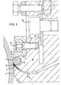
- the structure of the draining nozzle lip can best be seen from FIG. 3.
- the doctor rod 6 is mounted in a two-part doctor bearing.
- the squeegee bearing part 9 is screwed to the squeegee bearing part 10 by means of a clamping bar 19 and clamping screws 20.
- the doctor bearing part 9 is first slightly tightened with the tensioning screws 20. Thereafter, the distance between the squeegee bearing part 9 and the squeegee bearing part 10 is adjusted by tapping lightly with a plastic hammer so that a cylindrically ground pin with a length of approximately 30 mm and 12 mm diameter, fit h. can be sucked through the entire bore length.
- the clamping screws 20 are now tightened.
- the holes are expanded with a conical machine reamer in such a way that conical pins 21 with withdrawal threads 22 reproducibly position the doctor bearing part 9 and the doctor bearing part 10 in the set position.
- the squeegee bearing part 9 can be dismantled as often as required for cleaning purposes after pulling off the conical pins 21 and after loosening the tensioning screws 20.
- the doctor rod 6 together with its doctor bearing 9, 10 can be moved under tension by means of tension and compression screws 23 for clamping sealing strips 24 in the feed slot 25 to the nozzle, which limit the nozzle slot to the coating width.
- Tension and compression screws 26 are provided for influencing the coating profile.
- the doctor rod 6 is held with the help of the two doctor bearing parts 9, 10% of its circumference, so that its position and shape during its oscillating movement of the bore, which is provided with a fit seat H, remains adjusted.
- the doctor rod 6 itself is h. produced.
- a limited play occurs between the bore and the doctor rod 6, which is why coating material can also enter the doctor rod bearing, which serves as lubrication, but can accumulate in the longitudinal direction along the slot 8 between the two doctor bearing parts 9 and 10 up to the end plates 4 of the slot nozzle .
- the recesses 7 provided at the points described above ensure that the counter-pressure roller 1 does not come into contact without a superimposed material web 2 and that the slot 8 is sealed over the entire length of the doctor blade.
- the running nozzle lip in the form of the doctor rod 6 with the associated doctor bearing is designed as a flexible nozzle lip.
- the line of contact between the counter-pressure roller 1, the material web 2 and the oscillating doctor rod 6 along the web width can be influenced by means of the tension and compression screws 26. Corrections to the coating distribution can therefore be made.
- Another element for influencing the coating distribution is a flow restricting strip 27 in the feed channel 11 to the slot nozzle.
- This flow restricting strip 27 can be adjusted by means of tension and compression screws 28 in such a way that the flow distribution of the coating material is influenced over the web width.
- the flow restricting strip 27, also called choker bar, is mainly used for highly viscous compositions.
- the doctor rod 6 is usually made of steel, while the counter-pressure roller 1 is coated with rubber; the counter-pressure roller 1 can also be a chrome-plated steel roller. Alternatively, the doctor rod 6 can be made of hard rubber and the counter-pressure roller 1 can be a chrome-plated steel roller, which is ground with the highest precision.
- the concentricity should be 0.001 to 0.003 mm. These accuracies are necessary because the best possible distribution of the coating is sought. At 25 g / m 2 dry weight application, the fluctuations should not be more than ⁇ 1.5 g / m 2 ; 1 g / m 2 coating mass corresponds to a specific weight of 0.9 approximately 0.001 mm thickness of the coatings.
- doctor blades are used as the doctor rod.
- the coating weight is then determined by the wire thickness of the spiral doctor blade.
- Stainless piano side wires can be wound around the squeegee bar 6 in one or more threads. The coating material is pressed through the gaps between the wires.
- the coating has fine lines, which are not always desirable. If a spiral doctor blade is used as the doctor rod 6, the windings located in the doctor bearing must be sealed so that the coating material cannot run around the doctor rod 6 and settles on the material web 2 above the doctor rod 6.
- the semicircular bore in the squeegee bearing part 10 is first milled and then ground with a shaped grinding wheel.
- the bore section on the squeegee bearing part 9 is produced in a similar manner.
- the squeegee bearing part 9 is adjusted in height so that it forms part of a circle together with the semicircular bore.
- the hole is brushed in using cylindrical ground pins.
- the final setting is made after the nozzle lip and doctor blade bearing part 9 have been ionitrided to a surface hardness of 1000 to 1200 Vikkers.
Abstract
Description
Die Erfindung bezieht sich auf eine Vorrichtung zum Aufbringen einer dünnen Schicht eines Beschichtungsmaterials auf eine über eine Gegendruckwalze laufende Materialbahn mittels einer Schlitzdüseneinrichtung mit feststehender einlaufender und ablaufender Düsenlippe des Düsenschlitzes, insbesondere Breitdüsenschlitzes, bei der die ablaufende Düsenlippe als drehbarer Rakelstab in einem zweiteiligen Rakellager ausgebildet ist.The invention relates to a device for applying a thin layer of a coating material to a web of material running over a counter-pressure roller by means of a slot nozzle device with a fixed inlet and outlet nozzle lip of the nozzle slot, in particular a wide nozzle slot, in which the outlet nozzle lip is designed as a rotatable doctor rod in a two-part doctor blade bearing .
Durch die US-A Nr. 3919974 ist eine Schlitzdüseneinrichtung mit feststehenden Düsenlippen des Düsenschlitzes bekannt geworden, bei welcher die Düsenlippen zueinander zur Einstellung des Düsenschlitzes verstellbar sind. Eine derartige Schlitzdüseneinrichtung bedingt den Einsatz von Gegendruckwalzen mit genau der Beschichtungsbreite und Materialbahnbreite angepasster Länge. Eine Selbstreinigung der Düsenlippen zur Erzielung eines möglichst strichfreien Auftrages des Beschichtungsmaterials ist nicht vorgesehen.From US-A No. 3919974 a slot nozzle device with fixed nozzle lips of the nozzle slot is known, in which the nozzle lips are adjustable relative to one another for adjusting the nozzle slot. Such a slot nozzle device requires the use of counter-pressure rollers with a length that is precisely adapted to the coating width and material web width. There is no provision for self-cleaning of the nozzle lips in order to achieve the most coating-free application of the coating material.
Durch die US-A Nr. 2946307 ist eine Beschichtungsvorrichtung bekannt geworden, bei welcher das Beschichtungsmaterial entweder über eine Schöpfwalze auf die zu beschichtende Materialbahn aufgebracht und dann mittels einer Rollrakel abgerakelt wird oder in einem Sumpf zwischen der über eine Leitwalze laufenden Materialbahn und der Rollrakel aufgebracht wird. Die Vorteile eines Schlitzdüsenauftrags lassen sich mit einer derartigen Vorrichtung nicht erreichen.From US-A No. 2946307 a coating device has become known in which the coating material is either applied to the material web to be coated via a scoop roller and then doctored off by means of a doctor blade or applied in a sump between the material web running over a guide roller and the doctor blade becomes. The advantages of a slot nozzle application cannot be achieved with such a device.
Eine Vorrichtung der eingangs beschriebenen Art ist durch die DE-A Nr. 1964908 bekannt geworden. Eines der beiden Rakellagerteile wird dort von einem mit variierbarem Anpressdruck an dem Rakelstab anliegenden Reinigungsspachtel gebildet.A device of the type described in the introduction is known from DE-A No. 1964908. One of the two squeegee bearing parts is formed there by a cleaning spatula resting on the squeegee rod with a variable contact pressure.
Bei allen diesen bekannten Beschichtungseinrichtungen muss je nach Breite der Materialbahn die Gegendruckwalze in ihrer Länge genau auf die Materialbahnbreite abgestellt sein, um eine Verunreinigung der Gegendruckwalze ausserhalb der Beschichtungsbreite sowie ein Reiben der ablaufenden Düsenlippe auf der Gegendruckwalze ohne dazwischenliegende Materialbahn zu vermeiden.In all of these known coating devices, depending on the width of the material web, the length of the counter-pressure roller must be set exactly to the width of the material web in order to avoid contamination of the counter-pressure roller outside the coating width and rubbing of the running nozzle lip on the counter-pressure roller without an intermediate material web.
Der Erfindung liegt die Aufgabe zugrunde, eine Vorrichtung der eingangs beschriebenen Art zu schaffen, welche den Einsatz bzw. das Auswechseln besonderer Gegendruckwalzen für unterschiedliche Materialbahnbreiten überflüssig macht und auch bei längeren Produktionszeiten praktisch über Tage hin von Beschichtungsmittel freie Enden der Gegendruckwalze sicherstellt.The invention has for its object to provide a device of the type described above, which makes the use or replacement of special counter-pressure rollers for different web widths superfluous and ensures practically days of coating agent free ends of the counter-pressure roller even with longer production times.
Diese Aufgabe wird erfindungsgemäss dadurch gelöst, dass der Rakelstab ausserhalb der Bahnbreite mit segmentförmigen Ausnehmnungen versehen und derart oszillierend angetrieben ist, dass die segmentförmigen Ausnehmungen nicht in Verbindung mit den Schlitzen zwischen den beiden Rakellagerteilen kommen können.This object is achieved according to the invention in that the doctor rod outside the web width is provided with segment-shaped recesses and is driven in an oscillating manner in such a way that the segment-shaped recesses cannot come into contact with the slots between the two doctor blade bearing parts.
Durch diese Ausbildung der ablaufenden Düsenlippe bzw. des Rakelstabs ist sichergestellt, dass zwar der Rakelstab in seiner Lagerung durch das Beschichtungsmaterial ausreichend geschmiert ist, dass jedoch kein Beschichtungsmaterial in einen Bereich ausserhalb der vorgesehenen Beschichtungsbreite und damit über die Materialbahnbreite hinaus auf die Gegendruckwalze austreten kann.This configuration of the running nozzle lip or the doctor rod ensures that the doctor rod is sufficiently lubricated in its storage by the coating material, but that no coating material can escape into the area outside the intended coating width and thus beyond the material web width onto the counter-pressure roller.
Der Rakelstab ist für jede gewünschte Beschichtungs- und Bahnbreite auf einfache Weise herstellbar und auswechselbar.The doctor rod can be produced and exchanged in a simple manner for any desired coating and web width.
Vorteilhaft ist der Rakelstab fest mit einem Gestänge verbunden, welches seinerseits leicht lösbar mit einem Antrieb für den Rakelstab in Verbindung steht.The doctor rod is advantageously firmly connected to a linkage, which in turn is easily releasably connected to a drive for the doctor rod.
Weiter sind zweckmässig in dem Düsenschlitz im Bereich ausserhalb der Bahnbreite Dichtstreifen eingelegt.Furthermore, sealing strips are expediently inserted in the nozzle slot in the area outside the web width.
Sollen zwei oder mehr getrennte Bahnen in einer Beschichtungsvorrichtung nebeneinander laufend beschichtet werden, so weist der Rakelstab vorteilhaft mehrere segmentförmige Ausnehmungen entlang seiner Länge auf, und zwar jeweils an den Stellen, wo die Gegenwalze nicht von einer zu beschichtenden Materialbahn überdeckt ist.If two or more separate webs are to be coated side by side in a coating device, the doctor bar advantageously has a plurality of segment-shaped recesses along its length, in each case at the points where the counter-roller is not covered by a material web to be coated.
Der Rakelstab kann aus Stahl und die Gegendruckwalze mit einem elastischen Material wie Hartgummi, Kautschuk und dergleichen beschichtet sein. Alternativ kann der Rakelstab aus Hartgummi und die Gegendruckwalze eine verchromte Stahlwalze sein.The doctor rod can be made of steel and the counter-pressure roller can be coated with an elastic material such as hard rubber, rubber and the like. Alternatively, the hard rubber doctor rod and the counter-pressure roller can be a chrome-plated steel roller.
Zur einfachen und genauen Herstellung der ablaufenden Düsenlippe sind die beiden Rakellagerteile zweckmässig miteinander verschraubt und mittels konischer Stifte in ihrer Lage zueinander fixiert.For simple and precise manufacture of the running nozzle lip, the two doctor bearing parts are expediently screwed together and fixed in their position relative to one another by means of conical pins.
Um einen besonders gleichmässigen Auftrag von Beschichtungsmaterial zu erhalten, kann der Rakelstab auch als Spiralrakel ausgebildet sein.In order to obtain a particularly uniform application of coating material, the doctor rod can also be designed as a spiral doctor.
Zweckmässig ist die ablaufende Düsenlippe mit Rakelstab als flexible Düsenlippe mittels Zug- und Druckschrauben in ihrer Berührungslinie mit der Materialbahn und der Gegendruckwalze einstellbar. Hiermit lässt sich eine gleichmässige Verteilung der Beschichtungsdicke auf einfache Weise einstellen.The running-off nozzle lip with a doctor blade rod is expediently adjustable as a flexible nozzle lip by means of tension and compression screws in its line of contact with the material web and the counter-pressure roller. This makes it easy to set a uniform distribution of the coating thickness.
Als weiteres Element zur Beeinflussung der Beschichtungsverteilung kann in der Zuleitung zur Schlitzdüse eine im Düsenkörperteil des Rakelstabes eingebaute, mittels Zug- und Druckschrauben verstellbare Strömungshemmleiste vorgesehen sein.As a further element for influencing the coating distribution, a flow inhibitor strip which is installed in the nozzle body part of the doctor rod and which can be adjusted by means of tension and compression screws can be provided in the feed line to the slot nozzle.
Die Schlitzdüseneinrichtung ist zweckmässig seitlich neben der Gegendruckwalze zu dieser hin verstellbar und drehbar eingebaut. Dabei ist die einlaufende Düsenlippe der als Breitschlitzdüse ausgebildeten Schlitzdüse vorteilhaft als Dichtlippe ausgebildet.The slot nozzle device is expediently adjustable and rotatably installed laterally next to the counter-pressure roller. The incoming nozzle lip of the slot nozzle designed as a wide slot nozzle is advantageously designed as a sealing lip.
Mit der erfindungsgemässen Ausbildung der Aufbring- und Beschichtungsvorrichtung wird erreicht, dass die Gegendruckwalze immer unverändert in der Vorrichtung verbleiben kann, während durch die besondere Ausbildung der ablaufenden Düsenlippe mit Rakelstab und Ausbildung und Antrieb dieses Rakelstabes sowohl ein Austreten von Beschichtungsmaterial ausserhalb der zu beschichtenden Materialbahn als auch eine Berührung der ablaufenden Düsenlippe in Form des Rakelstabes mit der Gegendruckwalze ausserhalb der zu beschichtenden Materialbahn sicher vermieden wird. Dies ist besonders wichtig bei dünnen Schichten der Grössenordnung von Auftragsmengen von 1 bis 40 g/m2.With the design of the application and coating device according to the invention it is achieved that the counter-pressure roller can always remain unchanged in the device, while due to the special design of the running nozzle lip with a doctor bar and the design and drive of this doctor bar, both leakage coating material outside of the material web to be coated and contact of the running nozzle lip in the form of the doctor rod with the counter-pressure roller outside of the material web to be coated is reliably avoided. This is particularly important for thin layers on the order of 1 to 40 g / m 2 .
Die Erfindung ist im folgenden an einem Ausführungsbeispiel anhand der Zeichnungen näher erläutert. In den Zeichnungen zeigen:
- Fig. 1 eine Draufsicht auf eine Beschichtungsvorrichtung gemäss der Erfindung in schematischer Darstellung,
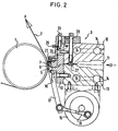
- Fig. 2 eine Seitenansicht der Beschichtungsvorrichtung nach Fig. 1, gesehen von links in Fig. 1, und
- Fig. 3 eine Seitenansicht der Beschichtungsdüse der Vorrichtung in Fig. 1 in vergrösserter Darstellung.
- 1 is a plan view of a coating device according to the invention in a schematic representation,
- FIG. 2 shows a side view of the coating device according to FIG. 1, seen from the left in FIG. 1, and
- Fig. 3 is a side view of the coating nozzle of the device in Fig. 1 in an enlarged view.
Die erfindungsgemässe Vorrichtung zum Aufbringen einer dünnen Schicht eines Beschichtungsmaterials weist eine Gegendruckwalze 1 auf, welche mit Kautschuk oder Hartgummi bezogen ist. Über die Gegendruckwalze 1 wird in Richtung des Pfeiles A eine zu beschichtende Materialbahn 2 mit einer Bahnbreite a geführt. Die Beschichtungsbreite b ist kleiner als die Bahnbreite, während die Breite c der Gegendruckwalze 1 grösser als die Bahnbreite a ist.The device according to the invention for applying a thin layer of a coating material has a
Auf einer Seite der Gegendruckwalze 1 ist eine Schlitzdüseneinrichtung 3 mit feststehender einlaufender und ablaufender Düsenlippe des Düsenschlitzes vorgesehen. Die Breite der Schlitzdüse ist mit d bezeichnet. Auf beiden Stirnseiten der Schlitzdüseneinrichtung sind Abschlussplatten 4 vorgesehen.On one side of the
Zu beschichtende Materialbahnen 2 sind beispielsweise Papierbahnen, Kunststoffolien, Metallfolien, Gewebebahnen sowie Kombinationen derartiger Materialbahnen. So kann die Materialbahn 2 eine Aluminiumfolie mit 0,008,0,012,0,02 und bis zu 0,12 mm Dicke sein. Als Papierbahnen kommen glatte, gestrichene oder gekreppte Papiere von 40 bis 120 g/m2 in Frage, als Kunststofffolien Polyäthylenfolien von 40 bis 120 11m Dicke, biaxial gereckte, sogenannte orientierte Polypropylenfolien von 30 bis 120 11m Dicke und Polyesterfolien im gleichen Dickenbereich. Weiter können als Materialbahnen zwei Hart-PVC-Folien und monomer sowie polymer weichgemachte PVC-Folien verarbeitet werden, und als Gewebebahnen beispielsweise Teppichverlegebänder und Verbandsmaterialien.Material webs 2 to be coated are, for example, paper webs, plastic films, metal foils, fabric webs and combinations of such material webs. The material web 2 can be an aluminum foil with 0.008.0.012.0.02 and up to 0.12 mm thick. Smooth, coated or creped papers from 40 to 120 g / m 2 are possible as paper webs, polyethylene films from 40 to 120 11m thick, biaxially oriented, so-called oriented polypropylene films from 30 to 120 11m thick and polyester films in the same thickness range as plastic films. Furthermore, two hard PVC foils and monomeric and polymer softened PVC foils can be processed as material webs, and, for example, carpet laying tapes and dressing materials as fabric webs.
Beschichtungsmaterialien sind unter anderem Paraffine und mikrokristalline Wachse mit Verarbeitungstemperaturen zwischen 75 und 100°C bei Auftragsmengen zwischen 4 und 40 g/m2. Weiter kommen in Frage Beschichtungshotmelts, bestehend aus Äthylvinylacetatcopolymeren, gemischt mit Paraffin und Harzen, bei Verarbeitungstemperaturen zwischen 140 und 190°C für die Oberflächenveredelung von Verpackungsmaterial. Verwendete Schmelzhaftkleber haben Verarbeitungstemperaturen zwischen 140 und 190°C bei Auftragsmengen zwischen 12 und 40 g/m2, während Thermosetkleber bei Temperaturen von 70 bis 80°C und Auftragsmengen ab 40 g/m2 verarbeitet werden. Polyurethankleber, bestehend aus zwei Komponenten, werden kurz vor der Beschichtung gemischt.Coating materials include paraffins and microcrystalline waxes with processing temperatures between 75 and 100 ° C with application quantities between 4 and 40 g / m 2 . Coating hotmelts, consisting of ethyl vinyl acetate copolymers, mixed with paraffin and resins, are also suitable at processing temperatures between 140 and 190 ° C for the surface finishing of packaging material. Hot melt pressure sensitive adhesives used have processing temperatures between 140 and 190 ° C with application quantities between 12 and 40 g / m 2 , while thermoset adhesives are processed at temperatures from 70 to 80 ° C and application quantities from 40 g / m 2 . Polyurethane glue, consisting of two components, is mixed shortly before coating.
Weitere Beschichtungsmaterialien sind wässerige Emulsionen und Dispersionen als PVDC-Beschichtung bei Raumtemperatur, Acrylatkleber als wässerige Dispersionen mit Beschichtung ebenfalls bei Raumtemperatur, verschiedene Stärkekleber, die bei Temperaturen von 70 bis 90°C verarbeitet werden, Klebstoffe und Beschichtungsmassen, die in organischen Lösungsmitteln gelöst sind und bei Raumtemperatur verarbeitet werden und schliesslich Kaltleime PVC auf der Basis von Polyvinylalkohol.Other coating materials include aqueous emulsions and dispersions as PVDC coatings at room temperature, acrylate adhesives as aqueous dispersions with coatings also at room temperature, various starch adhesives that are processed at temperatures from 70 to 90 ° C, adhesives and coating compounds that are dissolved in organic solvents and processed at room temperature and finally cold glue PVC based on polyvinyl alcohol.
Die einlaufende Düsenlippe 5 der Schlitzdüseneinrichtung 3 ist feststehend ausgebildet. Die ablaufende Düsenlippe der Schlitzdüse ist als drehbarer Rakelstab 6 ausgebildet. Der Rakelstab 6 weist ausserhalb der Bahnbreite a bis über die Walzenbreite c hinausreichende segmentförmige Ausnehmungen 7 auf, durch welche der Rakelstab 6 ähnlich einer Schlüsselfläche abgesetzt ist. Hierdurch bleibt das gesamte Rakelstablager durch den vollen Rakelstab ausgefüllt und es gibt für das Beschichtungsmaterial keine Möglichkeit, sich in solchen Hohlräumen anzusammeln, was zu einem Austreten des Beschichtungsmaterials an unerwünschten Stellen führen könnte. Auch die für die Herstellung des Rakelstablagers unvermeidlichen Schlitze 8 zwischen zwei Rakellagerteilen 9 und 10 sind ständig durch den Rakelstab 6 verschlossen.The
Der Schlitzdüseneinrichtung 3 wird über einen Beschichtungsmaterialkanal 11 Beschichtungsmaterial zugeführt. Der Beschichtungsmaterialkanal 11 befindet sich an der Trennstelle zwischen einer oberen Düsenhälfte 12 und einer unteren Düsenhälfte 13. In den Düsenhälften 12 und 13 sind Heizungs- bzw. Kühlbohrungen 14 vorgesehen.The
Der die ablaufende Düsenlippe bildende Rakelstab 6 wird über einen Betriebmotor 15, einen Pleuel 16 und ein fest mit der Rakelstab 6 verbundenes Gestänge 17 derart oszillierend angetrieben, dass der Rakelstab 6 einerseits ständig die Schlitze 8 zwischen den beiden Rakellagerteilen 9 und 10 abdichtet, andererseits aber aufgrund seiner segmentförmigen Ausnehmungen 7 ausserhalb der Materialbahn 2 nicht in Berührung mit der Gegendruckwalze 1 kommen kann. Hierdurch wird eine Beschädigung der Gegendruckwalze 1 durch den Rakelstab 6 sicher vermieden, während gleichzeitig gewährleistet ist, dass kein Beschichtungsmaterial auf die Gegendruckwalze 1 austreten kann.The
Der Pleuel 16 lässt sich leicht von dem Gestänge 17 lösen, worauf der Rakelstab 6 einfach aus der Rakellagerung herausgezogen und durch einen einer geänderten Bahnbreite a angepassten Rakelstab ersetzt werden kann.The connecting
Der Getriebemotor 15 hat eine Drehzahl von 9 bis 11 tr/min und ergibt eine entsprechend oszillierende Bewegung des Rakelstabes 6, wodurch der Rakeleffekt für die ablaufende Düsenlippe erreicht und damit eine Streifenbildung bei der Beschichtung sicher vermieden wird.The geared
DieSchlitzdüseneinrichtung 3 kann durch einen nicht gezeigten Drehmechanismus derart gedreht werden, dass die feststehende einlaufende Düsenlippe 5 leicht an der Materialbahn 2 anliegt und eine Dichtwirkung erzielt, so dass kein Beschichtungsmaterial nach unten herausläuft und trotzdem keine nennenswerte Reibung zwischen den überstehenden Enden der Gegendruckwalze 1 und der Düsenlippe 5 entsteht. Die feststehende einlaufende Düsenlippe 5 ist mit der unteren Düsenhälfte 13 verschraubt und weist ein Ableitblech 18 auf.The
Der Aufbau der ablaufenden Düsenlippe ist am besten aus Fig. 3 zu erkennen. Der Rakelstab 6 ist in einem zweiteiligen Rakellager gelagert. Das Rakellagerteil 9 ist gegenüber dem Rakellagerteil 10 mittels einer Spannleiste 19 und Spannschrauben 20verschraubt. Das Rakellagerteil 9 wird zunächst mit den Spannschrauben 20 leicht angezogen. Danach wird durch leichtes Klopfen mittels eines Kunststoffhammers der Abstand zwischen dem Rakellagerteil 9 und dem Rakellagerteil 10 so eingestellt, dass ein zylindrisch geschliffener Stift mit einer Länge von etwa 30 mm und 12 mm Durchmesser, Passung h. saugend durch die gesamte Bohrungslänge geschoben werden kann. Die Spannschrauben 20 werden jetzt angezogen.The structure of the draining nozzle lip can best be seen from FIG. 3. The
Zwischen den Spannschrauben 20 des als Klemmleiste ausgebildeten Rakellagerteils 9, die etwa in einem Abstand von 100 mm angeordnet sind, befinden sich in dem Rakellagerteil 9 vorgebohrte Löcher. Nachdem die Endeinstellung stattgefunden hat, werden diese vorgebohrten Löcher weiter aufgebohrt und in das Rakellagerteil 10 vorgetrieben. Mit einer konischen Maschinenreibahle werden die Löcher derart erweitert, dass konische Stifte 21 mit Abzugsgewinden 22 das Rakellagerteil 9 und das Rakellagerteil 10 in der eingestellten Lage reproduzierbar positionieren. Das Rakellagerteil 9 kann nach Abziehen der konischen Stifte 21 und nach Lösen der Spannschrauben 20 beliebig oft zu Reinigungszwecken demontiert werden.There are pre-drilled holes in the
Der Rakelstab 6 samt seinem Rakellager 9, 10 kann mittels Zug- und Druckschrauben 23 zum Einspannen von Dichtstreifen 24 in den Zuführungsschlitz 25 zu der Düse, die den Düsenschlitz auf die Beschichtungsbreite begrenzen, unter Spannung verschoben werden. Für die Beschichtungsprofilbeeinflussung sind Zug- und Druckschrauben 26 vorgesehen.The
Der Rakelstab 6 wird mit Hilfe der beiden Rakellagerteile 9,10 über % seines Umfanges festgehalten, damit seine Lage und Form während seiner oszillierenden Bewegung der Bohrung, die mit einem Passungssitz H, versehen ist, angepasst bleibt. Der Rakelstab 6 selbst wird mit einem Passungssitz h. hergestellt. Zwischen Bohrung und Rakelstab 6 tritt also ein begrenztes Spiel auf, weshalb auch in das Rakelstablager Beschichtungsmaterial eintreten kann, das als Schmierung dient, sich jedoch in Längsrichtung entlang dem Schlitz 8 zwischen den beiden Rakellagerteilen 9 und 10 bis zu den Abschlussplatten 4 der Schlitzdüse ansammeln kann. Die an den oben beschriebenen Stellen angebrachten Ausnehmungen 7 stellen die Berührungsfreiheit der Gegendruckwalze 1 ohne überlagernde Materialbahn 2 sowie die Abdichtung des Schlitzes 8 über die gesamte Rakelstablänge sicher.The
Die ablaufende Düsenlippe in Form des Rakelstabes 6 mit zugehörigem Rakellager ist als flexible Düsenlippe ausgebildet. Mittels der Zug- und Druckschrauben 26 kann die Berührungslinie zwischen der Gegendruckwalze 1, der Materialbahn 2 und dem oszillierenden Rakelstab 6 entlang der Bahnbreite beeinflusst werden. Es können also Korrekturen der Beschichtungsverteilung vorgenommen werden.The running nozzle lip in the form of the
Ein weiteres Element zur Beeinflussung der Beschichtungsverteilung ist eine Strömungshemmleiste 27 im Zuführungskanal 11 zu der Schlitzdüse. Diese Strömungshemmleiste 27 kann mittels Zug- und Druckschrauben 28 derart verstellt werden, dass die Strömungsverteilung des Beschichtungsmaterials über die Bahnbreite beeinflusst wird. Die Strömungshemmleiste 27, auch Chokerbar genannt, findet hauptsächlich bei hochviskosen Massen Verwendung. Mit den erfindungsgemässen Schlitzdüseneinrichtungen sind Beschichtungsmaterialien in einem Viskositätsbereich von dem von Wasser bis 2500 Pa - s verarbeitbar. Die Auftragsgewichte liegen zwischen 1 und 400 g/m2. Another element for influencing the coating distribution is a
Der Rakelstab 6 besteht normalerweise aus Stahl, während die Gegendruckwalze 1 mit Kautschuk beschichtet ist; die Gegendruckwalze 1 kann auch eine verchromte Stahlwalze sein. Alternativ kann der Rakelstab 6 aus Hartgummi bestehen und die Gegendruckwalze 1 eine verchromte Stahlwalze sein, welche mit höchster Präzision geschliffen ist. Die Rundlaufgenauigkeit soll 0,001 bis 0,003 mm betragen. Diese Genauigkeiten sind erforderlich, weil eine möglichst gute Verteilung der Beschichtung angestrebt wird. Bei 25 g/m2 Trockengewichtsauftrag sollen die Schwankungen nicht mehr als ± 1,5 g/m2 sein; 1 g/m2 Beschichtungsmasse entspricht bei einem spezifischen Gewicht von 0,9 etwa 0,001 mm Dicke der Beschichtungen.The
Für Beschichtungen, die eine sehr gute Verteilung unabhängig von Schwankungen der Materialbahn 2 aufweisen sollen, werden als Rakelstab 6 Spiralrakel verwendet. Das Beschichtungsgewichtwird dann durch die Drahtdicke der Spiralrakel bestimmt. Rostfreie Klavierseitendrähte können eingängig oder mehrgängig um den Rakelstab 6 gewickelt werden. Das Beschichtungsmaterial wird durch die entstehenden Zwischenräume zwischen den Drähten untereinander durchgepresst.For coatings that should have a very good distribution regardless of fluctuations in the
Die Beschichtung weist jedoch feine Linien auf, welche nicht immer erwünscht sind. Bei Verwendung einer Spiralrakel als Rakelstab 6 müssen die im Rakellager befindlichen Windungen abgedichtet werden, damit das Beschichtungsmaterial nicht um den Rakelstab 6 herumlaufen kann und sich oberhalb des Rakelstabes 6 auf der Materialbahn 2 absetzt.However, the coating has fine lines, which are not always desirable. If a spiral doctor blade is used as the
Bei der Herstellung der ablaufenden Düsenlippe mit Rakelstab 6 ist darauf zu achten, dass die beiden Rakellagerteile 9 und 10 beispielsweise eine Bohrung bilden, deren Passungssitz 12 mm Durchmesser H, beträgt. Die Passung muss auf der ganzen Länge der Schlitzdüse bis zu 2600 mm und mehr stimmen. Nur dann lässt sich der Rakelstab 6 leicht ein- und ausschieben.When manufacturing the running nozzle lip with
Die halbrunde Bohrung in dem Rakellagerteil 10 wird zunächst gefräst und anschliessend mit einer Formschleifscheibe geschliffen. Ähnlich wird das Bohrungsteilstück an dem Rakellagerteil 9 hergestellt. Danach wird das Rakellagerteil 9 in seiner Höhe so angepasst, dass es zusammen mit der Halbrundbohrung einen Teil eines Kreises bildet. Die Bohrung wird mittels zylindrischen geschliffenen Stiften eintuschiert. Die Endeinstellung erfolgt, nachdem Düsenlippe und Rakellagerteil 9 auf eine Oberflächenhärte von 1000 bis 1200 Vikkers ionitriert sind.The semicircular bore in the
Claims (12)
Priority Applications (2)
| Application Number | Priority Date | Filing Date | Title |
|---|---|---|---|
| AT81100219T ATE9967T1 (en) | 1981-01-14 | 1981-01-14 | DEVICE FOR APPLYING A THIN LAYER OF COATING MATERIAL TO A RUNNING WEB OF MATERIAL. |
| EP81100219A EP0056067B1 (en) | 1981-01-14 | 1981-01-14 | Apparatus for applying a thin layer of a coating substance to a travelling material web |
Applications Claiming Priority (1)
| Application Number | Priority Date | Filing Date | Title |
|---|---|---|---|
| EP81100219A EP0056067B1 (en) | 1981-01-14 | 1981-01-14 | Apparatus for applying a thin layer of a coating substance to a travelling material web |
Publications (2)
| Publication Number | Publication Date |
|---|---|
| EP0056067A1 EP0056067A1 (en) | 1982-07-21 |
| EP0056067B1 true EP0056067B1 (en) | 1984-10-24 |
Family
ID=8187531
Family Applications (1)
| Application Number | Title | Priority Date | Filing Date |
|---|---|---|---|
| EP81100219A Expired EP0056067B1 (en) | 1981-01-14 | 1981-01-14 | Apparatus for applying a thin layer of a coating substance to a travelling material web |
Country Status (2)
| Country | Link |
|---|---|
| EP (1) | EP0056067B1 (en) |
| AT (1) | ATE9967T1 (en) |
Families Citing this family (6)
| Publication number | Priority date | Publication date | Assignee | Title |
|---|---|---|---|---|
| IT8267442A0 (en) * | 1982-04-05 | 1982-04-05 | Rotomec Costr Mecc | DEVICE FOR SPREADING A SUBSTANCE ONTO A TAPE MATERIAL |
| AT387161B (en) * | 1987-05-18 | 1988-12-12 | Zimmer Johannes | DEVICE FOR SUPPLYING A FLOWABLE SUBSTANCE |
| DE19722117C2 (en) * | 1997-05-27 | 2000-09-07 | Bematec S A | Coating of porous supports |
| DE10333121B4 (en) | 2003-07-21 | 2006-01-19 | Kodak Polychrome Graphics Gmbh | Apparatus and method for coating material |
| CN114700232B (en) * | 2022-04-09 | 2023-02-03 | 深圳市智力昌智能设备有限公司 | Coating, drying and rolling mill |
| CN115290542B (en) * | 2022-07-12 | 2023-05-23 | 深圳中氟科技有限公司 | Test system for insulating coating performance |
Family Cites Families (6)
| Publication number | Priority date | Publication date | Assignee | Title |
|---|---|---|---|---|
| DE1235723B (en) * | 1961-11-08 | 1967-03-02 | Eck & Soehne Joseph | Coating head of a paper coating machine |
| DE1291654C2 (en) * | 1965-09-07 | 1974-11-14 | Schölten, Dipl.-Ing. Jürgen, AlOO Duisburg | COATING DEVICE FOR PAINT |
| SE360408B (en) * | 1968-12-30 | 1973-09-24 | Waertsilae Oy Ab | |
| JPS584589B2 (en) * | 1976-08-12 | 1983-01-27 | 富士写真フイルム株式会社 | Application method |
| US4167914A (en) * | 1977-05-25 | 1979-09-18 | Bolton-Emerson, Inc. | Rotating rod, rotating press roll nip coating apparatus |
| JPS5430021A (en) * | 1977-08-11 | 1979-03-06 | Fuji Photo Film Co Ltd | Consecutive application of both sides |
-
1981
- 1981-01-14 EP EP81100219A patent/EP0056067B1/en not_active Expired
- 1981-01-14 AT AT81100219T patent/ATE9967T1/en not_active IP Right Cessation
Also Published As
| Publication number | Publication date |
|---|---|
| ATE9967T1 (en) | 1984-11-15 |
| EP0056067A1 (en) | 1982-07-21 |
Similar Documents
| Publication | Publication Date | Title |
|---|---|---|
| EP0003790B1 (en) | Device for coating a moving web | |
| DE2452784C3 (en) | Method and apparatus for continuously coating a strip of material, for example a paper web | |
| AT392602B (en) | COATING DEVICE FOR COATING RUNNING PRODUCTS | |
| DE3927680A1 (en) | APPLICATION DEVICE | |
| AT396436B (en) | DEVICE AND METHOD FOR COATING CONTINUOUS GOODS | |
| DE3931793A1 (en) | A DEVICE FOR COATING A DRIVING TRAIN | |
| DE4446308C2 (en) | Device for applying a liquid or pasty medium to a running web of material | |
| EP0791687A1 (en) | Process and device for coating a liquid or pasty material onto a moving web | |
| DE2504701C2 (en) | Method and device for double-sided coating of a web moving from bottom to top | |
| DE19722117C2 (en) | Coating of porous supports | |
| EP0301061B1 (en) | Applicator with rolling scraper for applying coatings on webs of material | |
| EP0056067B1 (en) | Apparatus for applying a thin layer of a coating substance to a travelling material web | |
| EP0108887B1 (en) | Coating apparatus | |
| DE102009026495A1 (en) | doctor device | |
| DE2611625C3 (en) | ||
| CH666835A5 (en) | DEVICE FOR OPTIONALLY SINGLE OR DOUBLE-SIDED COATING OF A RUNNING PAPER, AND METHOD FOR OPERATING THE DEVICE. | |
| EP0071149B1 (en) | Apparatus for the weight control of coatings on a travelling web | |
| DE2944393C2 (en) | Device for applying a thin layer of a coating material to a moving material web | |
| EP0055867B1 (en) | Apparatus for applying a thin layer of a coating material to a substrate | |
| DE2633111A1 (en) | Magnetic tape coating machine - has height adjustable resilient spreader roller or block following coating substance distributor | |
| CH656559A5 (en) | DEVICE FOR ONE- OR TWO-SIDED COATING OF RAILWAY MATERIAL. | |
| EP0120482B1 (en) | Device for applying a layer of fine ceramic material to a carrier | |
| DE19527902B4 (en) | Application system for a device for coating a paper or cardboard web | |
| DE3321389A1 (en) | SIMPLE APPLICATION DEVICE | |
| DE3120716A1 (en) | Process and device for feeding a coating material onto a moving web under pressure |
Legal Events
| Date | Code | Title | Description |
|---|---|---|---|
| PUAI | Public reference made under article 153(3) epc to a published international application that has entered the european phase |
Free format text: ORIGINAL CODE: 0009012 |
|
| 17P | Request for examination filed |
Effective date: 19811009 |
|
| AK | Designated contracting states |
Designated state(s): AT CH FR GB IT SE |
|
| ITF | It: translation for a ep patent filed |
Owner name: BARZANO' E ZANARDO MILANO S.P.A. |
|
| GRAA | (expected) grant |
Free format text: ORIGINAL CODE: 0009210 |
|
| AK | Designated contracting states |
Designated state(s): AT CH FR GB IT LI SE |
|
| REF | Corresponds to: |
Ref document number: 9967 Country of ref document: AT Date of ref document: 19841115 Kind code of ref document: T |
|
| ET | Fr: translation filed | ||
| PLBE | No opposition filed within time limit |
Free format text: ORIGINAL CODE: 0009261 |
|
| STAA | Information on the status of an ep patent application or granted ep patent |
Free format text: STATUS: NO OPPOSITION FILED WITHIN TIME LIMIT |
|
| 26N | No opposition filed | ||
| ITPR | It: changes in ownership of a european patent |
Owner name: CESSIONE;BEMATEC S.A. |
|
| REG | Reference to a national code |
Ref country code: CH Ref legal event code: PUE Owner name: BEMATEC S.A. |
|
| REG | Reference to a national code |
Ref country code: GB Ref legal event code: 732 |
|
| REG | Reference to a national code |
Ref country code: FR Ref legal event code: TP |
|
| ITTA | It: last paid annual fee | ||
| EAL | Se: european patent in force in sweden |
Ref document number: 81100219.5 |
|
| PGFP | Annual fee paid to national office [announced via postgrant information from national office to epo] |
Ref country code: SE Payment date: 19981210 Year of fee payment: 19 |
|
| PGFP | Annual fee paid to national office [announced via postgrant information from national office to epo] |
Ref country code: FR Payment date: 19990112 Year of fee payment: 19 |
|
| PGFP | Annual fee paid to national office [announced via postgrant information from national office to epo] |
Ref country code: AT Payment date: 19990121 Year of fee payment: 19 |
|
| PGFP | Annual fee paid to national office [announced via postgrant information from national office to epo] |
Ref country code: GB Payment date: 19990128 Year of fee payment: 19 |
|
| PGFP | Annual fee paid to national office [announced via postgrant information from national office to epo] |
Ref country code: CH Payment date: 19990204 Year of fee payment: 19 |
|
| PG25 | Lapsed in a contracting state [announced via postgrant information from national office to epo] |
Ref country code: GB Free format text: LAPSE BECAUSE OF NON-PAYMENT OF DUE FEES Effective date: 20000114 Ref country code: AT Free format text: LAPSE BECAUSE OF NON-PAYMENT OF DUE FEES Effective date: 20000114 |
|
| PG25 | Lapsed in a contracting state [announced via postgrant information from national office to epo] |
Ref country code: SE Free format text: LAPSE BECAUSE OF NON-PAYMENT OF DUE FEES Effective date: 20000115 |
|
| PG25 | Lapsed in a contracting state [announced via postgrant information from national office to epo] |
Ref country code: LI Free format text: LAPSE BECAUSE OF NON-PAYMENT OF DUE FEES Effective date: 20000131 Ref country code: CH Free format text: LAPSE BECAUSE OF NON-PAYMENT OF DUE FEES Effective date: 20000131 |
|
| GBPC | Gb: european patent ceased through non-payment of renewal fee |
Effective date: 20000114 |
|
| EUG | Se: european patent has lapsed |
Ref document number: 81100219.5 |
|
| REG | Reference to a national code |
Ref country code: CH Ref legal event code: PL |
|
| PG25 | Lapsed in a contracting state [announced via postgrant information from national office to epo] |
Ref country code: FR Free format text: LAPSE BECAUSE OF NON-PAYMENT OF DUE FEES Effective date: 20000929 |
|
| REG | Reference to a national code |
Ref country code: FR Ref legal event code: ST |