EP0056014A2 - Dispositif pour le captage et le transport de poussières - Google Patents
Dispositif pour le captage et le transport de poussières Download PDFInfo
- Publication number
- EP0056014A2 EP0056014A2 EP82300046A EP82300046A EP0056014A2 EP 0056014 A2 EP0056014 A2 EP 0056014A2 EP 82300046 A EP82300046 A EP 82300046A EP 82300046 A EP82300046 A EP 82300046A EP 0056014 A2 EP0056014 A2 EP 0056014A2
- Authority
- EP
- European Patent Office
- Prior art keywords
- drillhole
- air
- flow
- chamber
- head
- Prior art date
- Legal status (The legal status is an assumption and is not a legal conclusion. Google has not performed a legal analysis and makes no representation as to the accuracy of the status listed.)
- Granted
Links
- 239000000428 dust Substances 0.000 title claims abstract description 95
- 238000005520 cutting process Methods 0.000 claims abstract description 105
- 238000005553 drilling Methods 0.000 claims abstract description 81
- 238000000926 separation method Methods 0.000 claims abstract description 44
- 239000000463 material Substances 0.000 claims description 96
- 239000011236 particulate material Substances 0.000 claims description 29
- 239000012530 fluid Substances 0.000 claims description 22
- 238000007789 sealing Methods 0.000 claims description 19
- 238000004891 communication Methods 0.000 claims description 17
- 230000005484 gravity Effects 0.000 claims description 13
- 230000002093 peripheral effect Effects 0.000 claims description 13
- 230000008859 change Effects 0.000 claims description 10
- 238000011044 inertial separation Methods 0.000 claims description 10
- 238000007599 discharging Methods 0.000 claims description 9
- 238000001914 filtration Methods 0.000 claims description 9
- 230000002452 interceptive effect Effects 0.000 claims description 2
- 230000004044 response Effects 0.000 claims description 2
- 239000002245 particle Substances 0.000 abstract description 26
- 239000003570 air Substances 0.000 description 208
- 238000005192 partition Methods 0.000 description 17
- 230000007246 mechanism Effects 0.000 description 15
- 239000013618 particulate matter Substances 0.000 description 14
- 230000002829 reductive effect Effects 0.000 description 12
- 238000004140 cleaning Methods 0.000 description 10
- 239000011362 coarse particle Substances 0.000 description 10
- 230000008878 coupling Effects 0.000 description 10
- 238000010168 coupling process Methods 0.000 description 10
- 238000005859 coupling reaction Methods 0.000 description 10
- 238000009527 percussion Methods 0.000 description 9
- 230000002441 reversible effect Effects 0.000 description 9
- 230000009467 reduction Effects 0.000 description 8
- 238000011068 loading method Methods 0.000 description 6
- 230000000737 periodic effect Effects 0.000 description 6
- 238000011010 flushing procedure Methods 0.000 description 5
- 238000000034 method Methods 0.000 description 5
- 230000015572 biosynthetic process Effects 0.000 description 4
- 239000010419 fine particle Substances 0.000 description 4
- 238000005755 formation reaction Methods 0.000 description 4
- 238000011161 development Methods 0.000 description 3
- 230000000694 effects Effects 0.000 description 3
- 230000003628 erosive effect Effects 0.000 description 3
- 230000006872 improvement Effects 0.000 description 3
- 230000000717 retained effect Effects 0.000 description 3
- 239000011435 rock Substances 0.000 description 3
- 230000009471 action Effects 0.000 description 2
- 238000013459 approach Methods 0.000 description 2
- 230000008901 benefit Effects 0.000 description 2
- 238000011109 contamination Methods 0.000 description 2
- 229910052751 metal Inorganic materials 0.000 description 2
- 239000002184 metal Substances 0.000 description 2
- 230000035515 penetration Effects 0.000 description 2
- 230000008569 process Effects 0.000 description 2
- 239000012858 resilient material Substances 0.000 description 2
- 238000005201 scrubbing Methods 0.000 description 2
- 230000003068 static effect Effects 0.000 description 2
- 238000005299 abrasion Methods 0.000 description 1
- 238000009825 accumulation Methods 0.000 description 1
- 239000012080 ambient air Substances 0.000 description 1
- 239000004927 clay Substances 0.000 description 1
- 238000005056 compaction Methods 0.000 description 1
- 230000006835 compression Effects 0.000 description 1
- 238000007906 compression Methods 0.000 description 1
- 238000013461 design Methods 0.000 description 1
- 238000006073 displacement reaction Methods 0.000 description 1
- 239000013013 elastic material Substances 0.000 description 1
- 239000013536 elastomeric material Substances 0.000 description 1
- 238000003912 environmental pollution Methods 0.000 description 1
- 238000013467 fragmentation Methods 0.000 description 1
- 238000006062 fragmentation reaction Methods 0.000 description 1
- 239000000383 hazardous chemical Substances 0.000 description 1
- 231100000206 health hazard Toxicity 0.000 description 1
- 229910001385 heavy metal Inorganic materials 0.000 description 1
- 229910052500 inorganic mineral Inorganic materials 0.000 description 1
- 238000004519 manufacturing process Methods 0.000 description 1
- 239000011707 mineral Substances 0.000 description 1
- 238000005065 mining Methods 0.000 description 1
- 230000000149 penetrating effect Effects 0.000 description 1
- 238000012545 processing Methods 0.000 description 1
- 230000000284 resting effect Effects 0.000 description 1
- 239000004576 sand Substances 0.000 description 1
- 238000004513 sizing Methods 0.000 description 1
- 239000002689 soil Substances 0.000 description 1
- 239000007787 solid Substances 0.000 description 1
- CCEKAJIANROZEO-UHFFFAOYSA-N sulfluramid Chemical group CCNS(=O)(=O)C(F)(F)C(F)(F)C(F)(F)C(F)(F)C(F)(F)C(F)(F)C(F)(F)C(F)(F)F CCEKAJIANROZEO-UHFFFAOYSA-N 0.000 description 1
- 230000007704 transition Effects 0.000 description 1
- 238000011144 upstream manufacturing Methods 0.000 description 1
- 238000013022 venting Methods 0.000 description 1
Images


Classifications
-
- B—PERFORMING OPERATIONS; TRANSPORTING
- B01—PHYSICAL OR CHEMICAL PROCESSES OR APPARATUS IN GENERAL
- B01D—SEPARATION
- B01D45/00—Separating dispersed particles from gases or vapours by gravity, inertia, or centrifugal forces
- B01D45/04—Separating dispersed particles from gases or vapours by gravity, inertia, or centrifugal forces by utilising inertia
-
- E—FIXED CONSTRUCTIONS
- E21—EARTH OR ROCK DRILLING; MINING
- E21B—EARTH OR ROCK DRILLING; OBTAINING OIL, GAS, WATER, SOLUBLE OR MELTABLE MATERIALS OR A SLURRY OF MINERALS FROM WELLS
- E21B21/00—Methods or apparatus for flushing boreholes, e.g. by use of exhaust air from motor
- E21B21/01—Arrangements for handling drilling fluids or cuttings outside the borehole, e.g. mud boxes
- E21B21/015—Means engaging the bore entrance, e.g. hoods for collecting dust
-
- E—FIXED CONSTRUCTIONS
- E21—EARTH OR ROCK DRILLING; MINING
- E21B—EARTH OR ROCK DRILLING; OBTAINING OIL, GAS, WATER, SOLUBLE OR MELTABLE MATERIALS OR A SLURRY OF MINERALS FROM WELLS
- E21B21/00—Methods or apparatus for flushing boreholes, e.g. by use of exhaust air from motor
- E21B21/06—Arrangements for treating drilling fluids outside the borehole
- E21B21/07—Arrangements for treating drilling fluids outside the borehole for treating dust-laden gaseous fluids
Definitions
- the present invention pertains to an improved system for conveying and collecting airborne particulate matter and is particularly adapted to be used in conjunction with earth drilling equipment for handling both the fine and coarse drill cuttings discharged from the drillhole.
- a high velocity stream of pressure fluid such as compressed air.
- the material removed during the formation of the drillhole comprises particulate matter ranging in size from nominal dimensions of 10 millimeters down to fine dust particles of less than 5 to 10 microns.
- This material is removed from the hole by compressed air which is conducted down into the hole within the hollow drill stem and is ejected at the bottom of the hole through orifices in the drill bit.
- the compressed air is supplied in sufficient quantity from a compressor either on board the drilling rig or connected thereto to enable the drill cuttings and dust to be ejected from the hole through the annular flow area between the bore wall and the drill stem.
- a filter unit comprising one or more impingement type filter elements is also mounted on the drilling rig and connected to the aforementioned enclosure by a suitable conduit.
- Most known types of filter units require a suction pump or "blower" disposed downstream of the impingement type filter elements to assist in conveying the flow stream of dust laden air through the complete filtering system.
- Some prior art collection systems involve the provision of an enclosure ' or hood around the drill stem in the vicinity of the drillhole disposed such that the lower edge of the hood is not in sealing engagement with the ground surface but is supported at a point above the ground so that ambient atmospheric air is drawn into the enclosure as the make up air which mixes with the flow stream of air and entrained particles emanating from the drillhole.
- This type of system requires substantially more power for driving the suction blower than earlier systems and, due to the substantial increase in the amount of air being handled, requires larger and more expensive system components including ducting, gravity and/or inertial separation equipment and larger impingement type filters for separation of the fine dust particles. Therefore, this type of total collection systems is expensive, presents new problems in regard to mounting on portable drill rigs due to the increased bulk and weight of the system, and requires a great deal more power than should be allocated to the function of cuttings and dust conveying and collection.
- Another type of system using so called make up air provides an enclosure around the drill stem in the vicinity of the drillhole which is intended to be in sealing engagement with the ground surface and wherein make up air is drawn into the enclosure through an annular area between the drill stem and the upper surface of the enclosure or hood.
- Some of the prior art systems discussed herein are also provided with high pressure make up air by way of a separate conduit leading from the drill rig compressor directly to the interior of the hood. These systems .require the drill rig bailing air compressor to be much larger and more powerful than the compressors provided on rigs already, in use and, of course any new equipment must be designed to accommodate a larger compressor.
- Prior art total collection systems of the type described hereinabove have also proven to be relatively sensitive to the ratio of total air flow to the amount of material being conveyed. If a proper relationship between the amount of make up air and total material flow rate is not maintained the system ducting and separating components tend to become plugged and they are sensitive to any accumulation of material in the area of the hood disposed around the drill stem.
- Known types of dust collection systems for earth drilling equipment including the known types of total collection systems, are also not well suited to operate with drilling equipment which is adapted for so called angle drilling wherein the axis of the drillhole is not perpendicular to the surface of the ground in the vicinity of .the hole.
- the hoods or enclosures around the drillhole are not capable of providing a suitable seal regardless of the drilling angle or wherein the terrain in the vicinity of the hole is uneven or broken. This factor is particularly critical in regard to the total collection systems which utilized make up air drawn into the system from around the periphery of the lower edge of the hood.
- Prior art apparatus is generally characterized by a relatively large enclosure having an inlet for the dust laden air flow stream and which is of sufficient volume to substantially reduce the velocity of. the 'flow as it enters the enclosure.
- the enclosure is usually divided into the primary separation chamber which accomplishes dust separation by change of direction of the flow stream together with a reduction in velocity of the air flow whereby the air with the remaining fine entrained dust flows into a second chamber and through one or more, impingement type filter elements.
- the present invention provides for a system for conveying and collecting airborne particulate matter which is particularly adapted to be used in conjunction with earth drilling rigs of both the rotary and percussion type which utilize a pressure fluid such as compressed air for evacuating drill cuttings from the drillhole.
- an improved material conveying duct or lifting head is arranged around the drill stem and directs the flow stream emanating from the drillhole to a chamber for separating relatively coarse material and utilizes the inertia or momentum of the material and the velocity of the air flow stream emanating from the drillhole for conveying substantially all material away from the vicinity of the drillhole.
- the material lifting head is adapted to be in engagement with the ground surface surrounding the drillhole and, in combination with unique material conveying means provides for conveying both coarse and fine particles away from the drillhole with negligible leakage of the flushing or bailing air.
- a total conveying and collection system for handling particles of substantially all sizes that are generated in the formation of a drillhole by conventional percussion and rotary drilling equipment as well as substantially any drilling operation wherein particulate matter is formed and removed from the hole by a high velocity fluid stream such as compressed air.
- the present invention provides for removing substantially all material evacuated from the drillhole from the vicinity of the hole itself and is adapted to convey the coarse or heavier material to a point remote from the drillhole where it is separated by inerdal and gravitational forces acting on the flow stream.
- the system also may include a novel mechanical conveyor apparatus which is associated with conduit means defining the conveying and collection flow path.
- the improved material lifting or conveying head around the drillhole at the ground surface can provide for conveying substantially all of the material being ejected from the hole to-a point. remote from the drillhole and wherein a suction air fan'or blower of reduced capacity is required to conduct the bailing air through an inertial separation stage and a final impingement collection stage before exhausting the bailing air in a substantially clean condition to ambient atmosphere.
- a suction fan or blower having a nominal inlet volumetric flow rate capacity of less than two times the flow volume of bailing air measured in terms of inlet volumetric flow rate is necessary in order to satisfactorily operate the conveying and collection system of the present invention.
- a flow capacity for the suction fan or blower need only be approximately 1.0 to 1.5 times the volumetric flow rate of bailing air being conducted down the drill stem and into the drillhole as measured in terms of volumetric flow rate at inlet flow conditions to the bailing air compressor.
- the improved dust conveying and collection system is preferably operated at a pressure within the system less than the surrounding atmospheric pressure to assure that there is no leakage of dust laden air from around the seal between the head and the ground surface at the drillhole or at any other seal point within the system.
- the operation of the suction air pump or blower is controlled such that the point in the overall flow stream at which the static pressure becomes less than atmospheric pressure may be moved into the drillhole to assure that any leakage at the seal between the lifting head and the ground surface or between the drill stem and the hood as well as any other point in the system upstream of the fan results in flow into the system of relatively clean ambient air and prevents the escape of any dust laden air from the system.
- the conveying and collection system is also provided with means for discharging coarse and fine particles from collection hoppers at various points in the system, which means are normally held closed by the pressure differential between atmosphere and the interior of the system. Separated material is discharged in periodic pulses by momentarily increasing the system pressure by, for example, providing a reverse jet of flushing air. to clean the system impingement filters.
- the discharge interval is very .brief and the direction of air flow is generally into the system through the material discharge doors. This action provides a scrubbing effect on the coarse particles and fine dust particles are retained in the air flow stream leading to the final impingement filters.
- the periodic sequential discharging of quantities of cuttings also facilitates analysis of formations into which the drill stem is penetrating.
- an improved head disposed around the- drill stem and in sealing engagement with the ground surface around the drillhole provides for conveying the drill cuttings out of the hole at a substantial velocity and changing the direction of flow approximately 45 to 90 degrees or more without dropping coarse particles or cuttings in the immediate vicinity of the hole.
- the material lifting head of the present invention in conjunction with a mechanical conveyor disposed adjacent to the head and within a conveying duct connected to the head, provides for removal of substantially all of the material being ejected from the drillhole to a point. remote from the ground surface around the drillhole.
- the head is also adapted to operate in conjunction with a separation chamber which provides for a substantial portion of the heavier particles or cuttings to be separated from the bailing air flow by gravitational and inertial forces and then dispensed from the chamber which is located at a point remote from the drillhole itself.
- the present invention provides for several embodiments of telescoping and extendable material lifting heads.
- the head is connected to an extendable pressure fluid cylinder actuator which, during operation of the collection system, extends the head into substantial sealing engagement with the ground surface surrounding the drillhole and continually biases the head into such sealing engagement regardless of minor vibratory or other operational movement of the drilling rig.
- a unique telescoping head is provided which is connected to a pressure fluid actuated extension cylinder or the like, and is provided with a gimbal or universal mounting arrangement.
- the head adapts to an uneven ground surface and is also particularly suitable for angle or slant hole" drilling operations:
- a control system is provided for the material lifting head of the present invention which is operable to extend and retract the head with respect to the drill rig frame in accordance with operation of the bailing air system. Accordingly, the head is automatically extended -and retracted in accordance with turning on or off the flow of bailing air to the drillhole, respectively.
- the present invention still further provides a head for a dust conveying and collection system which is particularly adaptable for use with percussion drilling equipment wherein extension drill rods are interconnected by coupling members of a larger diameter than the drill rod itself.
- the improved head is capable of providing a suitable seal around the drill stem during drilling operations but includes movable seal and deflector plate members which are operable to permit passage of the drill stem couplings and bit through the head.
- the present invention still further provides for a novel combined mechanical conveying mechanism and conveying duct whereby the velocity of the bailing air flow stream is reduced to allow gravitational forces to collect relatively heavy cuttings and particles on, for example, an endless belt conveyor which is substantially sealed from ambient atmosphere to prevent dust laden air from escaping.
- the improved mechanical conveyor and gravity separation chamber together with the novel head and a combined inertial separation and impingement filtration unit of the present invention provides an outstanding total conveying and collection system for airborne particulate matter which is particularly suited for use with relatively large earth drilling rigs.
- an improved dust collector and filter unit comprising a compact enclosure having gravity and inertial dust separation chambers together with impingement type filters mounted in such a manner as to prevent excessive loading of the filters and requiring a minimum number and size of filter elements.
- a dust collector unit is provided wherein an inlet chamber is formed into which dust laden air is conducted at relatively high velocity and wherein, along one sidewall of the chamber, one or more spaced apart separate filter element chambers are provided in which impingement type filter elements are mounted.
- the filter element chambers are in communication with the inlet chamber through spaced apart openings in the sidewall of the inlet chamber.
- dust laden air may be injected into the inlet chamber along a path adjacent to spaced apart filter element chambers whereby the lower velocity peripheral portions of the flow stream, which retain only relatively fine dust particles, are diverted into the filter element chambers.
- a further inertial and gravity separation chamber is provided at the downstream end of the inlet chamber to separate relatively coarse material from the flow stream.
- Each of the separate filter element chambers is also of such a geometry as to provide for inertial separation of dust particles before the flow stream finally flows through the impingement type filters.
- each of the filter element chambers is substantially isolated from adjacent chambers so that reverse jet cleaning of the filter elements may be carried out without excessive loading of dust on adjacent elements.
- the overall arrangement of the improved dust collection unit of the present invention is particularly compact and highly efficient and has been made possible substantially due to the discovery that the velocity of the air flow stream entering each of the one or more filter element chambers is reduced rapidly in relation to the distance from the opening into the filter element chambers whereby the heavier airborne particles may be passed in proximity to the openings into each of the separate filter element chambers without overloading the respective filter elements disposed therein.
- the amount of particulate matter filtered out by the impingement type filters is relatively low and provides. for air flow to filter element surface area ratios which are higher than that normally permitted for similar dust removal and collection applications and apparatus.
- the present invention is made up of a number of improved elements which, in combination, provide a total conveying and collection system for airborne particulate matter which is superior to known systems.
- the system is particularly adapted for handling the removal of drill cuttings and the like from the vicinity of a drillhole as well as preventing the ejection of dust laden air into the ambient atmosphere.
- An improved material conveying or lifting head surrounding the point of ejection of a high velocity flow stream of dust laden air from a drillhole or the like together with improved conveying and gravity separation apparatus and a novel final separation and collection unit provides a system which is capable of operating without using so called make up air in the system and, by minimizing inflow leakage, may operate with a suction blower or pump operating at an inlet volumetric capacity of 1.0 to 1.5 times the bailing air volumetric flow rate.
- the system requires less power, handles lower quantities of air than prior art systems, is more compact, lighter in weight, less expensive to manufacture and more reliable in operation.
- the dust conveying and collecting system of the present invention will be described in relation to several preferred embodiments which are adapted to be used in connection with portable earth drilling rigs for drilling blast holes as well as virtually any type of earth drilling rig which utilizes compressed air for so called flushing or bailing air for removing drill cuttings from the drillhole.
- the drawings are not necessarily to scale and certain portions have been exaggerated to illustrate details of the structure.
- the drilling rig 20 is of the type which is adapted for drilling relatively large diameter blast holes in the range of 50 to 200 feet deep, which rigs are used in connection with surface mining and mineral extracting operations.
- the drilling rig 20 includes an elongated generally rectangular frame 22 supported on a crawler type undercarriage 24.
- the frame 22 includes a plurality of spaced apart hydraulic cylinder type jacks 26 which may be disposed at each of the four corners of the frame or in a triangular pattern.
- the jacks 26 are adapted to support the rig 20 during drilling operations to stabilize the rig and relieve stresses on the undercarriage 24.
- the drilling rig 20 includes an elongated mast 28 which is adapted to support a rotary power head or swivel 30 for reciprocating linear movement along the mast in a known manner.
- the head 30 is adapted to rotatably drive an elongated drill stem 32 made up of one or more elongated hollow pipe members suitably connected to each other in end to end relationship.
- the head 30 is adapted to rotate the drill stem 32 which includes a rotary type drill bit 43 disposed on the distal end thereof.
- the bit 34 may be of the conventional roller cone type which forms a drillhole 35 by localized crushing and fracturing of the earth and rock formation.
- the mast 28 is pivotally mounted, on the frame 33 at a pivot 36 so that the mast may be reclined for transport as well as for drilling holes at an angle other than the vertical direction as shown in the drawing.
- the lower end of the mast 28 includes a generally horizontal deck plate 38 which is adapted to support a bushing 40 through which the drill stem 32 projects.
- the drilling rig 20 also includes a machinery house 42 in which suitable prime movers such as a diesel engine or electric motors are located for driving the various operating mechanisms on board the rig and which include an air compressor, indicated generally by the numeral 44, and a suitable hydraulic pump, indicated by the numeral 46.
- suitable prime movers such as a diesel engine or electric motors are located for driving the various operating mechanisms on board the rig and which include an air compressor, indicated generally by the numeral 44, and a suitable hydraulic pump, indicated by the numeral 46.
- the removal of drill cuttings from the drillhole 35 is accomplished by conducting compressed air from the compressor 44 through a suitable conduit 48, indicated schematically in Figure 1, to the rotary head 30 and by way of suitable passageways in the head to the interior of the drill stem 32.
- the pressure air is conducted down through the drill stem 32 and out through suitable orifices in the bit 34 to create a high velocity fluid flow stream in the annulus formed between the exterior surface of the drill stem 32 and the bore wall of the drillhole 35.
- This high velocity flow stream of so called flushing or bailing air carries the drill cuttings upward and out of the drillhole 35 at the ground surface 37.
- the cuttings generally consist of a combination of very fine to relatively coarse particles of soil and rock ranging from dust particles as small as 4 to 5 microns in nominal dimension to large particles several millimeters in diameter.
- the quantity of air required to remove drill cuttings from a hole in the range of 10 to 15 inches in diameter may be as much as twelve hundred to fifteen hundred cubic feet per minute of air rated at compressor inlet conditions. Due to the loss of compaction of the material from fragmentation, a hole 10 inches in diameter and 120 feet deep will create a quantity of drill cuttings occupying a space on the surface of as much as 80 to 100 cubic feet.
- the material is, of course, not only abrasive and potentially damaging to the machinery but the tremendous volumes of fine particles blown out of the hole.
- the present -invention is adapted to provide for significant improvements in handling the wide range of sizes of drill cuttings encountered in earth drilling operation with rotary as well as percussion type drilling equipment.
- an embodiment of the present invention is adapted for use with the drilling rig 20, for example.
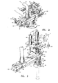
- the dust conveying and collecting system 50 includes an improved structure which is a generally tubular enclosure 52 referred to herein with regard to several embodiments as a material conveying or lifting head as opposed to the so called hoods of prior art dust collection systems.
- the head 52 is adapted to be disposed around the drillhole 35 at the ground surface 37 to provide a conveying passageway for all of the drill cuttings emanating from the drillhole.
- the head 52 has an interior flow passageway not substantially larger in flow area than the drillhole 35. The proportions of the head 52 as well as other embodiments disclosed will be discussed in further detail herein.
- the head 52 comprises a cylindrical hollow member having a radially outwardly projecting lower flange 54 adapted to be in substantially fluid tight engagement with the ground surface.
- the head 52 is telescopingly interfitted in a stationary section 56 which depends vertically from a generally hollow box-like enclosure 58 having an interior chamber 60 for receiving the drill cuttings and bailing air emanating from the drillhole 35.
- the head 52 is adapted to be slidably disposed within the vertically depending section 56 in close fitting relationship thereto.
- the head 52 is provided with mechanism for extending and retracting the head with respect to the deck plate 38, which mechanism includes a pair of spaced apart flexible cables 61 which are suitably connected to the flange 54, are reaved over sheaves 6.2 mounted on the exterior of the enclosure 58 and are adapted to be wound on a rotatable shaft 64.
- the shaft 64 is - suitably rotatably mounted on spaced apart frame members 66 which are themselves mounted on the lower side of the deck plate 38.
- the shaft 64 is rotatably driven by a drive mechanism 68 which includes a hydraulic motor and suitable gearing to provide for raising and lowering the head 52 by rotation of the shaft 64 to wind the cables 61 onto and off of- the shaft, respectively.
- the head 52 may be controlled to be in positive engagement with the ground surface 37 during drilling operations regardless of variations in the height of the deck plate 38 from the ground surface.
- the head 52 is preferably formed to have an inner diameter large enough to permit the passage of the drill bit through the head and up through an opening in the deck plate 38 which supports the bushing 40.
- the bushing 40 is adapted to fit into a supporting collar 41 which may be removably mounted on the deck plate.
- the bushing 40 is adapted to be removably fitted in the collar 41 and to have a bore diameter only sightly larger than the diameter of the drill stem 32 to prevent the flow of drill cuttings and bailing air upward onto the deck of the rig 20.
- the dust conveying and collecting system 50 includes an elongated enclosure 70 forming a conveying duct for the flow stream of bailing air and drill cuttings flowing through the interior 60 of the enclosure 58.
- the enclosure 70 is mounted adjacent to and may be considered to be a part of the enclosure 58.
- the enclosure 70 comprises an elongated rectangular duct having an interior flow chamber 71 which is partly defined by a top wall 73, and spaced apart sidewalls 75 and 77 and which are disposed closely adjacent to the opposite longitudinal sides of an endless conveyor belt 72 mounted on suitable spaced apart drive shafts 74 and 76.
- the shaft 76 may be adjustably mounted on the enclosure 70 by suitable tension adjusting mechanism 78.
- the drive shaft 74 is adapted to be rotatably driven by a hydraulic motor 80 to provide for driving the belt 72 in a direction to convey coarse drill cuttings that fall thereon along the enclosure 70 and out through a hinged door 82 disposed at one end of the enclosure and normally engaged with or spaced closely adjacent to the end of the belt 72.
- the door 82 is adapted to be forced open only when a sufficient amount of material is lodged against the door by the belt 72 and by a momentary reduction of the pressure differential between atmosphere and the chamber 71.
- the door 82 is normally biased in the closed position by the abovementioned pressure differential.
- the door 82 may be characterized as a resilient member made of sheet rubber, for example, which may be yieldably deflected to the open position to allow material to exit the enclosure.
- the opposite end of the enclosure 70 includes a transverse end wall 79 spaced closely adjacent to the opposite end of the belt 72.
- a horizontal seal plate 81 is contiguous with the sidewalls 75 and 77 and extends longitudinally between the shafts 74 and 76 and the runs of the belt 72.
- the conveying and collection system 50 further includes a duct 86 which is connected to the enclosure 70 and to a dust collection and filter unit, generally designated by the numeral 88 in Figure 1, and which will be described in further detail herein.
- the dust collection and filter unit 88 is adapted to separate both coarse and fine dust particles entrained in the bailing air flow stream and which have not been separated from the flow stream in the conveying enclosure 70. In accordance with the present invention it is contemplated that substantially all of the relatively coarse drill cuttings will be separated from the bailing air flow stream in the enclosure 70.
- particulate material required to be separated from the bailing air flow stream is likely to be of a wide variety of particle sizes and under certain operating conditions particles which may be considered relatively coarse will remain entrained in the bailing air flow as it exits the enclosure 70 and flows into the filter unit 88. Accordingly, as will be explained in further detail herein, the collection and filter unit 88 is adapted to separate the remaining relatively coarse particles from the bailing air flow stream as well as the very fine dust particles which are likely to remain entrained in the air even at relatively negligible flow velocities.
- the present invention contemplates an improved apparatus and method for conveying and collecting particulate material entrained in a bailing air flow stream emanating from a drillhole wherein the inertia- of the relatively coarse material and the velocity of the air stream entering an enclosure can be utilized to convey said coarse material to a point wherein it can be moved substantially away from the drillhole and wherein at the same time the finer material remaining entrained in the air stream may further be removed without interfering with the separation of the coarse material.
- the annular flow area of the interior of the head 52 is proportioned to be such that the air stream emanating from the drillhole maintains a substantial velocity until entering the enclosure 70, and the inertia of the particulate matter being conveyed out of the drillhole is sufficient to keep the coarse material as well as the fine material entrained in the air stream until it reaches the enclosure.
- a head for use with drill stems for drilling four inch diameter holes has a six inch diameter interior flow passage.
- the passageway 90 formed by the interior of the enclosure section 56 opens into the enclosure 58 at a point approximately even with the top of the conveyor belt 72.
- the relatively high velocity bailing air flow stream entering the interior 60 of the enclosure 58 impinges against the interior of the top. wall 59 of the enclosure and is redirected into the interior 71 of the elongated duct enclosure 70 without the loss of coarse particulate material back down through the passageway 90 into the drillhole.
- the top wall 59 be spaced from the flange 54, in the extended position of the hood, a distance approximately four to six times the nominal diameter of the drillhole so that a maximum flow stream velocity may be maintained to impinge the top wall and redirect the cuttings toward a lower pressure zone within the conveying enclosure. Thanks to the close fitting engagement of the flange 54 with the ground surface 37, the close interfit between head 52 and the depending duct section 56, the close fit of the bushing 40 around the drill stem 32 and the negative pressure maintained in the system there is virtually no loss of bailing air flow together with entrained particulate material out of the conveying system 50.
- the substantially horizontal impingement and deflecting surface formed by the top wall 59 will redirect the flow of the bailing air and the entrained material into the enclosure 70 without materially reducing the momentum of the coarse material due to the velocity of the continuous bailing air flow stream jetting from the drillhole through the passageway 90.
- a system for relatively large blast hole drills may require a suction blower or pump at the filter unit which has a nominal inlet volumetric capacity of only 1.0 to 1.5 times the . volumetric flow rate of system bailing air. This capacity is considerably less than is required by known prior art total collection systems.
- the improved conveying apparatus including the head 52 and the enclosures 58 and 70 together with the filter unit 88 of the present invention provides a total collection system which is operable to remove all of the particulate material from the vicinity of the drillhole and to extract substantially all of the particulate material regardless of particle size from the bailing air flow stream before the bailing air is exhausted from the system to atmosphere.
- the head illustrated in Figure 3 is generally designated by the numeral 100 and comprises a generally cylindrical tubular member 102 including a lower annular flange 104 to which is secured a frustoconical shaped collar 106 comprising a. secondary flexible seal suitably secured by a flange plate 107.
- The. collar 106 is preferably formed of a resilient 'elastomeric material which is deflectable to conform to any surface irregularities in the ground surface adjacent to the drillhole 35.
- the head 102 is mounted directly beneath and adjacent to one end of an elongated conveying duct or enclosure 108, similar to the enclosure 70 illustrated in Figure 2.
- the enclosure 108 includes an inlet portion having top and bottom walls 111 and 115, respectively.
- An open bottom portion of the enclosure 108 includes an endless conveyor belt 72 for conveying coarse drill cuttings to a point remote from the drillhole 35.
- the enclosure 108 also includes a hinged door 110 arranged similar to the door 82 at the end of the enclosure opposite the end to which the head 100 is attached.
- a seal plate 81 extends between the sidewalls of the enclosure 108 from the shaft 74 to the shaft 76 and terminates closely adjacent the periphery of each of the shafts to substantially prevent leakage air flow into or out of the interior 113 of the enclosure.
- the head 100 together with the coarse drill cuttings separation and conveying enclosure 108 is vertically extendable and retractable with respect to the deck plate 38 * by means of a pair of spaced apart pressure fluid cylinder and piston type actuators 112 mounted on the deck plate and having their respective piston rods 114 extending below the deck plate and connected to a supporting bracket 116 for the head and conveying enclosure assembly.
- the cylinder actuators 112 are of the double acting type and are adapted to be in communication with a source of compressed air such as the compressor 44 by way of a conduit 118 and a two-position four way valve 120.
- the valve 120 is adapted to supply pressure fluid to one end of each of the actuators 112 while venting the cylinder chamber at the opposite end and, upon being shifted from one position to another, to reverse the direction of fluid flow to and from the cylinders by way of the respective sets of conduits 122 and 124 shown schematically in Figure 3.
- the valve 120 is adapted to be normally in a position to provide pressure fluid through conduits 124 by way of conduit 118 to move the enclosure 1Q8 and the head 100 away from the drillhole 35 in a retracted position.
- the valve 120 is adapted to receive pressure air in a pilot actuator 121 by way of a conduit 126 which is in communication with the conduit 48 indicated schematically in Figure 3.
- the conduit 48 is adapted to conduct bailing air to the drill stem 32 in a manner as previously described.
- the normal arrangement of the bailing air control circuit includes a valve 132 which may be directly or remotely controlled by the drill operator to turn on and off the bailing air flow to the drill stem 32. Accordingly, with the circuit shown schematically in Figure 3 when the valve 132 is actuated to supply bailing air to the drill stem 32 the valve 120 is automatically actuated to conduct pressure air to the cylinders 112 to extend the head 100 and the enclosure 108 into the extended position with respect to the deck plate 38.
- the flange 107 and collar 106 will be biased into engagement with the ground around the drillhole 35 at any time bailing air is being conducted down the drill stem 32.
- the cylinders 112 are operable to automatically retract the head 100 and the enclosure 108 when bailing air has been shut off thereby assuring that when the drill rig is to be moved from one worksite to the other that the head is not inadvertently left extended and in engagement with the ground.
- the enclosure 108 is extensible and retractable with respect to the deck plate 38 it is provided with a suitable flexible seal element 109 to provide for the drill -stem 32 to extend through the enclosure but to prevent the escape of bailing' air and drill cuttings upward through the enclosure around the drill stem.
- the seal 109 may be of several types and might include a series of resilient deflectable circular sector shaped plate-like members which may be deflected to permit movement of the drill bit upward through the head and the enclosure when the drill stem is retracted completely out of the drillhole.
- the enclosure 108 also includes a substantially horizontal flow impingement and deflecting surface comprising the top . wall 111 of the enclosure 108.
- the velocity of the bailing air flow stream together with the momentum of the entrained drill will maintain the behavior of a free flowing jet until the flow stream impinges the deflecting surface formed by the wall 111 and is redirected longitudinally within the enclosure 108.
- the enlarged interior volume of the enclosure will result in a reduction in the flow velocity and the coarser drill cuttings will separate due to gravitational forces acting thereon.
- the cuttings will fall onto the conveyor 72 whereby they may be conveyed to a point remote from the drillhole for deposit on the ground surface or, if desired, collected for analysis or further processing.
- the collection and filter unit 88 which is illustrated in Figure 1 as being mounted on the side of the frame 22 of the drill rig 20, is illustrated in detail in Figures 4 through 6.
- the filter unit 88 includes a rectangular box-like housing, generally designated by the numeral 140, which is divided into a series of internal chambers by a plurality of interior partitions as will be described hereinbelow.
- the housing 140 includes a vertical rear wall 142 spaced from and parallel to a vertical front wall 144.
- the walls 142 and 144 are joined to spaced apart transverse vertical walls 146 and 148.
- the aforementioned walls are also contiguous with a horizontal top wall 150.
- the housing 140 includes a bailing air inlet flow chamber, generally designated by the numeral 152 in Figure 5, which.
- the bottom wall 156 extends downward from its point of intersection with the rear wall 142 towards the front wall 144 and extends longitudinally to be contiguous with the spaced apart end walls 146 and 148.
- the bottom wall 156 is also contiguous with opposed transverse sloping bottom wall portions 157 and 159., as shown in Figure 4.
- the chamber 152 is also delimited by a horizontally disposed interior partition 158 spaced from the top wall 150.
- a clean air outlet chamber 160 is formed by the top wall 150, the partition 158, the end walls 146, 148 and the vertical sidewalls 142 and 144.
- the inlet flow chamber 152 includes an enlarged separation chamber portion 162 which is also formed in part by a vertical transverse interior partition 164 contiguous with the partition 154, the bottom wall 156, the front wall 144 and the partition 158.
- the filter unit 88 further includes a plurality of side by side filter element chambers 170, 172, and 174 which, as shown in Figure 5, are formed separate from each other by spaced apart vertically disposed partitions 173 and 175.
- the partitions 173 and 175 extend vertically from the horizontal partition 158 to the bottom wall 156 thereby providing for the filter chambers 170, 172 and 174 to be separate from each other and in flow communication with each other only by way of separate openings in the partition 154 which will be described further hereinbelow.
- the number and arrangement of the filter element chambers may be varied. For example, only one or two chambers might be required for some systems.. Moreover, the chambers could be arranged on both sides .of the inlet chamber 152.
- Each of the chambers 170, 172 and 174 include vertically extending curved wall elements 180, 182 and 184, respectively, which extend from the underside of the horizontal partition 158 vertically downwardly and are coextensive with porous media type filter elements 186 disposed in each of the filter element chambers, as shown.
- the filter elements 186 may be of a known type which are constructed of a porous media such as a type of pleated paper through which the bailing air flow is conducted to filter out the very fine dust particles remaining entrained in the bailing air flow stream after gravity and inertial separation of the coarser particles is obtained.
- the filter elements 186 are suitably retained in the respective filter element chambers such as by elongated tie rods, not shown, which extend from the closed bottom 187 of each of the filter elements, as shown by way of example in Figure 4, to engagement with the horizontal partition 158.
- Each of the filter elements 186 has an outlet duct portion 188 extending into the chamber 160 for conducting substantially dust free air from the respective interiors of the filter elements into the chamber 160 and through an outlet opening 190 shown in Figure 4.
- the front vertical wall 144 includes a removable panel or door 192 which may be opened to gain access to each of the filter elements 186 for servicing, as needed.
- the filter unit 88 may be provided with suitable reverse air jet cleaning mechanism, generally designated by the numeral 196, and comprising a plurality of nozzles disposed in the chamber 160 and above each of the filter element outlet ducts 188.
- the reverse air jet cleaning mechanism is operable to periodically deliver brief pulses of compressed air through nozzles 198 in a direction generally opposite to the air flowing through the filter elements 186 to blow accumulated dust off the elements and into the respective filter element chambers.
- the substantial quantity of dust periodically blown off of the filter elements 186 will. settle in respective hopper portions 200, 202, and 204 of the chambers 170, 172 and 174 together with dust separated by the vertical movement of air flowing around the interior side of the curved walls 180, 182 and 184.
- hinged doors or flaps. 206 which function in a manner similar to a one way valve, will open to allow accumulated material to exit from the hopper portions. Thanks to the arrangement whereby each of the filter chambers 170, 172 and 174 are separate from each other the periodic reverse jet cleaning of each of the filter elements will not permit the dust blown off of one filter element to become entrained with an air flow stream flowing through an adjacent filter element. Accordingly, the cleaning of one or more of the filter elements 186 will not result in sudden loading of an adjacent filter element.
- the filter unit 88 is provided with further hopper means for collecting dust and drill cuttings which enter the chamber 152, said hopper means being formed in the lower portion of the chamber and generally designated by the numeral 208 as shown in Figure 6. Accordingly, drill cuttings entering the chamber 152 and which do not flow on into the separation chamber portion 162, or into the respective filter element chambers, settle into the hopper portion 208.
- the vertical partition 154 is provided with a plurality of hinged doors 210 which are operable to open to allow dust accumulated in the hopper portion 208 to flow into the respective chambers 170, 172 and 174 and into their respective hopper portions as indicated viewing Figures 4 and 6.
- the doors 210 may be rigid hinged members or preferably comprise flexible flaps which are- normally biased in the closed position but yield under the weight of accumulated material to open briefly and allow the material to slide down the interior of the sloping bottom wall 156 into the respective hoppers 200, 202 and 204 and on out of the filter unit 88 in due course.
- the separation chamber 162 also includes a hinged door 212 providing for periodic discharge of accumulated material from the. bottom of the separation chamber which comprises a hopper portion designated by the numeral 214.
- the filter unit 88 includes a suction blower or pump, generally designated by the numeral 216, which is mounted on the vertical end wall 146 at the opening 190 therein.
- the suction pump 216 illustrated is of the centrifugal type and includes an impeller 218 disposed within a housing or scroll 220 having an outlet duct 222 for discharging clean air to atmosphere.
- the impeller 218 is adapted to be rotatably driven by suitable motor means such as a hydraulic motor 224 connected to a source of hydraulic fluid such as the pump 46, shown schematically in Figure 1.
- a pneumatic or electric motor could be used.
- Hydraulic fluid may be supplied to the motor 224 by way of respective supply and return lines 226 and 228 which are suitably interconnected by a flow control valve 230 whereby the flow of fluid to the motor 224 may be controlled to vary the speed of the impeller 218.
- suction blower or pump means may be utilized in place of the illustrative pump 216 such as, for example, positive displacement helical screw or straight lobe type blowers or jet ejectors.
- valve 230 as well as the valve 132 shown in Figure 3 are preferably located on a suitable control panel in a control cab 43 on the rig 20 as shown in Figure 1.
- a two position valve 231 is interposed in the lines 226 and 228 and is operable upon commencing delivery of bailing air through line 48 to be actuated to start the pump 216.
- valve 132 When air is shut off by valve 132, for example, flow in line 226 is redirected to return line 228..
- dust laden air enters the filter unit 88 through an inlet opening 232 in the end wall 148 and which is in flow communication with the duct-86.
- Air entering the chamber 152 flows in a substantially linear jet stream toward the opposite end wall 146.
- the peripheral portions of the flow field of the jet stream entering the chamber through the opening 232 under go rapid reduction in velocity and flow through respective openings 234, 236 and 240 in the partition 154 and into the respective filter element chambers 170, 172 and 174. That portion of the flow stream which does not enter the respective filter chambers as described above flows into the separation chamber 162 and into the filter element chamber 170 through an opening 238 in the partition 164.
- the openings 234, 236, 238 and 240 are disposed in relation to the curved wall portions in the respective filter chambers as illustrated in Figure 5, are generally rectangular in shape and extend vertically substantially the length of the curved wall portions and the filter elements 186.
- the location of the openings 234, 236, 238 and 240 also impart a directional flow to the air entering the respective filter element chambers in a substantially curved flow path as guided also by the curved wall portions and the tendency for the air to flow inwardly through the respective filter elements in a somewhat vortical manner. Accordingly, the flow of air into the respective filter chambers provides for inertial separation of at least some of the entrained material, which material impinges the curved wall portions and falls downwardly into the respective hopper portions of the filter element chambers.
- a filter unit generally of the configuration described herein and illustrated in Figures 4, 5 and 6 is superior to prior art equipment which utilizes inertial as well as impingement type separation of particulate matter from an air flow stream.
- the inlet flow chamber 152 as illustrated in the drawings there is provided an inlet flow stream through the opening 232 of sufficient veiocity to keep relatively large or coarse particles which have not been previously separated from the flow stream entrained until they impinge the opposite end wall 146 or are diverted by air flowing into the separation chamber 162 and whereby these larger coarse particles do not enter the respective filter element chambers.
- the peripheral lower velocity portions of the flow stream which will maintain finer dust particles entrained therein may be diverted into. the respective filter element chambers through the openings 234, 236 and 240.
- the inlet flow chamber 152 and the separation chamber 162 are operative to provide inertial and gravity separation of a substantial portion of the relatively coarse material remaining entrained in the bailing air flow as it enters the filter unit. 88.
- This relatively coarse material either falls into the hopper portion 208 of the inlet chamber 152 or, if of sufficient energy to remain entrained in the moving air stream, impinges the end wall 146 and falls into the hopper portion 214 of the separation chamber 162.
- the relatively low velocity flow stream portions entering the respective filter element chambers undergo centrifugal and so called vortical flow to further inertially separate entrained material before the air impinges the porous media filter elements. Accordingly, the loading of the filter elements 186 is substantially reduced as compared with prior art filtration units which employ impingement or porous media flow through type filter elements.
- the improved preliminary separation of particulate material from the air flow stream entering the filter unit 88 before it reaches the filter elements 186 allows a substantial increase in the volumetric capacity per unit of area of the filter media of the elements 186 as compared with prior art filter units.
- the air flow passing through the respective filter element chambers 170, 172 and 174 flows through the curved flow path indicated between the filter elements and the curved wall. adjacent thereto and after passing through the respective filter elements flows into the outlet duct 160 and exits the filter unit 88 through the opening 190 and the suction pump 216 as substantially dust free air.
- the arrangement of the separate filter element chambers 170, 172 and 174 disposed side by side and adjacent to the elongated inlet chamber 152 together with the separation chamber 162 substantially eliminates any currents within the filter unit 88 which tend to keep particulate material entrained in the flow stream or re-entrain material which has already been separated.
- the separate filter element chambers for each of the porous media filter elements 186, which are back-flushable by the air jet cleaning mechanism, also substantially improves the performance of the filter elements since there is no cross flow of dust laden air from an element which is being cleaned to an element which is receiving air flow in the normal course of operation.
- the total power required for the conveying and collection system of the present invention is indicated to be substantially less than systems heretofore known.
- a suction pump such as the pump 216 in combination with a system in accordance with the present invention may' be required to have an inlet volumetric capacity of approximately only 1.0 to 1.5 times the volumetric flow rate of bailing air being conducted down the drill stem. This is considerably less than the suction blower or pump requirements of prior art systems.
- blower There are several factors which contribute to this low volumetric capacity requirement of the blower including the improved lifting head invention which forms a positive seal with the earth's surface adjacent to the drillhole, and the unique mechanical conveying system which is particularly useful in operation of the system with relatively large drill rigs.
- the volume of drill cuttings normally produced by relatively large drills would require substantial amounts of power to provide conveyance of all of the drill cuttings away from the drillhole if pneumatic conveying was totally relied on for that function.
- the improved filter unit 88 of the present invention more effectively utilizes the flow characteristics - of a moving air stream having particulate matter entrained therein whereby inertial and gravity separation of material from the flow is maximized and the impingement type filter elements are presented with bailing air flow which has a substantially reduced amount of entrained particulate matter.
- the overall arrangement of the components of the filter unit 88 are so advantageous that the amount of filter area for the impingement type filter element 186 for a given volumetric flow rate of bailing air through the unit may be reduced as compared with prior art systems.
- the provision of the separate filter element chambers having the substantially arcuate wall portions surrounding their respective filter elements provides for improved separation of material from the flow stream before it actually impinges the filter elements and further prevents any cross flow of dust from one filter element to another during reverse jet cleaning of the respective elements.
- FIG. 7 and 8 of the drawings there is illustrated a further alternate embodiment of a drill cuttings conveying and collecting head in accordance with the present invention.
- the ground surface at the site of the drillhole is uneven or not substantially parallel to the deck plate of the drilling rig. This may be due to uneven terrain at the immediate site of the drillhole with respect to the terrain that the rig is sitting on or, in some instances, it is desired to drill angle or slant holes.
- Certain drilling rigs are adapted to operate with their mast or feed beams partially reclined for drilling such holes and accordingly, the deck plate is not parallel to the ground surface.
- a dust conveying and lifting head generally designated by the numeral 250, which is adapted to be in substantial sealing engagement with the ground surface 37 under conditions where the ground surface may not be parallel to the deck plate 38 as well as when the rig is operated to drill angle holes or the like.
- the head 250 is adapted to be connected to a conveying duct 252 similar to the. duct or enclosure 108 but fixed to the deck plate 38.
- the head 250 includes a resilient, generally frustoconical skirt portion 254 which is adapted to be in forcible engagement with the ground surface 37 and is suitably secured to a substantially circular support plate 256 by a plurality of threaded fasteners 258.
- the fasteners 258 also secure an annular support or sealing flange 260 engaged with the skirt 254 as shown by the detailed broken portion of Figure 7.
- the skirt 254 is shown just in contact with the ground surface. In normal operation the skirt would be deformed to the position shown for the skirt of the head .illustrated in Figure 13, so that the sealing flange 260 would be engaged also with the surface 37.
- the head 250 includes a telescoping portion comprising an enclosure formed by a spirally coiled flat metal band 262 which is relatively tightly coiled to form a continuous duct.
- the band 262 is connected at its lower end to an annular collar 264 which is suitably secured in assembly with the support plate 256 and the skirt 254 as shown.
- the upper end of the telescoping spiral band 262 is suitably, secured to a cylindrical housing member 266 mounted on the underside of the duct 252.
- the head 250 is operable to be extended into the ground engaging position, illustrated by the solid lines in Figure 7, by an extensible pressure fluid cylinder actuator 268 similar to the actuators 112 illustrated in Figure 3.
- the actuator 268 may, for example, be interconnected with the source of compressed air by way of the conduits 122 and 124 in place of the cylinders 112 of Figure 3.
- the actuator 268 includes a piston rod 270 which is connected to a substantially U-shaped yoke member, generally designated by the numeral 272, having a base portion 274 and a pair of parallel projecting legs 276.
- the legs 276 are pivotally connected to the support plate 256 at their respective distal ends by means of pivot pins 278, as illustrated in Figures 7 and 8.
- the distal end 280 of the piston rod 270 is disposed in a cooperating slot 281 in the base portion 274 of the yoke member 272 and is retained in pivotal connection therewith by a pivot pin 282. Accordingly, the yoke member 272 provides. a gimbal or universal type interconnection between the base plate 256 of the head and the actuator 268 whereby the skirt 254 will be adaptable to engage the ground surface 37 regardless of its angularity with respect to the deck plate 38, that is, within the limits of range of movement of the gimbal type connection between the actuator and the head.
- the skirt 254 will be biased into engagement with the ground surface 37 in the same manner that the head 100 is continually biased as long as bailing air flow is being conducted the drillhole 35.
- the coiled metal band 262 is proportioned such that the helical convolutions 263 of the band overlap each other slightly even in the greatest extended position of the band and also are substantially contiguous with one another to prevent any leakage of bailing air into or out of the interior of the head.
- the band 262 as well as the skirt 254 are subject to severe abrasion due to the high velocity flow stream of bailing air and the abrasive drill cuttings entrained therewith. Accordingly, the tubular band 262 and the skirt 254 may be replaced as needed.
- the lifting head 250 may be used in conjunction with the conveying duct enclosure 70 as well as the duct 252 and, in fact, the duct 252 may include a mechanical conveying mechanism similar to the mechanism disposed in the enclosures 70 and 108.
- two. cylinders similar to the cylinder 268 may be used in place of a single cylinder, if necessary, wherein the distal ends of the respective piston rods would be connected at spaced apart points on the base portion 274 of the yoke member 272.
- FIG. 9 Another alternate embodiment of a dust conveying and collection system in accordance - with the present invention is illustrated in Figures 9 through 13 of the drawings.
- an earth drilling rig generally designated by the numeral 300, which is of the percussion type as opposed to the rotary type described hereinabove in connection with the previous drawing figures.
- the drilling rig 300 includes a crawler type undercarriage 302 on which may be mounted a mast or feed beam 304 adapted to be positioned in a wide variety of drilling attitudes for drilling vertical holes in the earth's surface 37 as well as holes at various angles.
- the drilling rig 300 includes a pressure fluid operated percussion drill hammer 306 adapted to deliver percussive blows to a drill stem 308.
- the drill stem 308 is normally made up of elongated hollow rod-like members 310 which are provided with external threads, not shown, on each end and are connected end to end by internally threaded coupling members 312 as illustrated in Figures 9, 10 and 12.
- the drilling rig 300 is also operable to provide bailing air to be conducted down through a passageway within the drill 306 and the drill stem 308 and through an internal bore in the respective drill rod members 310 from a source either on board the rig 300 or connected thereto.
- the drill rig 300 is adapted for drilling holes of nominal diameters up to 5 inches and does not produce the quantity of cuttings associated with operation of the larger rotary type drills. Accordingly, the drill rig 300 is provided with a dust conveying or lifting head generally designated by the numeral 316, which is adapted to be mounted on the base of the mast 304, as shown in Figure 10, by means of suitable bracket 317.
- the head 316 includes a frustoconical shaped annular skirt portion 318 formed of a suitable resilient material and which is suitably fastened to a lower flange 320 of a vertically disposed tubular duct portion 322.
- the head 316 also includes a conveying duct portion 324 integrally formed with the duct portion 322 and disposed at an upwardly inclined angle with respect to the longitudinal axis of the duct portion 322 which is coincident with the drilling axis of the drill stem 308.
- the upper external surface of the head 316 includes a substantially flat portion and is provided with a pair of spaced apart upstanding flanges 326 and 328, as shown in Figures 10, 11 and 13, forming a guide channel for a pair of movable gate members 330 and 332.
- the gate members 330 and 332 are adapted to form a relatively tight closure around the drill stem 308 during normal drilling operations, but are movable away from the drilling axis, as required, to permit movement of the couplings 312 through the head during drilling operations or when the drill stem is being removed from the drillhole 307.
- the head 316 includes an opening 333 formed in the top of the duct portion 324 and which is substantially of the same diameter as the interior of the vertical tubular portion 322.
- the opening 333 may be smaller than the interior of the duct portion 322 but must be sufficiently large to . permit the movement of the coupling 312 and the drill bit 309 through the head. Accordingly, in the closed position of the movable gate members 330 and 332 a flow deflecting surface is provided over the opening 333 to prevent the bailing air flow stream emanating from the drillhole 307 from exiting the head through the opening 333.
- the gate member 330 is characterized as an elongated generally rectangular plate having a longitudinally formed slot 336 opening to one end of the plate and of a width slightly larger than the maximum diameter of the drill rod members 310.
- the end of the gate member 330 opposite the end in which the slot 336 is formed includes a laterally projecting boss 331 which is connected to the piston rod 338 of a pressure fluid cylinder actuator 340.
- the opposite end of the actuator 340 is suitably secured to a bracket portion 342 of the head 316. Accordingly, the member 330 is operable to be actuated by the cylinder actuator 340 to move to the position illustrated by the dotted lines in Figure 11 to retract away from the opening 333.
- the member 332 includes a pair of laterally projecting trunnion portions 344 which are adapted to be disposed in vertically elongated slots 346 formed in the respective flanges 326 and 328.
- the member 332 also includes an elongated slot 348 having a width essentially the same as. the slot 336 and also opening to one end of the member 332.
- the opposite end of the member 332 includes an integral enlargement 350 acting as a counterweight which tends to pivot the member 332 into the position indicated by the dashed lines in. Figure 12.
- the gate member 330 In the closed position of the members 330 and 332 illustrated-in Figures 10, 11, and 12 the gate member 330 is disposed under the gate member 332 and forces the member 332 into the position shown in Figure 12 overlaying the slot 336.
- the slot 348 overlies the solid portion of the member 330 so that only a substantially circular opening is presented for movement of the drill stem 308 through the head.
- the tubular portion 322 includes a vertically upwardly projecting tang 356 which is proportioned to be disposed in the slot 336 to substantially prevent the flow of bailing air out of the head 316 through the slot.
- the actuator 340 may be energized by the drill operator, who is normally standing at an operator's control panel 301, as shown in Figure 9, and is in full view of the drill stem and the head.
- the member 330. is actuated to slide away from the drill stem 308 the member 332 pivots into a substantially vertical position, indicated by the dashed lines in Figure 12, to provide sufficient clearance to permit movement of coupling members and/or the drill bit through the head 316.
- the coupling formed by the trunnions 344 and the elongated slots 346 provides for the gate members 330 and 332 to move freely even if a considerable amount of drill cuttings become lodged between the members.
- the coupling formed by the vertically disposed slots 346 permits the gate member 332 to rest against the transverse end wall or striker plate 352 to relieve the vibratory drilling forces from being imposed on, the trunnions 344.
- the actuator 340 may then be energized to slide the member 330 back toward the striker plate 352 whereby the member 332 will be engaged by the distal end of the member 330 and pivoted back to the closed position illustrated in Figures 10, 11, and 12.
- the gate members 330 and 332 form a major part of a flow deflecting surface in the interior flow channel 325 of the head 316 to deflect the flow of bailing air laden with drill cuttings and dust upwardly through the tubular duct portion 324 into a coarse drill cuttings separation enclosure generally designated by the numeral 360.
- the enclosure 360 includes an enlarged interior chamber 362 having an inlet opening 364 and a bailing. air outlet opening 366 preferably formed in a top wall 367 of the enclosure.
- the chamber 362 includes a hopper portion 368 for collecting relatively coarse drill cuttings that are separated from the bailing air flow stream as it enters the chamber 362 and undergoes a substantial change in flow direction caused by the angularly disposed deflector plate 370.
- the deflector plate 370 is formed to be -substantially perpendicular to the direction of flow of the bailing air flow stream as it enters the chamber 362 from the head 316.
- the enlarged volume of the chamber 362 together with the presence of the deflector plate 370 provides, for separation of a substantial portion of the particulate material entrained in the bailing air flow due to a change of direction of the flow stream as well as a reduction in velocity resulting from the enlarged volumetric capacity of the chamber 362 as compared with the passageway 325.
- the enclosure 360 includes a door 372 which is operable to periodically swing open to allow cuttings collecting within the hopper portion 368 to flow out of the enclosure 360 onto the ground at a point remote from the drillhole 307, as illustrated in Figure 9.
- the door 372 is normally biased in a closed position by the pressure differential within the chamber 362.
- the door 372 may be made of an elastic material similar to the drill cuttings discharge doors used on the enclosure 70 and 108 and the dust collection and filter unit
- the bailing air flow stream exiting the enclosure 360 through the opening 366 is conducted by way of a duct 374 to a collection and filter unit, generally designated by the numeral 376, as shown in Figure 9.
- the filter unit 376 is preferably of a type similar to the filter unit 88 and may be sized according to the maximum air flow requirements of percussion type drill rigs, which flow requirements are generally less than the relatively larger rotary type rigs. Accordingly, the filter unit 376 may utilize either smaller separation and filter element chambers, for example, or a fewer number of filter element chambers.
- the filter unit 376 is also provided with a suction blower or pump, generally designated by the numeral 380 in Figure 9, which may be similar to the pump 216 illustrated in Figure 4.
- the suction pump 380 is also preferably provided with means for varying the volumetric capacity of the pump to provide for a negative pressure throughout the flow path of the bailing air flow stream at any point above the ground surface so that any leakage flow around the skirt 318, the gate members 330 and 332 or through the opening 371 in the enclosure 360 will be from the ambient exterior atmosphere into the bailing air flow stream.
- Figure 13 illustrates the operating position of the lifting head 316, which position is typical of the preferred operating position for all of the lifting head embodiments disclosed herein.
- the head 31 b in operation the head 31 b . is forcibly engaged with the surface 37 such that a substantially rigid annular sealing flange 319 suitably fastens the flexible collar 318 to the flange 320 by a plurality of threaded fasteners, not shown.
- the flange 319 is in forcible sealing engagement with the earth and a secondary seal around the drillhole 307. is provided by the flexible collar or skirt 318.
- a material conveying or lifting head in accordance with the present invention be provided with an interior passageway along the duct portion 322, for example, and designated by the numeral 323 which is sufficiently larger than the diameter of the drillhole 307 to provide substantially unrestricted flow of the stream of bailing air and drill cuttings emanating from the hole.
- the flow passage 323- not be enlarged to the extent that would cause a reduction in velocity of the flow stream or allow the drill cuttings to separate within the duct portion 322 and collect around the periphery of the drillhole as is characteristic of most prior art drill cuttings conveying enclosures or hoods.
- Another problem in the art of drilling which determines to some extent the diameter or peripheral dimensions of the passage 323 pertains to the tendency for the bailing air flow stream to erode the sides of the drillhole 307 near the intersection with the earth's surface. This eroded portion of the drillhole 307 is indicated by the numeral 309 in Figure 13. It is desirable to minimize the erosion of the drillhole at the earth's surface.
- the transverse diametral dimension of the flow passage 323 be approximately 2 inches greater than the nominal hole diameter for holes in the range of 3 to 4 inches in diameter. It is also preferable that the diameter of the flange 319 be approximately twice the diameter of the flow passage 323. If the diameter of the sealing flange 319 is not sufficient, erosion of the drillhole under the flange may occur and cause the hole to break out from under the flange. Where space permits the skirt 318 is proportioned to have an extended or displaced outer diameter of approximately 3 times the hole diameter, although this is not as critical as the provision of an adequate sealing flange 319.
- a lifting head in accordance with the present invention is to be used in substantially soft earth material such as sand or soft clay, as typified by the design of the lifting head 52, the interior flow passage of the head is proportioned in accordance with the aforementioned parameters with respect to drillhole size, and the diameter of the flange 54, for example, would also be approximately 3 times nominal hole diameter.
- the important factors in determining the cross sectional flow area of the interior passageways of a lifting head according to the present invention primarily deal with proportioning the passageways such that the flow of bailing air and entrained cuttings is not impeded or choked, which will result in plugging of the flow path, but at the same time is only sufficiently larger than the drillhole as to permit this relatively unrestricted flow while maintaining substantial velocity of the flow stream.
- the lifting head illustrated in Figure 14 is generally designated by the numeral 400 and includes a substantially vertical tubular portion 402 having a lower annular flange 404 to which is secured a flexible skirt or secondary sealing member 406.
- the skirt 406 is secured to the flange 404 by a lower rigid sealing flange 408 in a suitable manner.
- the lifting head 400 also includes a conveying duct portion 410 in communication with the tubular duct portion 402 and projecting upwardly at an angle of approximately 45 degrees with respect to the axis of the portion 402.
- the head 400 further includes an upper transverse end wall 412 having a bore 414 proportioned large enough to permit the drill stem 32 and bit 34' to be withdrawn through the head.
- the bore 414 is suitably sealed during drilling operations by the provision of a relatively heavy metal collar 416 disposed around the drill stem 32 in close fitting relationship thereto and normally resting on a surface 420 of the upper transverse wall portion 412.
- the collar 416 is provided to be of suitable weight such that under all drilling conditions the bailing air flow stream emanating from the drillhole 35 will not blow out through the bore 414. However, under normal operating conditions the differential pressure within the lifting head 400 would not provide any tendency for the collar 416 to be lifted off of the surface 420.
- Figure 14 also illustrates a modified embodiment of a coarse drill cuttings separation enclosure generally designated by the numeral 430 and which is suitably connected to the duct portion 410.
- the enclosure 430 is similar in some respects to the enclosure 360 and is characterized in having . an enlarged interior chamber 442 in communication with the flow passage within the duct portion 410.
- the chamber 442 includes. a vertically depending portion 444 forming a hopper. for collection of coarse drill cuttings and the like.
- the enclosure- 430 includes a door 446 suitably fastened to a sloping bottom wall portion 447 of the enclosure.
- the door 446 is preferably made of a resilient material and is normally biased in the closed position but under the urging of the weight of material collecting in the hopper portion 444 is operable to open to discharge material from the chamber 442. In operation with the filter unit 88 or a similar unit the door 446 is also held closed by the differential pressure between the chamber 442 and the exterior of the enclosure 430.
- the enclosure 430 also includes a door 448 forming a portion of a sloping top wall and a substantially vertical sidewall of the enclosure and which is provided primarily for clean out operations, if needed.
- the enclosure 430 further includes an arm 450 of the chamber 442 which is laterally spaced from the longitudinal axis of the duct portion 410 and is in communication with an outlet duct 452 leading to a filter unit, not shown, such as the filter unit 88.
- the arrangement of the chamber 442 including the hopper portion 444 and the laterally spaced arm 450 provides for superior separation of the coarse drill cuttings from the flow stream being conducted through the duct portion 410.
- As the flow enters the chamber 442 it impinges the top and sidewalls of the enclosure including the door 448 and undergoes change in direction which separates substantially all of the relatively coarse drill cuttings which collect in the hopper portion 444.
- the heaviest cuttings may separate primarily due to gravity while intermediate size cuttings impinge the walls of the enclosure and are deflected into the hopper portion 444.
- the head 400 includes a vertically extending member 454 which may be suitably connected to a piston and cylinder type actuator for extending the head into engagement with the ground surface 37 as shown, and in a manner similar to the manner in which the heads 262 and 100 are mounted.
- the head 400 is adapted to operate with substantially tubular drill strings such as the drill stem 32 although it could be adapted to operate with percussion type drill stems also.
- FIG. 15 a further embodiment of a conveying head and apparatus for separating relatively coarse drill cuttings is illustrated mounted on the deck plate 38.
- the apparatus illustrated in Figure 15 includes a conveying head - generally designated by the numeral 500 including a vertically depending tubular portion 502 in which is telescopingly fitted a tubular member 504 adapted to be slidably moved between an extended position in engagement with the ground surface and a retracted position for transport of the drill rig.
- the head member 504 includes a lower annular flange 506 and a flexible skirt or seal member 508 fixed thereto in a manner similar to the arrangement of the head 100 illustrated in Figure 3.
- the extensible and retractable head member 504 is suitably connected to a U-shaped bracket 510 as shown and having its base portion connected to the distal end of a piston rod 512 of a pressure fluid cylinder actuator 514 mounted on the deck plate 38.
- the actuator 514 is adapted to be connected to the conduits 122 and 124 in a manner similar to the arrangement illustrated in Figure 3. Accordingly the head member 504 may be extended and retracted in accordance with the provision of bailing air to the drill stem 32.
- the arrangement illustrated in. Figure 15 includes an enclosure 520 suitably mounted on the underside of the deck plate 38 and providing an interior chamber for receiving the bailing air flow stream flowing upwardly through the head 500.
- the enclosure 520 includes an elongated duct portion 522 having an interior chamber 524 for receiving the bailing air flow stream together with substantially all of the entrained drill cuttings.
- the lower portion of the duct 522 is formed as a. trough in which is rotatably mounted an elongated helical screw type conveyor 526 mounted on suitable bearings at each end of the duct and adapted to be rotated by a pressure fluid motor 528 mounted on the duct and operably connected to the conveyor screw.
- the duct 522 also includes a hopper portion, designated by the numeral 530, and disposed at a point remote from the drillhole for discharging cuttings conveyed by the screw 526 from the enclosure.
- the hopper portion 530 is also provided with.
- a flexible hinged door 532 which is operable to open under the weight of cuttings being discharged into the hopper portion when the pressure differential between the interior chamber 524 and the ambient atmosphere is reduced sufficiently.
- the duct 522 is also adapted to be in flow communication with the duct 86 for conducting the bailing air flow stream to the fine drill cuttings collection and separation unit.
- the bailing air flow stream emanating from the drillhole will be conveyed upwardly into the enclosure portion 520 and redirected into the duct 522 through the opening 534 whereby the enlarged volume of the chamber 524 will permit a reduction in the flow velocity sufficient to permit separation of relatively coarse drill cuttings.
- the separated cuttings are conveniently conveyed along the duct 522 by the conveyor screw 526 to the hopper 530 for final discharge from the apparatus in accordance with the teachings of the present invention.
- the arrangement illustrated in Figure 15 is advantageous in that the screw type conveyor may be conveniently disposed within a duct or other suitable enclosure with minimum requirements for sealing the conveying mechanism from ambient atmosphere. Accordingly, there is virtually no leakage of atmospheric air into the bailing air flow stream and, moreover, the screw type conveyor is an efficient and mechanically uncomplicated means for conveying coarse drill cuttings separated from the flow stream to a final discharge point remote from the drillhole.
- a preferred mode of operation of the total conveying and collection system of the present invention comprises the steps of extending the lifting head into sealing engagement with the ground surface adjacent the drillhole prior to operation of the drilling rig to commence drilling. Extension of the head as well as start up of the suction pump on the filter unit such as the pump 216, for example, could be coincident with. the provision of bailing air down through the .drill stem into the drillhole in accordance with the control system described herein.
- the speed of the motor 224 would be either preset in accordance with known bailing air flow requirements or controlled by the drill rig operator to maintain a flow rate which would provide a negative pressure within the passageways of the conveying and collection system.
- the reverse jet cleaning system would be set to provide periodic pulses of reverse jet cleaning air to the filter elements, which pulses would provide momentary pressure increases in the system sufficient to allow the discharge doors on the separation chambers to momentarily open to discharge collected material.
- the change in pressure within the system to allow the doors to open is so brief that as the coarse cuttings are being discharged from, for example, the chamber 71 or the hoppers 368, 444 or 530 that air flow is still substantially from the exterior of the enclosures into the enclosures. This action provides a further scrubbing or cleaning of fine dust from the coarse particles and prevents dust from emanating from the coarse material collection chambers.
- a conveying and collection system for particulate material such as drill cuttings or the like in accordance with the teachings of the present invention is operable to separate approximately 75 to 85 percent of the total material ejected from the drillhole in the coarse drill cuttings separation enclosures such as the enclosure 70, 108, 360, 430 or 520.
- prior art total collection systems are required to operate with four to six times the bailing air flow volume being conducted down through the drill stem as the total air flow which must be handled by the collection and filtration unit.
- the total air flow handled by the collection and filter unit is less than prior art systems, the suction blower requirements are reduced, and the size and/or number of impingement type filters is less than heretofore. required.
- the present invention significantly improves the overall process of conveying and collecting substantially the full range of particulate material that is normally generated in earth drilling operations and wherein such material is evacuated from the drillhole by a gaseous medium such as compressed air.
- a gaseous medium such as compressed air.
- the present invention is particularly adapted to utilize the energy of a bailing air flow stream to convey the drill cuttings beyond the entrance to the drillhole through an improyed conyeying head disposed around the drillhole entrance and sized to maintain the bailing air flow velocity and energy level as high as possible to convey the cuttings away from the immediate vicinity of the drillhole.
- apparatus for collection of particulate material from a substantially continuous air flow stream comprising:
- the housing may include a plurality of filter element chambers formed therein, each of said chambers having a filter element disposed-therein and inlet openings into each of said filter element chambers, said inlet openings being disposed in-said sidewall portion in spaced apart relationship one with respect to the other and between said end wall portion and said opening into said inlet chamber.
- the housing includes a portion defining a separator chamber disposed at one end of said inlet chamber for collecting relatively coarse material from said flow stream impinging said end wall portion, and may also include common wall means defining, in part, said separator chamber and said filter element chamber, and a second opening into said filter element chamber formed in said common wall means.
- the filter element chamber may include wall means disposed therein and adapted to cause air flowing into said filter element chamber to follow a substantially curved flow path along at least a portion of said wall-means before flowing through said filter element.
- First hopper means may be provided for receiving particulate material separated from said flow stream in said inlet chamber,.and in this case each filter element chamber may include separate hopper means for receiving particulate material from respective ones of said filter'element chambers.
- the first hopper means includes a vertically sloping bottom wall, said bottom wall forming a part of said separate hopper-means, a vertical wall separating said first hopper means from said separate hopper means, and a door in said vertical wall operable to open to discharge particulate material from said first hopper means into at least one of said separate hopper means.
- Preferably means are connected to the head for moving the head between an extended position toward the ground surface and a retracted position.
- the head may comprise a first portion including said flow deflecting surface means, and a second portion adapted to be extended and retracted with respect to said first portion and connected to said means for moving said head, and said.
- head moving means may include actuator means, and means interconnecting said actuator means and said head operable to provide for movement of said head with respect to said actuator means.
- the interconnecting-means preferably comprises a bracket pivotally connected to said head and to said actuator means to provide movement of said head about two-mutually perpendicular pivot axes.
- the head preferably includes a lower peripheral flange portion including means forming the said peripheral edge, and a-member, such as a spirally-coiled flat-sided band, forming an extensible tubular enclosure for conducting said flow stream.
- the said enclosure means may include flow-deflecting surface means interposed in the flow path of said flow stream for deflecting drill cuttings entering said enclosure, and a hopper portion for receiving coarse drill cuttings separated from said flow stream by impingement against said flow deflecting surface-means.
- the enclosure is preferably connected to said head by elongated conveying duct means in flow receiving communication with said passage, said conveying duct means being adapted to support said enclosure at a point remote from said drillhole, and said means for discharging said coarse drill cuttings preferably includes door means on said enclosure operable to open periodically for discharging drill cuttings from said enclosure at a point remote from said drillhole.
- the head may have flexible skirt means disposed around said flange and adapted to be in sealing engagement with the ground surface around said drillhole.
- the flange may form an annular plate engageable with the earth's surface around said drillhole for preventing the erosion of the mouth of said drillhole by said bailing air flow stream.
- the first member includes a plate slidably disposed on said head for movement between open and closed positions, and said head includes means for mounting said second member in such a way as to permit said second member to move to an open position enlarging the opening in said head in response to movement of said first member away from said drill stem;
Landscapes
- Engineering & Computer Science (AREA)
- Life Sciences & Earth Sciences (AREA)
- Geology (AREA)
- Mining & Mineral Resources (AREA)
- Mechanical Engineering (AREA)
- Physics & Mathematics (AREA)
- Environmental & Geological Engineering (AREA)
- Fluid Mechanics (AREA)
- General Life Sciences & Earth Sciences (AREA)
- Geochemistry & Mineralogy (AREA)
- Chemical & Material Sciences (AREA)
- Chemical Kinetics & Catalysis (AREA)
- Earth Drilling (AREA)
- Filtering Of Dispersed Particles In Gases (AREA)
- Refuse Collection And Transfer (AREA)
- Sampling And Sample Adjustment (AREA)
- Drilling And Exploitation, And Mining Machines And Methods (AREA)
- Auxiliary Methods And Devices For Loading And Unloading (AREA)
- Processing Of Stones Or Stones Resemblance Materials (AREA)
- Percussive Tools And Related Accessories (AREA)
Priority Applications (1)
| Application Number | Priority Date | Filing Date | Title |
|---|---|---|---|
| AT82300046T ATE19132T1 (de) | 1981-01-07 | 1982-01-06 | Vorrichtung zum staubsammeln und -abfuehren. |
Applications Claiming Priority (2)
| Application Number | Priority Date | Filing Date | Title |
|---|---|---|---|
| US06/223,036 US4434861A (en) | 1981-01-07 | 1981-01-07 | Dust conveying and collecting system and method |
| US223036 | 1981-01-07 |
Publications (3)
| Publication Number | Publication Date |
|---|---|
| EP0056014A2 true EP0056014A2 (fr) | 1982-07-14 |
| EP0056014A3 EP0056014A3 (en) | 1982-08-11 |
| EP0056014B1 EP0056014B1 (fr) | 1986-04-09 |
Family
ID=22834742
Family Applications (1)
| Application Number | Title | Priority Date | Filing Date |
|---|---|---|---|
| EP82300046A Expired EP0056014B1 (fr) | 1981-01-07 | 1982-01-06 | Dispositif pour le captage et le transport de poussières |
Country Status (7)
| Country | Link |
|---|---|
| US (4) | US4434861A (fr) |
| EP (1) | EP0056014B1 (fr) |
| AT (1) | ATE19132T1 (fr) |
| AU (1) | AU553520B2 (fr) |
| CA (2) | CA1181016A (fr) |
| DE (1) | DE3270329D1 (fr) |
| ZA (1) | ZA817437B (fr) |
Families Citing this family (62)
| Publication number | Priority date | Publication date | Assignee | Title |
|---|---|---|---|---|
| US4889196A (en) * | 1988-11-07 | 1989-12-26 | Johnston Vaughn R | Diverter apparatus |
| US5016717A (en) * | 1989-03-14 | 1991-05-21 | Aqua-Vac Locators, Inc. | Vacuum excavator |
| US5320188A (en) * | 1990-09-05 | 1994-06-14 | England J Richard | Underground mining system |
| US5191156A (en) * | 1992-04-14 | 1993-03-02 | The United States Of Americas As Represented By The United States Department Of Energy | Drill string enclosure |
| US5269386A (en) * | 1992-08-27 | 1993-12-14 | Ingersoll-Rand Company | Self positioning dust seal holder |
| SE9302741D0 (sv) * | 1993-08-25 | 1993-08-25 | Volvo Ab | Anordning för alstring av ljud i fordon |
| US5694716A (en) * | 1994-11-22 | 1997-12-09 | Bible; George R. | Root feeding device and associated root feeding method |
| US5730786A (en) * | 1995-06-07 | 1998-03-24 | Ceco Filters, Inc. | Multiple in-duct filter system |
| US6481507B1 (en) * | 1995-08-09 | 2002-11-19 | Paul Kromray, Jr. | Doweling hole drilling machine |
| US5860232A (en) * | 1995-12-06 | 1999-01-19 | Concept Engineering Group, Inc. | Mobile safe excavation system having a deflector plate and vacuum source |
| AUPN849596A0 (en) * | 1996-03-06 | 1996-03-28 | Dobson, Austin James | Drill discharge apparatus |
| US5795369A (en) * | 1996-03-06 | 1998-08-18 | Ceco Filters, Inc. | Fluted filter media for a fiber bed mist eliminator |
| US5718298A (en) * | 1996-04-10 | 1998-02-17 | Rusnak; Jerry A. | Separation system and method for separating the components of a drill bore exhaust mixture |
| US7469237B2 (en) * | 1996-05-02 | 2008-12-23 | Cooper David L | Method and apparatus for fractal computation |
| CA2226638A1 (fr) * | 1998-01-09 | 1999-07-09 | Canadian Air Drilling Services Limited | Separateur pour gaz, liquides et solides provenant d'un puits |
| US6216800B1 (en) | 1998-11-24 | 2001-04-17 | J. H. Fletcher & Co., Inc. | In-situ drilling system with dust collection and overload control |
| US6637522B2 (en) | 1998-11-24 | 2003-10-28 | J. H. Fletcher & Co., Inc. | Enhanced computer control of in-situ drilling system |
| US6095263A (en) * | 1998-12-23 | 2000-08-01 | Svedala Industries, Inc. | Drill rig operator cab viewport |
| US6182773B1 (en) * | 1999-01-10 | 2001-02-06 | Harnischfeger Technologies, Inc. | Blasthole drill having a drill pipe seal assembly |
| US6332308B1 (en) | 1999-06-04 | 2001-12-25 | Rodney Miller | Air filtration device for use with roof drill |
| CA2330416A1 (fr) * | 2000-01-27 | 2001-07-27 | Medallion Oil Company | Systeme de forage pneumatique et methode de retention et de separation des copeaux |
| AT410356B (de) * | 2000-05-17 | 2003-04-25 | Voest Alpine Bergtechnik | Einrichtung zum abdichten eines bohrloches und zum ausbringen von bohrklein bzw. gelöstem abbaumaterial |
| FI20001685A0 (fi) * | 2000-07-19 | 2000-07-19 | Tr Tech Int Oy | Mittausjärjestelmä ja menetelmä hiukkasnopeuden ja/tai hiukkasnopeusjakauman ja/tai hiukkaskoon ja/tai hiukkaskokojakauman mittaamiseksi |
| FI113796B (fi) * | 2000-10-24 | 2004-06-15 | Sandvik Tamrock Oy | Kallionporauslaite |
| FI20045197A0 (fi) * | 2004-05-31 | 2004-05-31 | Sandvik Tamrock Oy | Porasoijan imusuppilo ja aloitusohjain |
| US7073612B2 (en) * | 2004-06-01 | 2006-07-11 | Finchum Ray A | Surge device for air drilling |
| US7484322B2 (en) * | 2004-10-22 | 2009-02-03 | Mclaughlin Group, Inc. | Digging and backfill apparatus |
| US7753126B2 (en) * | 2005-11-26 | 2010-07-13 | Reddoch Sr Jeffrey A | Method and apparatus for vacuum collecting and gravity depositing drill cuttings |
| WO2007122528A1 (fr) * | 2006-04-21 | 2007-11-01 | Petrus Christiaan Gouws | Equipement auxiliaire destine a etre utilise avec un appareil de forage |
| ES2776923T3 (es) | 2006-07-04 | 2020-08-03 | Comacchio Int S A | Cabezal de perforación con nueva campana de protección |
| US7837050B2 (en) * | 2006-10-06 | 2010-11-23 | McLaughlin Group, Inc | Collection tank |
| US20080244859A1 (en) * | 2007-04-03 | 2008-10-09 | Charles Robert Maybury | Vacuum system with improved mobility |
| FI123739B (fi) * | 2007-04-04 | 2013-10-15 | Sandvik Mining & Constr Oy | Kallionporauslaitteen suojusrakenne melun vaimentamiseksi |
| US8002050B2 (en) | 2008-05-06 | 2011-08-23 | Frazier W Lynn | Completion technique and treatment of drilled solids |
| US8025111B2 (en) * | 2008-12-10 | 2011-09-27 | J.H. Fletcher & Co. | Agitator for a drill and related methods |
| US8261855B2 (en) * | 2009-11-11 | 2012-09-11 | Flanders Electric, Ltd. | Methods and systems for drilling boreholes |
| FI20105455A0 (fi) | 2010-04-26 | 2010-04-26 | Kari Lahtinen | Laite hydraulivasaraan |
| US9688492B2 (en) | 2011-03-10 | 2017-06-27 | Ksw Environmental, Llc | Method of reducing silicosis caused by inhalation of silica-containing proppant, such as silica sand and resin-coated silica sand, and apparatus therefor |
| DE102013000512A1 (de) * | 2012-02-18 | 2013-08-22 | Cft Gmbh Compact Filter Technic | Vorrichtung zum Trockenbohren mit Bohrkleinabsaugung |
| FI125722B (fi) | 2012-09-19 | 2016-01-29 | Erimek Oy | Näytteenottolaitteisto |
| WO2014065819A1 (fr) * | 2012-10-26 | 2014-05-01 | Donaldson Company, Inc. | Collecteurs de poussière avec un unique accès de service latéral et/ou systèmes de nettoyage à impulsion inversée pivotants |
| US9393657B2 (en) * | 2013-02-22 | 2016-07-19 | Hadley H. Caneer | Debris evacuator for cleaning a masonry bore |
| EP2886789B1 (fr) * | 2013-12-20 | 2019-02-27 | Sandvik Mining and Construction Oy | Support d'outil de forage et procédé d'amorçage de trou |
| CA2900101C (fr) | 2014-08-13 | 2023-01-03 | Harnischfeger Technologies, Inc. | Systeme de suppression automatique de la poussiere et methode |
| US20150167991A1 (en) * | 2015-02-27 | 2015-06-18 | Caterpillar Inc. | Dust containment assembly |
| FR3040893B1 (fr) * | 2015-09-11 | 2017-09-15 | Snf Holding Company | Materiel et procede permettant l'utilisation directe de polymere en poudre dans la fracturation hydraulique |
| CN107489386B (zh) * | 2017-09-29 | 2023-03-24 | 兰州理工大学 | 一种土遗址专用整套清孔装置及使用方法 |
| CN108166967B (zh) * | 2017-12-25 | 2023-10-03 | 江苏徐工工程机械研究院有限公司 | 旋喷钻机的控制系统和旋喷钻机 |
| CN108266141A (zh) * | 2018-01-25 | 2018-07-10 | 中国矿业大学 | 矿用钻机及其吸尘罩和除尘装置 |
| US10926968B2 (en) | 2018-04-13 | 2021-02-23 | BGRS, Inc. | System for removing and collecting dust particles |
| WO2020214147A1 (fr) * | 2019-04-13 | 2020-10-22 | BGRS, Inc. | Système d'élimination et de collecte de particules de poussière |
| CN110331977A (zh) * | 2019-07-15 | 2019-10-15 | 胡立宇 | 一种铁矿开采加工一体化设备 |
| US10808379B1 (en) * | 2019-08-28 | 2020-10-20 | Cciip Llc | Roadway access hole drill and a method of microtrenching using the drill to open an access hole in the roadway |
| CN111021969A (zh) * | 2019-11-25 | 2020-04-17 | 江苏安能钻掘设备科技有限公司 | 一种钻机用除尘滤芯系统 |
| US11359340B2 (en) | 2020-06-19 | 2022-06-14 | Cciip Llc | Microtrenching system having a vacuum hose support and method of microtrenching |
| US11466428B1 (en) | 2021-12-22 | 2022-10-11 | Cciip Llc | Microtrench plug and method for securing an optical fiber and/or microduct/innerduct in a microtrench |
| US11215781B1 (en) * | 2020-11-30 | 2022-01-04 | Cciip Llc | Roadway access hole cutter having a utility avoidance safety device, method of cutting a hole in a roadway, method of cutting a horizontal hole under a roadway |
| US11815728B2 (en) | 2020-11-30 | 2023-11-14 | Cciip Llc | Roadway access hole cutter and method of cutting a square or rectangular roadway access hole |
| CN112611283B (zh) * | 2020-12-01 | 2022-10-28 | 中电建路桥集团有限公司 | 一种环保型炮孔封堵系统及方法 |
| US11214450B1 (en) | 2021-03-11 | 2022-01-04 | Cciip Llc | Method of proofing an innerduct/microduct and proofing manifold |
| CN113021511B (zh) * | 2021-03-12 | 2022-06-03 | 广东昊荣建设工程有限公司 | 一种手持式混凝土破碎工具 |
| US20230160269A1 (en) * | 2021-11-23 | 2023-05-25 | Saudi Arabian Oil Company | System and method for automated drill cutting sampling, preparation, analysis, and packaging |
Citations (9)
| Publication number | Priority date | Publication date | Assignee | Title |
|---|---|---|---|---|
| SU175465A1 (ru) * | Ь. Н. Кутузов, Н. И. Качура, И. Г. Михеев, А. В. Домаховский , | Многоступенчатая пылеулавливающая установка для бурового станка | ||
| CH356426A (fr) * | 1959-11-04 | 1961-08-31 | Filippini Andre | Appareil d'aspiration de poussières produites lors de la perforation à sec des roches |
| AU4821768A (en) * | 1969-12-19 | 1971-06-24 | The Titan Manufacturing Company Proprietary Limited | Dust collection system |
| US3746107A (en) * | 1971-10-29 | 1973-07-17 | Dresser Ind | Hopper for an earth boring machine |
| GB1366453A (en) * | 1971-05-05 | 1974-09-11 | Ilmeg Ab | Apparatus for collecting drill dust |
| US4144043A (en) * | 1977-06-13 | 1979-03-13 | Donaldson Company, Inc. | Three-stage dust collector |
| CA1051866A (fr) * | 1976-09-24 | 1979-04-03 | Peter Tymocko | Capteur de poussieres |
| EP0003005A1 (fr) * | 1977-12-08 | 1979-07-11 | Atlas Copco Aktiebolag | Système collecteur de poussière par aspiration pour une perforatrice de roche |
| AU508182B2 (en) * | 1975-07-28 | 1980-03-13 | Frederick Clark Barry | Cyclone separator |
Family Cites Families (19)
| Publication number | Priority date | Publication date | Assignee | Title |
|---|---|---|---|---|
| US1743934A (en) * | 1924-11-26 | 1930-01-14 | Ruemelin Richard | Dust separator |
| US2144586A (en) * | 1933-01-13 | 1939-01-17 | Kadco Corp | Method of rock drilling and dust removal therefor |
| US2041689A (en) * | 1933-07-05 | 1936-05-26 | Arthur A Johnson Corp | Dust remover for drills and the like |
| US2687782A (en) * | 1950-09-12 | 1954-08-31 | Schweizerische Lokomotiv | Air filter for internal-combustion engines |
| US2634952A (en) * | 1952-02-15 | 1953-04-14 | Blaine R Brinkley | Dust collector for overhead drilling |
| US2975847A (en) * | 1958-10-08 | 1961-03-21 | Westinghouse Air Brake Co | Automatically operable rock drill dust collector |
| US3351143A (en) * | 1965-06-01 | 1967-11-07 | Alvin V Seibold | Concrete drill bit guide and dust remover |
| US3378994A (en) * | 1966-06-03 | 1968-04-23 | Farr Co | Air filter assembly |
| US3822532A (en) * | 1971-11-12 | 1974-07-09 | Kirk And Blum Mfg Co | Oil mist recovery apparatus |
| US3811518A (en) * | 1972-07-24 | 1974-05-21 | Bus Rx Inc | Method of and apparatus for collecting cuttings from a drilled hole |
| US4099937A (en) * | 1976-11-19 | 1978-07-11 | Donaldson Company, Inc. | Automatic dumping roof drill dust collector |
| SU692997A1 (ru) * | 1977-07-13 | 1979-10-25 | Всесоюзный научно-исследовательский институт золота и редких металлов | Устройство дл улавливани пыли при бурении шпуров в вечномерзлых горных породах |
| US4224043A (en) * | 1978-04-20 | 1980-09-23 | Nfe International, Ltd. | Compact multistage particle separator |
| US4218226A (en) * | 1978-07-25 | 1980-08-19 | Link Built Products of Ocala, Inc. | Vacuum apparatus |
| US4214882A (en) * | 1978-08-08 | 1980-07-29 | Donaldson Company, Inc. | Portable air filter assembly with pulse jet self-cleaning filters |
| US4204849A (en) * | 1978-08-30 | 1980-05-27 | Donaldson Company, Inc. | Discharge valve assembly for multiple-stage dust collector |
| SE427309B (sv) * | 1979-04-27 | 1983-03-21 | Per Olof Jonell | Forfarande och maskin for att konstatera forekomsten av vissa bestandsdelar i marken varvid en borr med hjelp av en borrmaskin neddrives i ett markavsnitt |
| US4372762A (en) * | 1981-02-09 | 1983-02-08 | Cooley Claude S | Dust collector and filter unit |
| US4388087A (en) * | 1981-08-07 | 1983-06-14 | Tipton Joe D | Cyclonic separator-filter |
-
1981
- 1981-01-07 US US06/223,036 patent/US4434861A/en not_active Expired - Fee Related
- 1981-10-20 CA CA000388297A patent/CA1181016A/fr not_active Expired
- 1981-10-27 ZA ZA817437A patent/ZA817437B/xx unknown
- 1981-11-18 AU AU77626/81A patent/AU553520B2/en not_active Ceased
- 1981-12-14 US US06/330,134 patent/US4440243A/en not_active Expired - Fee Related
- 1981-12-21 US US06/332,616 patent/US4444280A/en not_active Expired - Fee Related
-
1982
- 1982-01-06 EP EP82300046A patent/EP0056014B1/fr not_active Expired
- 1982-01-06 AT AT82300046T patent/ATE19132T1/de not_active IP Right Cessation
- 1982-01-06 DE DE8282300046T patent/DE3270329D1/de not_active Expired
-
1983
- 1983-10-11 US US06/521,980 patent/US4521232A/en not_active Expired - Lifetime
-
1984
- 1984-04-04 CA CA000451257A patent/CA1224728A/fr not_active Expired
Patent Citations (10)
| Publication number | Priority date | Publication date | Assignee | Title |
|---|---|---|---|---|
| SU175465A1 (ru) * | Ь. Н. Кутузов, Н. И. Качура, И. Г. Михеев, А. В. Домаховский , | Многоступенчатая пылеулавливающая установка для бурового станка | ||
| SU177813A1 (ru) * | Московский институт радиоэлектроники , горной электромеханики | Пылеулавливающая установка | ||
| CH356426A (fr) * | 1959-11-04 | 1961-08-31 | Filippini Andre | Appareil d'aspiration de poussières produites lors de la perforation à sec des roches |
| AU4821768A (en) * | 1969-12-19 | 1971-06-24 | The Titan Manufacturing Company Proprietary Limited | Dust collection system |
| GB1366453A (en) * | 1971-05-05 | 1974-09-11 | Ilmeg Ab | Apparatus for collecting drill dust |
| US3746107A (en) * | 1971-10-29 | 1973-07-17 | Dresser Ind | Hopper for an earth boring machine |
| AU508182B2 (en) * | 1975-07-28 | 1980-03-13 | Frederick Clark Barry | Cyclone separator |
| CA1051866A (fr) * | 1976-09-24 | 1979-04-03 | Peter Tymocko | Capteur de poussieres |
| US4144043A (en) * | 1977-06-13 | 1979-03-13 | Donaldson Company, Inc. | Three-stage dust collector |
| EP0003005A1 (fr) * | 1977-12-08 | 1979-07-11 | Atlas Copco Aktiebolag | Système collecteur de poussière par aspiration pour une perforatrice de roche |
Also Published As
| Publication number | Publication date |
|---|---|
| CA1224728A (fr) | 1987-07-28 |
| CA1181016A (fr) | 1985-01-15 |
| EP0056014A3 (en) | 1982-08-11 |
| US4440243A (en) | 1984-04-03 |
| US4434861A (en) | 1984-03-06 |
| ZA817437B (en) | 1982-11-24 |
| DE3270329D1 (en) | 1986-05-15 |
| AU553520B2 (en) | 1986-07-17 |
| EP0056014B1 (fr) | 1986-04-09 |
| US4444280A (en) | 1984-04-24 |
| US4521232A (en) | 1985-06-04 |
| ATE19132T1 (de) | 1986-04-15 |
| AU7762681A (en) | 1982-07-15 |
Similar Documents
| Publication | Publication Date | Title |
|---|---|---|
| EP0056014B1 (fr) | Dispositif pour le captage et le transport de poussières | |
| US8152905B2 (en) | Device and method for separating particles out from a fluid | |
| US2144586A (en) | Method of rock drilling and dust removal therefor | |
| US5295317A (en) | Apparatus for excavating earthen material by evacuation of same | |
| EP2094937B1 (fr) | Procede et appareil de traitement et d'injection de deblais de forage | |
| USRE38872E1 (en) | Vacuum excavation apparatus having an improved air lance, air lance nozzle, and vacuum system including a multistage venturi ejector | |
| US20070028976A1 (en) | Flow development chamber | |
| US4284422A (en) | Industrial vacuum cleaner | |
| US20030182997A1 (en) | Apparatus for sampling drill hole cuttings | |
| US4204849A (en) | Discharge valve assembly for multiple-stage dust collector | |
| US6659118B2 (en) | Flow development chamber | |
| US4100982A (en) | Drill cuttings separation and control apparatus | |
| CA1051866A (fr) | Capteur de poussieres | |
| US5320188A (en) | Underground mining system | |
| US5590725A (en) | Drilling column with sledgehammer drilling head | |
| US3070180A (en) | Dust control system | |
| CN220395680U (zh) | 采矿掘进装置 | |
| CN108266142A (zh) | 矿用钻机及其可移动集尘罩组件 | |
| EP0106702A2 (fr) | Ensemble de trépan de forage à durée de vie prolongée | |
| SU866166A1 (ru) | Устройство дл бурени скважин | |
| RU2065061C1 (ru) | Установка сухого пылеулавливания | |
| WO2002035053A1 (fr) | Perforatrice de roches et convoyeur mecanique de deblais de forage | |
| CN116122887A (zh) | 一种隧道除尘设备 | |
| AU643351B2 (en) | Improvements in dust collectors | |
| AU656532B2 (en) | Underground mining method and system |
Legal Events
| Date | Code | Title | Description |
|---|---|---|---|
| PUAI | Public reference made under article 153(3) epc to a published international application that has entered the european phase |
Free format text: ORIGINAL CODE: 0009012 |
|
| PUAL | Search report despatched |
Free format text: ORIGINAL CODE: 0009013 |
|
| AK | Designated contracting states |
Designated state(s): AT BE CH DE FR GB IT LU NL SE |
|
| AK | Designated contracting states |
Designated state(s): AT BE CH DE FR GB IT LU NL SE |
|
| 17P | Request for examination filed |
Effective date: 19830204 |
|
| GRAA | (expected) grant |
Free format text: ORIGINAL CODE: 0009210 |
|
| AK | Designated contracting states |
Kind code of ref document: B1 Designated state(s): AT BE CH DE FR GB IT LI LU NL SE |
|
| PG25 | Lapsed in a contracting state [announced via postgrant information from national office to epo] |
Ref country code: NL Effective date: 19860409 Ref country code: IT Free format text: LAPSE BECAUSE OF FAILURE TO SUBMIT A TRANSLATION OF THE DESCRIPTION OR TO PAY THE FEE WITHIN THE PRESCRIBED TIME-LIMIT;WARNING: LAPSES OF ITALIAN PATENTS WITH EFFECTIVE DATE BEFORE 2007 MAY HAVE OCCURRED AT ANY TIME BEFORE 2007. THE CORRECT EFFECTIVE DATE MAY BE DIFFERENT FROM THE ONE RECORDED. Effective date: 19860409 Ref country code: AT Effective date: 19860409 |
|
| REF | Corresponds to: |
Ref document number: 19132 Country of ref document: AT Date of ref document: 19860415 Kind code of ref document: T |
|
| PG25 | Lapsed in a contracting state [announced via postgrant information from national office to epo] |
Ref country code: SE Effective date: 19860430 |
|
| REF | Corresponds to: |
Ref document number: 3270329 Country of ref document: DE Date of ref document: 19860515 |
|
| ET | Fr: translation filed | ||
| NLV1 | Nl: lapsed or annulled due to failure to fulfill the requirements of art. 29p and 29m of the patents act | ||
| PG25 | Lapsed in a contracting state [announced via postgrant information from national office to epo] |
Ref country code: LU Free format text: LAPSE BECAUSE OF NON-PAYMENT OF DUE FEES Effective date: 19870131 |
|
| PLBE | No opposition filed within time limit |
Free format text: ORIGINAL CODE: 0009261 |
|
| STAA | Information on the status of an ep patent application or granted ep patent |
Free format text: STATUS: NO OPPOSITION FILED WITHIN TIME LIMIT |
|
| 26N | No opposition filed | ||
| PGFP | Annual fee paid to national office [announced via postgrant information from national office to epo] |
Ref country code: CH Payment date: 19890118 Year of fee payment: 8 |
|
| PGFP | Annual fee paid to national office [announced via postgrant information from national office to epo] |
Ref country code: DE Payment date: 19890119 Year of fee payment: 8 |
|
| PGFP | Annual fee paid to national office [announced via postgrant information from national office to epo] |
Ref country code: BE Payment date: 19890126 Year of fee payment: 8 |
|
| PGFP | Annual fee paid to national office [announced via postgrant information from national office to epo] |
Ref country code: GB Payment date: 19890131 Year of fee payment: 8 Ref country code: FR Payment date: 19890131 Year of fee payment: 8 |
|
| PG25 | Lapsed in a contracting state [announced via postgrant information from national office to epo] |
Ref country code: GB Effective date: 19900106 |
|
| PG25 | Lapsed in a contracting state [announced via postgrant information from national office to epo] |
Ref country code: LI Effective date: 19900131 Ref country code: CH Effective date: 19900131 Ref country code: BE Effective date: 19900131 |
|
| BERE | Be: lapsed |
Owner name: HOWETH DAVID FRANKLIN Effective date: 19900131 |
|
| GBPC | Gb: european patent ceased through non-payment of renewal fee | ||
| PG25 | Lapsed in a contracting state [announced via postgrant information from national office to epo] |
Ref country code: FR Effective date: 19900928 |
|
| REG | Reference to a national code |
Ref country code: CH Ref legal event code: PL |
|
| PG25 | Lapsed in a contracting state [announced via postgrant information from national office to epo] |
Ref country code: DE Effective date: 19901002 |
|
| REG | Reference to a national code |
Ref country code: FR Ref legal event code: ST |