EP0055879B1 - Förderer bestehend aus Zugseil und Mitnehmer - Google Patents
Förderer bestehend aus Zugseil und Mitnehmer Download PDFInfo
- Publication number
- EP0055879B1 EP0055879B1 EP19810201380 EP81201380A EP0055879B1 EP 0055879 B1 EP0055879 B1 EP 0055879B1 EP 19810201380 EP19810201380 EP 19810201380 EP 81201380 A EP81201380 A EP 81201380A EP 0055879 B1 EP0055879 B1 EP 0055879B1
- Authority
- EP
- European Patent Office
- Prior art keywords
- cable
- pulleys
- members
- entraining
- conveyor
- Prior art date
- Legal status (The legal status is an assumption and is not a legal conclusion. Google has not performed a legal analysis and makes no representation as to the accuracy of the status listed.)
- Expired
Links
Images


Classifications
-
- B—PERFORMING OPERATIONS; TRANSPORTING
- B65—CONVEYING; PACKING; STORING; HANDLING THIN OR FILAMENTARY MATERIAL
- B65G—TRANSPORT OR STORAGE DEVICES, e.g. CONVEYORS FOR LOADING OR TIPPING, SHOP CONVEYOR SYSTEMS OR PNEUMATIC TUBE CONVEYORS
- B65G67/00—Loading or unloading vehicles
- B65G67/60—Loading or unloading ships
- B65G67/606—Loading or unloading ships using devices specially adapted for bulk material
-
- B—PERFORMING OPERATIONS; TRANSPORTING
- B65—CONVEYING; PACKING; STORING; HANDLING THIN OR FILAMENTARY MATERIAL
- B65G—TRANSPORT OR STORAGE DEVICES, e.g. CONVEYORS FOR LOADING OR TIPPING, SHOP CONVEYOR SYSTEMS OR PNEUMATIC TUBE CONVEYORS
- B65G19/00—Conveyors comprising an impeller or a series of impellers carried by an endless traction element and arranged to move articles or materials over a supporting surface or underlying material, e.g. endless scraper conveyors
- B65G19/14—Conveyors comprising an impeller or a series of impellers carried by an endless traction element and arranged to move articles or materials over a supporting surface or underlying material, e.g. endless scraper conveyors for moving bulk material in closed conduits, e.g. tubes
-
- B—PERFORMING OPERATIONS; TRANSPORTING
- B65—CONVEYING; PACKING; STORING; HANDLING THIN OR FILAMENTARY MATERIAL
- B65G—TRANSPORT OR STORAGE DEVICES, e.g. CONVEYORS FOR LOADING OR TIPPING, SHOP CONVEYOR SYSTEMS OR PNEUMATIC TUBE CONVEYORS
- B65G19/00—Conveyors comprising an impeller or a series of impellers carried by an endless traction element and arranged to move articles or materials over a supporting surface or underlying material, e.g. endless scraper conveyors
- B65G19/18—Details
- B65G19/22—Impellers, e.g. push-plates, scrapers; Guiding means therefor
- B65G19/24—Attachment of impellers to traction element
Definitions
- the invention relates to a conveyor for bulk goods comprising an endless flexible cable having fixed thereon entraining members, a driving pulley and at least one return pulley, which pulleys are implemented as cable pulleys having a continuous circumferential groove, and a tubular and/ or trough-shaped enclosure within which the entraining members can be advanced by the cable in fitting but free relation, which entraining members are each provided with a straight radial slot extending from the fixing location at which they are fixed to the cable, which slot has a slightly larger width than the thickness of the cable pulleys.
- Such a conveyor is known from German patent Specification 282,119 and can be used for many applications such as unloading ships.
- the invention has the object to avoid this and according to the invention this is obtained in that the cable over the whole length is provided with adjacent sleeve members connected fixedly to the cable, predetermined ones of said sleeve, members each being provided with one of said entraining members each being fixed by and axially nondisplaceable relative to the associated sleeve member and that the continuous circumferential groove of the cable pulleys is adapted to the external form of the sleeve members and the internal form of the sleeve members is such that when the cable with sleeve members is running over a cable pulley the cable without kinking cannot be bent further than a constant radius which is equal to the radius of the bottom of the circumferential groove in the cable pulleys plus the largest web thickness of the sleeve member at the place at which the respective entraining member is fixed.
- a conveyor having sleeve members fixed on a cable, which members have a bore in form of a body of revolution is known from FR-U-2,296,856.
- this is a conveyor in which the driving pulley is provided with recesses in which the sleeve members and the entraining members fixed thereto find a seat. Therein, the members do not engage in a continuous cable pulley.
- a conveyor with continuous, solid pulleys without recesses is also known from US-A-2,765,753.
- this conveyor does not use entraining members provided with a slot.
- the sleeve members are not arranged in a continuous row, so that the cable will be bent over different angles and will run with different radii of curvature. Also within the sleeve members the cable is bent over different angles and will run over different radii of curvature. This will have detrimental effect on the life of the cable.
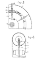
- the conveyor according to the invention comprises a flat upper driving pulley 1, a flat lower return pulley 2, an endless cable 3, disk- shaped entraining members 4 and a tubular enclosure 5.
- the driving motor is coupled to the shaft of the driving pulley 1 by which the disk- shaped entraining members 4 are entrained by cable 3 and convey upwards the bulk goods thereon indicated by 6 through the right-hand tube of the enclosure 5 to a discharge 7.
- the driving pulley 1 of the conveyor according to the invention is a flat pulley, fixed on a shaft 8 which can be driven by a motor, not shown, frequently through a reduction gear.
- the flat driving pulley 1 is provided with a continuous circumferential groove 9 as each normal cable pulley. This is also true for the return pulley 2.
- the pulleys 3 are continuous solid pulleys without recesses.
- a nestless pulley is provided with a continuous circumferential groove.
- FR-U-2,293,856 relates to a conveyor with pulleys provided with recesses or nests.
- the cable 3 is provided with elongated cylindrical sleeve members 10 clamped adjacent each other on the cable 3 or fixed thereon in another way.
- the entraining disks 4 are mounted axially nondisplaceable.
- each sleeve member 10 is in the form of a body of revolution in which the description line is a circle arc and the axis of the sleeve member 10 is the axis of the body of revolution.
- the radius of the circle arc is equal to the radius of the bottom of the groove 9 plus the largest web thickness of the sleeve member 10 thus in its center. In this way the cable 3 is kinked nowhere.
- pulleys 1 and 2 are continuous solid pulleys without recesses. With a pulley with nests the place of the entraining members is determined by the recesses in the pulleys.
- Each entraining member 4 is provided with a radial slot 11, see Fig. 4. When the entraining members 4 pass the pulley 1 or 2 the slots 11 run over the pulleys 1 and 2.
- pulleys 1 and 2 are not necessary to arrange the pulleys 1 and 2 in one and the same plane. They can cross each other or lie in another parallel plane. It is readily apparent that the shape of the enclosure 5 should be adapted thereto.
- said enclosure 5 needs not to be a closed tube.
- the conveying portion of the enclosure may be trough opened upwards. Even, the return portion of the enclosure may lack entirely.
- each entraining member 4 arrives in a correct rotational position at the pulleys 1 and 2. Therefore, it is necessary to guide the entraining members 4 in rotational direction over the entire traject. For example this can be accomplished by fixing a strip 12 against the inner side of the enclosure 5, see Fig. 1 and 5. Said strip 12 fits in the end of each slot 11 and is so designed that each slot 11 comes into the planes of the pulleys 1 and 2 also if said planes are not the same. At non-circular entraining members these strips 12 are superfluous.
- Fig. 1 and 2 the conveyor is implemented as self-filling apparatus. Thereby, at both sides of the shaft of the return pulley 2 screw conveyors 13 and 14 are mounted having opposite pitches. Thus, the bulk goods 15 to be picked up is conveyed by screws 13 and 14 to the apertures in the enclosure 5 after which the bulk goods are transported upwards by the entraining members 4.
- the screws 13 and 14 are driven from the pulley 1 through the cable 3 so that beneath no motor or the like needs to be arranged.
- Fig. 7 shows the conveyor according to fig. 5 and 6 as used for unloading a ship 18.
- a conveyor is hanging from a conveyor 19 of arbitrary type extending nearly horizontally and in its turn hangs from the mobile supporting construction 20. By descending the left-hand end of the conveyor 19 the digging depth into the ship 20 is varied. By journalling the conveyors 16 and 17 in opposite direction each corner of the ship 18 can be reached.
Claims (2)
Applications Claiming Priority (2)
| Application Number | Priority Date | Filing Date | Title |
|---|---|---|---|
| NL8007076 | 1980-12-29 | ||
| NL8007076 | 1980-12-29 |
Publications (2)
| Publication Number | Publication Date |
|---|---|
| EP0055879A1 EP0055879A1 (de) | 1982-07-14 |
| EP0055879B1 true EP0055879B1 (de) | 1986-08-27 |
Family
ID=19836376
Family Applications (1)
| Application Number | Title | Priority Date | Filing Date |
|---|---|---|---|
| EP19810201380 Expired EP0055879B1 (de) | 1980-12-29 | 1981-12-15 | Förderer bestehend aus Zugseil und Mitnehmer |
Country Status (2)
| Country | Link |
|---|---|
| EP (1) | EP0055879B1 (de) |
| DE (1) | DE3175241D1 (de) |
Families Citing this family (5)
| Publication number | Priority date | Publication date | Assignee | Title |
|---|---|---|---|---|
| NO151404C (no) * | 1982-12-01 | 1985-04-10 | Kaare Haahjem | Toemme- og trimmeanordning for styrtgods |
| FI76996C (fi) * | 1985-10-29 | 1989-01-10 | Kone Oy | Avlastningsanordning foer baot. |
| NL8702128A (nl) * | 1987-09-08 | 1989-04-03 | Figee Maschf | Inrichting voor het lossen van stortgoed. |
| IT1229022B (it) * | 1989-04-14 | 1991-07-12 | Camillo Pirovano | Fune con elementi radiali per trasporto di materiali a comportamento fluido in canalizzazioni. |
| JPH10265464A (ja) * | 1997-03-24 | 1998-10-06 | Sumitomo Pharmaceut Co Ltd | Ldl受容体遺伝子発現増強剤 |
Family Cites Families (7)
| Publication number | Priority date | Publication date | Assignee | Title |
|---|---|---|---|---|
| DE282119C (de) * | ||||
| US2765753A (en) * | 1953-11-05 | 1956-10-09 | John A Roebling S Sons Corp | Attachment for conveyor system line |
| US3139175A (en) * | 1962-11-20 | 1964-06-30 | Dearborn Fabricating & Enginee | Trolley bracket |
| FR2241479B1 (de) * | 1973-08-22 | 1979-05-11 | Orenstein & Koppel Ag | |
| FR2269467A1 (en) * | 1974-05-02 | 1975-11-28 | Pirovano Camillo | Pulverised material conveyor - uses eccentrically mounted flexible edged discs pulled by cable through a tube |
| AU504300B2 (en) * | 1974-12-03 | 1979-10-11 | Machinefabriek En Constructiewerkplaats Gebr. Klinkenberg Bv | Bulk material conveyor |
| IL49821A (en) * | 1976-06-17 | 1983-03-31 | Moledeth Dev Co Ltd | Elevator-conveyor for bulk material |
-
1981
- 1981-12-15 EP EP19810201380 patent/EP0055879B1/de not_active Expired
- 1981-12-15 DE DE8181201380T patent/DE3175241D1/de not_active Expired
Also Published As
| Publication number | Publication date |
|---|---|
| EP0055879A1 (de) | 1982-07-14 |
| DE3175241D1 (en) | 1986-10-02 |
Similar Documents
| Publication | Publication Date | Title |
|---|---|---|
| US3381801A (en) | Flexible conveyor | |
| GB2073691A (en) | Drive means for srting and/or conveying system | |
| EP0055879B1 (de) | Förderer bestehend aus Zugseil und Mitnehmer | |
| US3756382A (en) | Conveyor system | |
| KR100625932B1 (ko) | 공기 부상 벨트 컨베이어 장치 | |
| US4029200A (en) | Troughed rollers for bulk material handling | |
| US5765676A (en) | Package and bundle singulator | |
| KR850007186A (ko) | 반죽물의 유량조절장치 및 그 방법 | |
| US3311221A (en) | Tube conveyor | |
| GB2103194A (en) | Improvements in or relating to cup dispensing apparatus | |
| US3902588A (en) | Direction changing roller conveyor | |
| CN107934415A (zh) | 一种防堵塞多入口的螺旋输送机 | |
| GB2266287A (en) | Auger conveyor | |
| CN211664015U (zh) | 一种应用于截齿热处理生产线的网带 | |
| EP1586519B1 (de) | Einstellbare einheit zur übertragung ausgerichteter und aufrechter artikel von einem die artikel auf ihrer basis fördernden förderband auf ein hängeförderband | |
| CN211254492U (zh) | 一种组合秤的旋转加料机构 | |
| CN115158991B (zh) | 一种用于伺服电机联轴器的有序上料装置 | |
| US5228553A (en) | Drive mechanism for a conveyor of a printer circuit board processor | |
| US3895706A (en) | Arrangement for feeding the bulbs of electric vacuum devices | |
| EP0057167B1 (de) | Zuführvorrichtung für einen Förderer mit senkrechtem Förderrohr | |
| US4325479A (en) | Feed conveyor | |
| EP0059947A1 (de) | Förderband und Fördervorrichtung mit diesem Band | |
| US1226730A (en) | Belt conveyer. | |
| CN210794574U (zh) | 螺旋输送机 | |
| EP0726215A1 (de) | Fördervorrichtung für Schüttgüter, Antriebsrad und Kratzscheibe dafür |
Legal Events
| Date | Code | Title | Description |
|---|---|---|---|
| PUAI | Public reference made under article 153(3) epc to a published international application that has entered the european phase |
Free format text: ORIGINAL CODE: 0009012 |
|
| AK | Designated contracting states |
Designated state(s): BE DE FR GB IT NL |
|
| 17P | Request for examination filed |
Effective date: 19830103 |
|
| GRAA | (expected) grant |
Free format text: ORIGINAL CODE: 0009210 |
|
| AK | Designated contracting states |
Kind code of ref document: B1 Designated state(s): BE DE FR GB IT NL |
|
| ITF | It: translation for a ep patent filed |
Owner name: JACOBACCI & PERANI S.P.A. |
|
| REF | Corresponds to: |
Ref document number: 3175241 Country of ref document: DE Date of ref document: 19861002 |
|
| ET | Fr: translation filed | ||
| PLBE | No opposition filed within time limit |
Free format text: ORIGINAL CODE: 0009261 |
|
| STAA | Information on the status of an ep patent application or granted ep patent |
Free format text: STATUS: NO OPPOSITION FILED WITHIN TIME LIMIT |
|
| 26N | No opposition filed | ||
| PGFP | Annual fee paid to national office [announced via postgrant information from national office to epo] |
Ref country code: NL Payment date: 19871231 Year of fee payment: 7 |
|
| PGFP | Annual fee paid to national office [announced via postgrant information from national office to epo] |
Ref country code: FR Payment date: 19881213 Year of fee payment: 8 |
|
| ITTA | It: last paid annual fee | ||
| PGFP | Annual fee paid to national office [announced via postgrant information from national office to epo] |
Ref country code: DE Payment date: 19890131 Year of fee payment: 8 |
|
| PG25 | Lapsed in a contracting state [announced via postgrant information from national office to epo] |
Ref country code: GB Effective date: 19891215 |
|
| PG25 | Lapsed in a contracting state [announced via postgrant information from national office to epo] |
Ref country code: BE Effective date: 19891231 |
|
| BERE | Be: lapsed |
Owner name: SPAANS CORNELIS Effective date: 19891231 |
|
| PG25 | Lapsed in a contracting state [announced via postgrant information from national office to epo] |
Ref country code: NL Effective date: 19900701 |
|
| GBPC | Gb: european patent ceased through non-payment of renewal fee | ||
| NLV4 | Nl: lapsed or anulled due to non-payment of the annual fee | ||
| PG25 | Lapsed in a contracting state [announced via postgrant information from national office to epo] |
Ref country code: FR Effective date: 19900831 |
|
| PG25 | Lapsed in a contracting state [announced via postgrant information from national office to epo] |
Ref country code: DE Effective date: 19900901 |
|
| REG | Reference to a national code |
Ref country code: FR Ref legal event code: ST |