EP0055656B1 - Verfahren zur dichten Befestigung zweier Schalen - Google Patents
Verfahren zur dichten Befestigung zweier Schalen Download PDFInfo
- Publication number
- EP0055656B1 EP0055656B1 EP81402018A EP81402018A EP0055656B1 EP 0055656 B1 EP0055656 B1 EP 0055656B1 EP 81402018 A EP81402018 A EP 81402018A EP 81402018 A EP81402018 A EP 81402018A EP 0055656 B1 EP0055656 B1 EP 0055656B1
- Authority
- EP
- European Patent Office
- Prior art keywords
- shell
- bead
- groove
- radial
- annular wall
- Prior art date
- Legal status (The legal status is an assumption and is not a legal conclusion. Google has not performed a legal analysis and makes no representation as to the accuracy of the status listed.)
- Expired
Links
Images

Classifications
-
- B—PERFORMING OPERATIONS; TRANSPORTING
- B23—MACHINE TOOLS; METAL-WORKING NOT OTHERWISE PROVIDED FOR
- B23P—METAL-WORKING NOT OTHERWISE PROVIDED FOR; COMBINED OPERATIONS; UNIVERSAL MACHINE TOOLS
- B23P11/00—Connecting or disconnecting metal parts or objects by metal-working techniques not otherwise provided for
-
- Y—GENERAL TAGGING OF NEW TECHNOLOGICAL DEVELOPMENTS; GENERAL TAGGING OF CROSS-SECTIONAL TECHNOLOGIES SPANNING OVER SEVERAL SECTIONS OF THE IPC; TECHNICAL SUBJECTS COVERED BY FORMER USPC CROSS-REFERENCE ART COLLECTIONS [XRACs] AND DIGESTS
- Y10—TECHNICAL SUBJECTS COVERED BY FORMER USPC
- Y10T—TECHNICAL SUBJECTS COVERED BY FORMER US CLASSIFICATION
- Y10T29/00—Metal working
- Y10T29/49—Method of mechanical manufacture
- Y10T29/49826—Assembling or joining
- Y10T29/49877—Assembling or joining of flexible wall, expansible chamber devices [e.g., bellows]
-
- Y—GENERAL TAGGING OF NEW TECHNOLOGICAL DEVELOPMENTS; GENERAL TAGGING OF CROSS-SECTIONAL TECHNOLOGIES SPANNING OVER SEVERAL SECTIONS OF THE IPC; TECHNICAL SUBJECTS COVERED BY FORMER USPC CROSS-REFERENCE ART COLLECTIONS [XRACs] AND DIGESTS
- Y10—TECHNICAL SUBJECTS COVERED BY FORMER USPC
- Y10T—TECHNICAL SUBJECTS COVERED BY FORMER US CLASSIFICATION
- Y10T29/00—Metal working
- Y10T29/49—Method of mechanical manufacture
- Y10T29/49826—Assembling or joining
- Y10T29/49908—Joining by deforming
- Y10T29/49909—Securing cup or tube between axially extending concentric annuli
- Y10T29/49913—Securing cup or tube between axially extending concentric annuli by constricting outer annulus
-
- Y—GENERAL TAGGING OF NEW TECHNOLOGICAL DEVELOPMENTS; GENERAL TAGGING OF CROSS-SECTIONAL TECHNOLOGIES SPANNING OVER SEVERAL SECTIONS OF THE IPC; TECHNICAL SUBJECTS COVERED BY FORMER USPC CROSS-REFERENCE ART COLLECTIONS [XRACs] AND DIGESTS
- Y10—TECHNICAL SUBJECTS COVERED BY FORMER USPC
- Y10T—TECHNICAL SUBJECTS COVERED BY FORMER US CLASSIFICATION
- Y10T29/00—Metal working
- Y10T29/49—Method of mechanical manufacture
- Y10T29/49826—Assembling or joining
- Y10T29/49908—Joining by deforming
- Y10T29/49915—Overedge assembling of seated part
- Y10T29/49917—Overedge assembling of seated part by necking in cup or tube wall
Definitions
- This invention relates to a method of fastening a first shell to a second shell to form a sealed housing, for instance for a vacuum or pneumatic servomotor for power brake systems.
- an object of the present invention to provide an improved method of fastening shells together which avoids the above-mentioned drawback and makes it sure to correctly seal the interior of the housing from the surrounding environment under all circumstances.
- An essential advantage of this invention results from the deformation that is put into the annular wall after the crimping operation to urge the bead on the diaphragm assembly into sealing engagement with the first and second shells. Any leak which is detected after the initial deformation of the annular wall can easily be corrected by increasing the deformation to adequately flow the bead into the groove to achieve the desired sealing.
- Another advantage of this invention occurs since the frictional resistance between the bead, rib and groove is sufficient to prevent relative movement between the first and second shells, thereby eliminating the need for slots and tabs as in the prior art.
- the servomotor shown in the drawings is assembled in a known per se manner with the exception of the fastening of the first shell 10 to a second shell 12.
- the second shell 12 is placed on a fixture 16.
- the second shell 12 has a radial wall 18 with a conical section 20 projecting therefrom.
- a flange 24 is rolled back from the conical section to produce a groove 26.
- the peripheral edge 28 of the flange section 24 is at a substantially fixed radius from the axis of the second shell 12.
- a first bead 30 of diaphragm 32 snaps into groove 26 and a second bead 34 is positioned in a groove 36 on hub 38 to hold a backing plate 44 on hub 38.
- Hub 38 which retains the valve, not shown, for controlling the operation of the resulting servomotor, has a projection 40 that extends through an opening in shell 12. The hub 38, diaphragm 32, and shell 12 cooperate to define a chamber 46.
- a crimping apparatus 56 of the type disclosed in US Patent No. 3 158 930 is brought into engagement with wall 58.
- tangs 60, 60' ... 60 n are punched in wall 58.
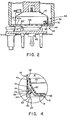
- the tangs 60, 60' ... 60 n engage flange 24 to hold the flange 24 against shoulder 54, as shown in Figure 2, and thereby connect the first shell 10 with the second shell 12 to form housing 62.
- Fixture 64 may be independent from a known production line or the final assembly station thereof.
- groove 76 develops in the side wall 72 as shown in Figure 4.
- the formation of groove 76 creates an annular rib 74 on the interior 52 of wall 72 that compresses bead 30 causing the bead 30 to flow toward and into groove 26 to seal chambers 46 and 47 from each other and from the surrounding environment in a manner as best shown in Figure 4.
- the compressionary force of the rib 74 on the bead 30 can be changed by changing the size and depth of groove 76.
- an unacceptable servomotor could be placed in fixture 64 and groove 76 increased to create a larger rib 74 and thereby compensate for such nonmatching of parts even though they individually meet their particular manufacturing standards.
Landscapes
- Engineering & Computer Science (AREA)
- Mechanical Engineering (AREA)
- Diaphragms And Bellows (AREA)
- Braking Systems And Boosters (AREA)
- Sealing Devices (AREA)
Claims (2)
Applications Claiming Priority (2)
| Application Number | Priority Date | Filing Date | Title |
|---|---|---|---|
| US219078 | 1980-12-22 | ||
| US06/219,078 US4366612A (en) | 1980-12-22 | 1980-12-22 | Method of fastening a first shell to a second shell with a diaphragm bead therebetween |
Publications (3)
| Publication Number | Publication Date |
|---|---|
| EP0055656A2 EP0055656A2 (de) | 1982-07-07 |
| EP0055656A3 EP0055656A3 (en) | 1982-08-11 |
| EP0055656B1 true EP0055656B1 (de) | 1985-07-31 |
Family
ID=22817772
Family Applications (1)
| Application Number | Title | Priority Date | Filing Date |
|---|---|---|---|
| EP81402018A Expired EP0055656B1 (de) | 1980-12-22 | 1981-12-17 | Verfahren zur dichten Befestigung zweier Schalen |
Country Status (7)
| Country | Link |
|---|---|
| US (1) | US4366612A (de) |
| EP (1) | EP0055656B1 (de) |
| JP (1) | JPS57134070A (de) |
| AR (1) | AR229945A1 (de) |
| BR (1) | BR8108464A (de) |
| CA (1) | CA1174527A (de) |
| DE (1) | DE3171625D1 (de) |
Cited By (1)
| Publication number | Priority date | Publication date | Assignee | Title |
|---|---|---|---|---|
| DE102010034827A1 (de) | 2010-08-19 | 2012-02-23 | Lucas Automotive Gmbh | Unterdruckbremskraftverstärker mit einer montagefreundlichen Kammeranordnung und Verfahren zur Montage eines Unterdruckbremskraftverstärkers |
Families Citing this family (10)
| Publication number | Priority date | Publication date | Assignee | Title |
|---|---|---|---|---|
| DE3246152C2 (de) * | 1982-12-14 | 1985-01-03 | Fa. Carl Freudenberg, 6940 Weinheim | Verfahren zur Herstellung eines Wellendichtringes |
| CA1247591A (en) * | 1984-06-28 | 1988-12-28 | Kevin E. Stay | Tank header plate connection |
| DE3629123C3 (de) * | 1986-08-27 | 1994-04-28 | Grundfos International A S Bje | Mehrstufige Inline-Kreiselpumpe |
| DE3866987D1 (de) * | 1987-07-21 | 1992-01-30 | Bendix Europ Services Tech | Zusammenbauverfahren fuer einen servomotor und nach diesem verfahren zusammengebauter servomotor. |
| DE4332611C1 (de) * | 1993-09-24 | 1995-01-05 | Lucas Ind Plc | Kraftverstärkergehäuse, insbesondere für Fahrzeugbremsanlagen, und Verfahren zum Zusammenbauen eines solchen Kraftverstärkergehäuses |
| US6390567B1 (en) * | 2001-08-20 | 2002-05-21 | Robert Bosch Corporation | Housing for a brake booster |
| JP4671262B2 (ja) * | 2003-01-21 | 2011-04-13 | 日本碍子株式会社 | 半導体加熱装置 |
| FR2860472B1 (fr) * | 2003-10-06 | 2006-01-20 | Bosch Gmbh Robert | Servomoteur pneumatique d'assistance au freinage comportant un diaphragme serti |
| US7048342B1 (en) | 2004-01-27 | 2006-05-23 | Robert Bosch Corporation | Housing for a brake booster |
| US7743894B2 (en) * | 2006-09-19 | 2010-06-29 | Bendix Spicer Foundation Brake Llc | Brake actuator reinforcement and method of attaching same |
Family Cites Families (11)
| Publication number | Priority date | Publication date | Assignee | Title |
|---|---|---|---|---|
| US2891362A (en) * | 1952-08-11 | 1959-06-23 | Hunt Capacitors Ltd A | Method of encasing electrical capacitors |
| US3158930A (en) * | 1961-05-01 | 1964-12-01 | Bendix Corp | Method of manufacturing assembly fluid pressure motors |
| GB1140611A (en) * | 1966-05-19 | 1969-01-22 | Girling Ltd | Improvements in and relating to tubular housing structures |
| US3914852A (en) * | 1971-08-14 | 1975-10-28 | Gkn Transmissions Ltd | Method of securing a sealing boot or like sealing member to an outer member of a universal joint |
| JPS5320627B2 (de) * | 1973-12-29 | 1978-06-28 | ||
| US3977299A (en) * | 1974-11-25 | 1976-08-31 | The Bendix Corporation | Fastening means for closing a servomotor |
| JPS5746678Y2 (de) * | 1978-08-01 | 1982-10-14 | ||
| US4296680A (en) * | 1978-12-01 | 1981-10-27 | Jidosha Kiki Co., Ltd. | Coupled shells for vacuum power servo booster |
| GB2038447B (en) * | 1978-12-21 | 1982-11-10 | Automotive Prod Co Ltd | Rolling diaphragm apparatus |
| US4268945A (en) * | 1979-06-05 | 1981-05-26 | The Bendix Corporation | Method of assemblying a sealed structure |
| US4295492A (en) * | 1979-11-13 | 1981-10-20 | Greer Hydraulics, Incorporated | Low cost accumulator device |
-
1980
- 1980-12-22 US US06/219,078 patent/US4366612A/en not_active Expired - Fee Related
-
1981
- 1981-12-15 AR AR287818A patent/AR229945A1/es active
- 1981-12-17 DE DE8181402018T patent/DE3171625D1/de not_active Expired
- 1981-12-17 EP EP81402018A patent/EP0055656B1/de not_active Expired
- 1981-12-22 BR BR8108464A patent/BR8108464A/pt not_active IP Right Cessation
- 1981-12-22 CA CA000392958A patent/CA1174527A/en not_active Expired
- 1981-12-22 JP JP56206290A patent/JPS57134070A/ja active Pending
Cited By (2)
| Publication number | Priority date | Publication date | Assignee | Title |
|---|---|---|---|---|
| DE102010034827A1 (de) | 2010-08-19 | 2012-02-23 | Lucas Automotive Gmbh | Unterdruckbremskraftverstärker mit einer montagefreundlichen Kammeranordnung und Verfahren zur Montage eines Unterdruckbremskraftverstärkers |
| WO2012022424A1 (de) | 2010-08-19 | 2012-02-23 | Lucas Automotive Gmbh | Unterdruckbremskraftverstärker mit einer montagefreundlichen kammeranordnung und verfahren zur montage eines unterdruckbremskraftverstärkers |
Also Published As
| Publication number | Publication date |
|---|---|
| CA1174527A (en) | 1984-09-18 |
| EP0055656A2 (de) | 1982-07-07 |
| JPS57134070A (en) | 1982-08-19 |
| EP0055656A3 (en) | 1982-08-11 |
| US4366612A (en) | 1983-01-04 |
| DE3171625D1 (en) | 1985-09-05 |
| AR229945A1 (es) | 1984-01-31 |
| BR8108464A (pt) | 1982-10-19 |
Similar Documents
| Publication | Publication Date | Title |
|---|---|---|
| EP0055656A2 (de) | Verfahren zur dichten Befestigung zweier Schalen | |
| US4131285A (en) | Bonded TFE lip seal | |
| US6328351B1 (en) | Pipe joint with enlarged metal pipe and method for manufacturing same | |
| US3857156A (en) | Method of making tetrafluoroethylene sealing elements with hydrodynamic action | |
| US4026563A (en) | Oil seal with locking bead and O. D. sealing rib | |
| EP1255940B1 (de) | Wellendichtung mit eimem hydrodynamisch oberflächenstrukturiertem laufring | |
| US5341566A (en) | Conduit attachment | |
| US4747605A (en) | Fluid pressure seal with pressure distortion barrier | |
| KR100312036B1 (ko) | 플레이트의홀형성방법및홀형성용펀치 | |
| EP3412374B1 (de) | Verfahren zur herstellung eines federelements für eine dichtungsvorrichtung | |
| WO1995011072A1 (en) | Oil and fuel filter canister and housing | |
| US5163720A (en) | Pipe joint | |
| US20030201610A1 (en) | Oil transfer seal assembly | |
| EP0668451A1 (de) | Dichtungsvorrichtung für Lager und Verfahren zur Herstellung | |
| US4738186A (en) | Diaphragm for a servomotor | |
| EP0660907A1 (de) | Abgabevorrichtung für karbonisierte getränke | |
| US4278218A (en) | Seal | |
| SU1625650A1 (ru) | Способ герметичной заделки отверстий в концевых трубчатых элементах | |
| EP1141577B1 (de) | Kolben und verfahren zu seiner herstellung | |
| US5052697A (en) | Sealing member for ferrofluid seal and method of producing the same | |
| US20050087930A1 (en) | Locating bore for press fit and sealing of a press fit component | |
| US6230900B1 (en) | Filter assembly and process for producing the same | |
| JPH04125359A (ja) | 筒体の密閉構造及びその加工方法 | |
| JPH08247357A (ja) | フランジ継手及びその成形方法 | |
| EP1022497B1 (de) | Vorrichtung zur Formung einer Verschlusskappe und Verfahren zur Herstellung einer Verschlusskappe |
Legal Events
| Date | Code | Title | Description |
|---|---|---|---|
| PUAI | Public reference made under article 153(3) epc to a published international application that has entered the european phase |
Free format text: ORIGINAL CODE: 0009012 |
|
| PUAL | Search report despatched |
Free format text: ORIGINAL CODE: 0009013 |
|
| 17P | Request for examination filed |
Effective date: 19811223 |
|
| AK | Designated contracting states |
Designated state(s): DE FR GB |
|
| AK | Designated contracting states |
Designated state(s): DE FR GB |
|
| GRAA | (expected) grant |
Free format text: ORIGINAL CODE: 0009210 |
|
| AK | Designated contracting states |
Designated state(s): DE FR GB |
|
| REF | Corresponds to: |
Ref document number: 3171625 Country of ref document: DE Date of ref document: 19850905 |
|
| ET | Fr: translation filed | ||
| PLBE | No opposition filed within time limit |
Free format text: ORIGINAL CODE: 0009261 |
|
| STAA | Information on the status of an ep patent application or granted ep patent |
Free format text: STATUS: NO OPPOSITION FILED WITHIN TIME LIMIT |
|
| 26N | No opposition filed | ||
| GBPC | Gb: european patent ceased through non-payment of renewal fee | ||
| PG25 | Lapsed in a contracting state [announced via postgrant information from national office to epo] |
Ref country code: FR Free format text: LAPSE BECAUSE OF NON-PAYMENT OF DUE FEES Effective date: 19870831 |
|
| PG25 | Lapsed in a contracting state [announced via postgrant information from national office to epo] |
Ref country code: DE Effective date: 19870901 |
|
| REG | Reference to a national code |
Ref country code: FR Ref legal event code: ST |
|
| PG25 | Lapsed in a contracting state [announced via postgrant information from national office to epo] |
Ref country code: GB Free format text: LAPSE BECAUSE OF NON-PAYMENT OF DUE FEES Effective date: 19881121 |