EP0055314A1 - Gestion d'énergie - Google Patents
Gestion d'énergie Download PDFInfo
- Publication number
- EP0055314A1 EP0055314A1 EP80304769A EP80304769A EP0055314A1 EP 0055314 A1 EP0055314 A1 EP 0055314A1 EP 80304769 A EP80304769 A EP 80304769A EP 80304769 A EP80304769 A EP 80304769A EP 0055314 A1 EP0055314 A1 EP 0055314A1
- Authority
- EP
- European Patent Office
- Prior art keywords
- demand
- loads
- residential
- utility
- limit
- Prior art date
- Legal status (The legal status is an assumption and is not a legal conclusion. Google has not performed a legal analysis and makes no representation as to the accuracy of the status listed.)
- Withdrawn
Links
Images


Classifications
-
- H—ELECTRICITY
- H02—GENERATION; CONVERSION OR DISTRIBUTION OF ELECTRIC POWER
- H02J—CIRCUIT ARRANGEMENTS OR SYSTEMS FOR SUPPLYING OR DISTRIBUTING ELECTRIC POWER; SYSTEMS FOR STORING ELECTRIC ENERGY
- H02J3/00—Circuit arrangements for ac mains or ac distribution networks
- H02J3/18—Arrangements for adjusting, eliminating or compensating reactive power in networks
- H02J3/1821—Arrangements for adjusting, eliminating or compensating reactive power in networks using shunt compensators
- H02J3/1871—Methods for planning installation of shunt reactive power compensators
-
- H—ELECTRICITY
- H02—GENERATION; CONVERSION OR DISTRIBUTION OF ELECTRIC POWER
- H02J—CIRCUIT ARRANGEMENTS OR SYSTEMS FOR SUPPLYING OR DISTRIBUTING ELECTRIC POWER; SYSTEMS FOR STORING ELECTRIC ENERGY
- H02J3/00—Circuit arrangements for ac mains or ac distribution networks
- H02J3/12—Circuit arrangements for ac mains or ac distribution networks for adjusting voltage in ac networks by changing a characteristic of the network load
- H02J3/14—Circuit arrangements for ac mains or ac distribution networks for adjusting voltage in ac networks by changing a characteristic of the network load by switching loads on to, or off from, network, e.g. progressively balanced loading
- H02J3/144—Demand-response operation of the power transmission or distribution network
-
- H—ELECTRICITY
- H02—GENERATION; CONVERSION OR DISTRIBUTION OF ELECTRIC POWER
- H02J—CIRCUIT ARRANGEMENTS OR SYSTEMS FOR SUPPLYING OR DISTRIBUTING ELECTRIC POWER; SYSTEMS FOR STORING ELECTRIC ENERGY
- H02J3/00—Circuit arrangements for ac mains or ac distribution networks
- H02J3/18—Arrangements for adjusting, eliminating or compensating reactive power in networks
-
- H—ELECTRICITY
- H02—GENERATION; CONVERSION OR DISTRIBUTION OF ELECTRIC POWER
- H02J—CIRCUIT ARRANGEMENTS OR SYSTEMS FOR SUPPLYING OR DISTRIBUTING ELECTRIC POWER; SYSTEMS FOR STORING ELECTRIC ENERGY
- H02J2310/00—The network for supplying or distributing electric power characterised by its spatial reach or by the load
- H02J2310/10—The network having a local or delimited stationary reach
-
- H—ELECTRICITY
- H02—GENERATION; CONVERSION OR DISTRIBUTION OF ELECTRIC POWER
- H02J—CIRCUIT ARRANGEMENTS OR SYSTEMS FOR SUPPLYING OR DISTRIBUTING ELECTRIC POWER; SYSTEMS FOR STORING ELECTRIC ENERGY
- H02J2310/00—The network for supplying or distributing electric power characterised by its spatial reach or by the load
- H02J2310/50—The network for supplying or distributing electric power characterised by its spatial reach or by the load for selectively controlling the operation of the loads
- H02J2310/56—The network for supplying or distributing electric power characterised by its spatial reach or by the load for selectively controlling the operation of the loads characterised by the condition upon which the selective controlling is based
- H02J2310/58—The condition being electrical
- H02J2310/60—Limiting power consumption in the network or in one section of the network, e.g. load shedding or peak shaving
-
- Y—GENERAL TAGGING OF NEW TECHNOLOGICAL DEVELOPMENTS; GENERAL TAGGING OF CROSS-SECTIONAL TECHNOLOGIES SPANNING OVER SEVERAL SECTIONS OF THE IPC; TECHNICAL SUBJECTS COVERED BY FORMER USPC CROSS-REFERENCE ART COLLECTIONS [XRACs] AND DIGESTS
- Y02—TECHNOLOGIES OR APPLICATIONS FOR MITIGATION OR ADAPTATION AGAINST CLIMATE CHANGE
- Y02B—CLIMATE CHANGE MITIGATION TECHNOLOGIES RELATED TO BUILDINGS, e.g. HOUSING, HOUSE APPLIANCES OR RELATED END-USER APPLICATIONS
- Y02B70/00—Technologies for an efficient end-user side electric power management and consumption
- Y02B70/30—Systems integrating technologies related to power network operation and communication or information technologies for improving the carbon footprint of the management of residential or tertiary loads, i.e. smart grids as climate change mitigation technology in the buildings sector, including also the last stages of power distribution and the control, monitoring or operating management systems at local level
- Y02B70/3225—Demand response systems, e.g. load shedding, peak shaving
-
- Y—GENERAL TAGGING OF NEW TECHNOLOGICAL DEVELOPMENTS; GENERAL TAGGING OF CROSS-SECTIONAL TECHNOLOGIES SPANNING OVER SEVERAL SECTIONS OF THE IPC; TECHNICAL SUBJECTS COVERED BY FORMER USPC CROSS-REFERENCE ART COLLECTIONS [XRACs] AND DIGESTS
- Y02—TECHNOLOGIES OR APPLICATIONS FOR MITIGATION OR ADAPTATION AGAINST CLIMATE CHANGE
- Y02E—REDUCTION OF GREENHOUSE GAS [GHG] EMISSIONS, RELATED TO ENERGY GENERATION, TRANSMISSION OR DISTRIBUTION
- Y02E40/00—Technologies for an efficient electrical power generation, transmission or distribution
- Y02E40/30—Reactive power compensation
-
- Y—GENERAL TAGGING OF NEW TECHNOLOGICAL DEVELOPMENTS; GENERAL TAGGING OF CROSS-SECTIONAL TECHNOLOGIES SPANNING OVER SEVERAL SECTIONS OF THE IPC; TECHNICAL SUBJECTS COVERED BY FORMER USPC CROSS-REFERENCE ART COLLECTIONS [XRACs] AND DIGESTS
- Y04—INFORMATION OR COMMUNICATION TECHNOLOGIES HAVING AN IMPACT ON OTHER TECHNOLOGY AREAS
- Y04S—SYSTEMS INTEGRATING TECHNOLOGIES RELATED TO POWER NETWORK OPERATION, COMMUNICATION OR INFORMATION TECHNOLOGIES FOR IMPROVING THE ELECTRICAL POWER GENERATION, TRANSMISSION, DISTRIBUTION, MANAGEMENT OR USAGE, i.e. SMART GRIDS
- Y04S20/00—Management or operation of end-user stationary applications or the last stages of power distribution; Controlling, monitoring or operating thereof
- Y04S20/20—End-user application control systems
- Y04S20/222—Demand response systems, e.g. load shedding, peak shaving
Definitions
- This invention relates to a method for electrical energy management for controlling power consumption in each of a plurality of residential circuits, each circuit having a plurality of loads.
- the utility itself may find that the reduction in total electrical energy consumption reduces the utility's revenue to the point that it must, in turn, raise the utility charge per unit of electrical power consumed to the point that the user's electrical utility bills may even exceed the bills he customarily received before his power usage was curtailed.
- each residential customer is allowed to choose his own demand limit and is encouraged to set his own limit to the lowest possible value by imposing considerably higher rates for power used during the utility's peak demand periods.
- each consumer can decide for himself the extent to which peak usage curtailment programs will be allowed to interfere with his lifestyle.
- Such utility control is required in the event of an emergency requiring a shutdown of part of the generating facilities and is desirable to enable the utility to program the construction of additional generating facilities as the demand on its existing facilities rises due to population shifts and increased usage by existing customers.
- a utility command to shed all water heaters or air conditioners may, nevertheless, fail to achieve the desired reduction in the utility's total load or the reduction thus achieved may be greater than anticipated and desired, causing the utility company to lose revenues and ultimately increasing the unit cost of the power to the residential consumer.
- a command to shed all water heaters (a resistive load) or all air conditioners (an inductive load) may cause serious imbalance between the resistive and reactive components of the utility's total load, materially and undesirably affecting the power factor of the load.
- an energy management method for controlling electrical power consumption in each of a plurality of residential circuits having a plurality of loads including non-thermal loads having unpredictable demands, each said circuit having a controller for shedding and restoring certain ones of the loads in said residential circuit and including means for receiving utility-generated shed-restore signals from a remote location, and controlling the use by the residential consumer of certain of the loads in his residence by utility-generated shed-restore signals, the improvement in said method comprising the steps of:
- a preferred method of electrical energy management according to the invention enables the utility to modify the demand limits initially selected by individual residential customers, impacts fairly and equally on all of the utility's customers' lifestyles and enables the utility to exercise such control without adversely affecting its power factor.
- the apparatus of Figs. 1 to 3 provides improvements in the prior art methods for managing electrical energy consumption in a plurality of residential circuits having a plurality of loads.
- a controller is provided for each circuit for shedding and restoring certain ones of the loads in the circuit.
- the controller includes means for receiving utility-generated shed-restore signals from a remote location and control of the total demand imposed on the utility power distribution system is attempted by utilizing utility-generated signals to shed or restore specific ones of the loads in the circuit.
- the apparatus of Figs. 1 to 3 provides a method of electrical energy management in which each residential circuit is provided with a variable-limit demand controller, including means for receiving utility-generated demand-limit signals from a remote location.
- a demand limit is established for each of the residential circuits which is independent of which specific loads in the circuit are responsible for the demand and signals are generated from the remote loaction to vary the demand limit proportionately in all of the residential circuits.
- the method of the present invention further comprises the steps of providing each residential circuit with separate variable limit demand controllers for the resistive loads and the reactive loads in the residential circuit, separate demand limits are established for the resistive and the reactive loads in the circuit and separate signals are generated by the utility from the remote location to separately vary the resistive and reactive demand limits proportionately in all of the residential circuits.
- the resistive and reactive demand limits are adjustably varied to achieve an improved power factor of the load on the utility power generating facilities.
- the methods of the present invention are equally applicable whether the customer initially selects the demand limits or whether the utility arbitrarily imposes such initial demand limit.
- Fig. 1 depicts a typical power generation-distribution system which serves a plurality of individual residential consumers in which the power 10 generated in the utility's power generation facilities 11 is transmitted through a plurality of substations 12 to individual residences, each provided with a residential load controller ("RLC") 13.
- RLC residential load controller
- the power consumed by the residence 13 served by each substation 12 is monitored by metering facilities 15 and the metering information 16 is provided to a power dispatch facility 17 equipped with a radio transmitter 18. Additional information 19 is supplied to the power dispatch facility 17 from the power generation facilities 11 relating to the status of the various elements of the power generation facilities, the total available power, etc.
- the information 19 from the power generation facilities and the metering information 16 are utilized to make decisions in the power dispatch facility 17 as to whether the total load 10 on the power generation facilities 11 must be decreased or can be increased and the amount of such decrease or increase. These decisions, in the form of demand limit increase or decrease signals 21 are sent to the transmitter 18 which transmits the commands from the radio transmitting antenna 2.2 to the receiving antennas 23 located at each of the residential load controllers 13.
- commands are sent from the transmitter antenna 22 to the receiving antennas 23 of each of the residential load controllers 13 to reduce the demand limit in each individual residence by an equal percentage, which total reduction equals the desired reduction of the total load 10 if each residence is using power at or just under its respective demand limit. If, however, some of the individual residences are not using power at their respective demand limits, the reduction in the total load 10 on the generating facilities 11 may not be completely effected and power dispatch facility 17 may issue a second and possible subsequent commands for a further percentage reduction in the demand limits in each of the residences.
- the utility Upon completion of these measures, the utility will have achieved the desired reduction in the total load 10 on its generation facilities 11. Similarly, the utility may determine through its power dispatch facilities that the total load 10 on the power generation facilities 11 may be desirably increased and signals are transmitted to the individual load controllers 13 to effect an equal percentage increase in the demand limits of each of the controllers 13.
- the utility company's objective has been fulfilled with a minimum and equal impact upon the lifestyle of the power consumers in each of the residences, i.e., the demand limit (previously selected by each consumer or imposed by the utility on each consumer) has been adjusted downwardly (or upwardly where possible) without arbitrarily imposing on the consumer the choice as to which specific appliances or loads in his residence must be turned off in order to avoid exceeding the new demand limit.
- customer 1 of sub-station "a” who may be drying laundry can continue doing so provided he is willing to forego a simultaneous hot shower and customer 2 of sub-station "n", who is away from home, can nevertheless keep his residence cool and his pool clean by the automatic operation of his air conditioner and pool filtration-pump because he does not need to use cooking, laundry or bathing facilities while away from home.
- each residential consumer has been subjected to precisely the same utility-control, namely, the demand limit for each residence has been reduced by an equal percentage.
- the individual residential demand limits can be restored simultaneously and by a similarly equal percentage.
- any one of various suitable means can be employed to transmit the signals from the transmitter 18 to the RLC's 13.
- the signals could be transmitted for the transmitter 18 to the RLC 13 by telephone lines or by high frequency signals imposed on the power company's own distribution lines.
- each sub-station in the power distribution network of Fig. 1 could make its own power dispatch decisions and transmit the demand limit commands directly to its own residential consumers.
- FIG. 2 schematically depicts the elements which are utilized in accordance with the invention at each individual residence.
- a residence 31 is depicted which has a plurality of loads consisting of uncontrolled loads 32 and controlled loads 33 comprising a residential circuit.
- Electrical power 34 is transmitted from the utility power buss through a sensor 35 which may, for example, measure either instantaneous power or current demand. The power is transmitted directly from the sensor 35 to the uncontrolled loads 32 via the line 33a.
- power to the controlled loads is transmitted through a residential load controller (RLC) 36 which contains a plurality of on-off load controlled devices (LCD) 37.
- RLC residential load controller
- Utility generated signals 38 from a radio antenna, telephone line, or from the utility's own power line are fed to a receiver 39.
- a control panel 41 is provided which allows each residence consumer to select and impose an upper limit on the demand which can be imposed by all of the loads (controlled and uncontrolled) in the residence 31.
- the customer-selected demand limit information 42, the received utility-generated signals 43 and the total demand information data 44 are fed to the logic 45 of a computer such as a microprocessor which correlates the information and transmits shed-restore commands 46 to the load controlled devices 37.
- the operation of the system of Fig. 2 in accordance with the method of the invention may be illustrated by assuming that the residential consumer has imposed a demand limit of 10kw on his residence and, with all loads in operation, the actual demand imposed by the loads is 9.8 kw.
- the utility In order to effectuate a reduction in its overall load, the utility generates signals commanding a 10% reduction in demand limits for all residences in its distribution network. These signals 38 are detected to the receiver 39 and fed to the logic of the microprocessor which overrides the customer-selected 10 kw demand limit and reduces.the limit to 9.0 kw.
- the logic 45 of the microprocessor will generate sequentially shed signals 46 to a sufficient number of the LCD's 37 to shed enough loads to reduce the actual demand of the residence 31 to 9.0 kw or lower.
- appropriate command signals can be sent to the load controller 36 to countermand any previous limit- decrease commands, restoring the demand limit to the value selected by the residential consumer by manipulation of the controllers 41. If the initial demand limit had been imposed by the utility through the signals 38 received and transmitted to the logic 45, this demand limit or an even higher demand limit may be imposed through additional signals 38 received and transmitted to the logic 45. In either case, upon sensing the higher demand limit, the logic 45 issues restore signals to the load control devices 37 to restore loads previously shed until the metering data 44 reflects that the total load on the residence 31 is either equal to or just below the demand limit.
- the restoration of the loads may be accomplished in the reverse sequence in which they were shed (the customer establishing such load priority) or in accordance with various other restoration sequences.
- the loads are restored in reverse sequence of shedding, if possible, but if such sequential restoration is impossible, the loads may be restored out of sequence until the total load is as close as possible to the demand limit, without exceeding the limit.
- This load restoration optimization method which is utilized in accordance with the presently preferred embodiment of the present invention is disclosed in the co-pending application of Hedges et al, Serial No. 909,850, filed May 26, 1978, entitled "ELECTRICAL LOAD RESTORATION METHOD”.
- the utility-generated signals may be transmitted to the load controller 36 of Fig. 2 by any suitable technique.
- the receiver 39 is and FM multiplex receiver and the logic 45 is contained in a semi-custom microprocessor Model MC6801 manufactured by Motorola.
- the LCD's 37 are triac but, as will be apparent to those skilled in the art, other devices such as conventional relays could be employed.
- the meter 35 of Fig. 2 is a conventional residential electrical utility meter modified in accordance with the disclosure of the co-pending application Serial No. 923,010 of Paul J.
- Emerson filed July 10, 1978, entitled "OPTICAL SYSTEM FOR TRANSMITTING ELECTRICAL ENERGY CONSUMPTION SIGNALS FROM A UTILITY METER", which utilizes a fiber-optics bundle extending inside the enclosure to sense light signals generated inside the enclosure in response to the rotation of the disk to transmit the light signals to a photosensitive device outside the meter enclosure, which signals are converted by a counter and appropriate logic to instantaneous power demand-limit information.
- any other suitable meter could be employed which provides either instantaneous power demand or instantaneous current demand information.
- the methods of the invention, described above, can also be utilized, in accordance with a further preferred embodiment of the invention, to improve the power factor of the utility company's total load or the power factor of the load on any one of the one or more sub-divisions of the utility company's power distribution network such as, for example, the power factor of a load on any one particular utility substation.
- the power factor of a load is dependent upon the relationship of the resistive and the reactive components of the load.
- the typical residential load ' consists of resistive loads such as water heaters, cooking stoves, electric clothes dryer heaters, incandescent lights, etc.
- the reactive components of the load are usually inductive components such as electric motors which drive air conditioning compressors, swimming pool filtration pumps, refrigerator compressor motors, and the motors used to drive laundry equipment such as washers and dryers.
- Reactive loads which are capacitive are not commonly found in residential circuits although capacitive motors and capacitive ballasts for fluorescent lights are known and might, on occasion, be included in a residential circuit.
- this preferred embodiment refers to inductive loads as the reactive component of the total residential load, it is within the scope of the invention to adjustably control reactive loads in general, whether inductive or capacitive.
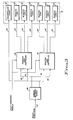
- Fig. 3 depicts the components of a system which can be utilized in accordance with the method of the present invention to adjustably vary the resistive and reactive demand limits of a typical residential circuit to maintain the power factor of the load as close to unity as possible.
- each residential circuit 51 consists of uncontrolled loads 52 which may be both resistive and reactive loads as well as controlled resistive loads 53 and controlled reactive loads 54.
- the resistive loads are controlled by a resistive load controller 55 and the reactive loads are controlled by a reactive load controller 56. Although these are shown as separate load controllers, each of which contain the components of the load controller 36 of Fig.
- incoming power or current from the utility company power buss 57 is sensed 58.
- the power thus sensed is transmitted to the uncontrolled loads 52 through the electrical lines 59 and the power to the controlled loads is transmitted to the resistive load controller 55 through the line 61 and to the reactive load controller 56 through the line 62.
- Metering information is supplied to the load controllers 55 and 56 from the sensor 58 through the lines 63.
- Power is supplied to the resistive loads 53 from the resistive load controller 55 through the lines 64 and power to the reactive 54 is supplied from the reactive load controller 56 through the lines 65.
- the following example illustrates the practice of a method which is a preferred embodiment of the invention in which the utility company is able to maintain a favourable power factor while simultaneously reducing the overall load on its generating facilities. If it is assumed that the residential circuit of Fig. 3 is utilizing power at an instantaneous rate of 10 kw, and that the resistive component of this load is 4 kw and the inductive component is 6 kw, the power factor of this total load is the ratio of the resistive load to the inductive load, i.e., 0.66.
- the utility company can signal a reduction of demand limits on only inductive loads. For example, if the 20% reduction in demand limit is applied only to the inductive loads of the residential circuit 51, causing the system to shed a 2 kw inductive load, then the resistive and inductive loads will be equal and the power factor will be 1.00, the theoretical maximum.
Priority Applications (2)
| Application Number | Priority Date | Filing Date | Title |
|---|---|---|---|
| US06/020,810 US4247786A (en) | 1979-03-15 | 1979-03-15 | Energy management method using utility-generated signals |
| EP80304769A EP0055314A1 (fr) | 1979-03-15 | 1980-12-30 | Gestion d'énergie |
Applications Claiming Priority (2)
| Application Number | Priority Date | Filing Date | Title |
|---|---|---|---|
| US06/020,810 US4247786A (en) | 1979-03-15 | 1979-03-15 | Energy management method using utility-generated signals |
| EP80304769A EP0055314A1 (fr) | 1979-03-15 | 1980-12-30 | Gestion d'énergie |
Publications (1)
| Publication Number | Publication Date |
|---|---|
| EP0055314A1 true EP0055314A1 (fr) | 1982-07-07 |
Family
ID=55268583
Family Applications (1)
| Application Number | Title | Priority Date | Filing Date |
|---|---|---|---|
| EP80304769A Withdrawn EP0055314A1 (fr) | 1979-03-15 | 1980-12-30 | Gestion d'énergie |
Country Status (2)
| Country | Link |
|---|---|
| US (1) | US4247786A (fr) |
| EP (1) | EP0055314A1 (fr) |
Cited By (1)
| Publication number | Priority date | Publication date | Assignee | Title |
|---|---|---|---|---|
| EP0673101A2 (fr) * | 1994-03-18 | 1995-09-20 | Hitachi, Ltd. | Système et méthode de surveillance de distribution d'énergie électrique |
Families Citing this family (74)
| Publication number | Priority date | Publication date | Assignee | Title |
|---|---|---|---|---|
| US4390876A (en) * | 1980-07-25 | 1983-06-28 | Southern California Edison Co., Inc. | Electric utility demand limiting device and method |
| US4583090A (en) * | 1981-10-16 | 1986-04-15 | American Diversified Capital Corporation | Data communication system |
| US4620283A (en) * | 1983-11-29 | 1986-10-28 | Lehigh University | Programmable load controller |
| US4694192A (en) * | 1984-11-23 | 1987-09-15 | Honeywell Inc. | Simplified demand limit control |
| US4819180A (en) * | 1987-02-13 | 1989-04-04 | Dencor Energy Cost Controls, Inc. | Variable-limit demand controller for metering electrical energy |
| AU3150493A (en) * | 1989-09-07 | 1994-06-22 | Lexington Power Management Corporation | Subscriber electric power load control system |
| US5168170A (en) * | 1989-09-07 | 1992-12-01 | Lexington Power Management Corporation | Subscriber electric power load control system |
| US5081402A (en) * | 1991-02-22 | 1992-01-14 | Comfortex Corporation | Low power consumption wireless data transmission and control system |
| US5462225A (en) * | 1994-02-04 | 1995-10-31 | Scientific-Atlanta, Inc. | Apparatus and method for controlling distribution of electrical energy to a space conditioning load |
| US6072858A (en) * | 1996-04-30 | 2000-06-06 | Com/Energy Technologies, Inc. | Method and apparatus for detecting and reporting a defective telecommunications line |
| JP3591300B2 (ja) | 1998-04-24 | 2004-11-17 | 株式会社日立製作所 | 電力供給制御装置 |
| US6529839B1 (en) * | 1998-05-28 | 2003-03-04 | Retx.Com, Inc. | Energy coordination system |
| US20040095237A1 (en) * | 1999-01-09 | 2004-05-20 | Chen Kimball C. | Electronic message delivery system utilizable in the monitoring and control of remote equipment and method of same |
| JP2002118961A (ja) * | 2000-10-04 | 2002-04-19 | Sanyo Electric Co Ltd | 電力負荷管理システム |
| AU2002233162A1 (en) * | 2001-02-15 | 2002-08-28 | Planenergi | Method and system of coordination of consumption and/or production in distribution systems |
| US6828695B1 (en) * | 2001-04-09 | 2004-12-07 | Rick L. Hansen | System, apparatus and method for energy distribution monitoring and control and information transmission |
| US7039575B2 (en) | 2001-04-12 | 2006-05-02 | Ge Capital Services Structured Finance Group, Inc. | Methods and systems for the evaluation of power generating facilities |
| US7265652B2 (en) | 2001-07-10 | 2007-09-04 | Yingco Electronic Inc. | Controllable electronic switch |
| US6832135B2 (en) | 2001-07-10 | 2004-12-14 | Yingco Electronic Inc. | System for remotely controlling energy distribution at local sites |
| US6825750B2 (en) * | 2001-07-10 | 2004-11-30 | Yingco Electronic Inc. | Controllable electronic switch with interposable non-conductive element to break circuit path |
| US7324876B2 (en) | 2001-07-10 | 2008-01-29 | Yingco Electronic Inc. | System for remotely controlling energy distribution at local sites |
| US6861956B2 (en) | 2001-07-10 | 2005-03-01 | Yingco Electronic Inc. | Remotely controllable wireless energy control unit |
| CN101335454B (zh) * | 2001-11-30 | 2012-03-28 | 英科电子有限公司 | 用于远程控制局部站点的能量分配的系统 |
| WO2003049248A2 (fr) * | 2001-11-30 | 2003-06-12 | Yingco Electronic Inc. | Systeme permettant de commander a distance la distribution d'energie a des sites locaux |
| US6631622B1 (en) | 2002-03-22 | 2003-10-14 | Whirlpool Corporation | Demand side management of freezer systems |
| EP1367685A1 (fr) * | 2002-05-31 | 2003-12-03 | Whirlpool Corporation | Système électronique pour la gestion de consommation d'énergie d'appareils |
| EP1372238B1 (fr) * | 2002-06-13 | 2018-06-06 | Whirlpool Corporation | Système global de gestion domestique d'énergie |
| KR100445226B1 (ko) * | 2002-07-24 | 2004-08-21 | 한국전력공사 | 분류형 데이터 구조를 이용한 원격 검침 시스템 |
| US20040083112A1 (en) * | 2002-10-25 | 2004-04-29 | Horst Gale R. | Method and apparatus for managing resources of utility providers |
| DE50212642D1 (de) * | 2002-11-15 | 2008-09-25 | Abb Research Ltd | Konfigurationssystem für Netzwerkgeräte und Verfahren zum Rekonfigurieren von Geräten |
| ES2538484T3 (es) * | 2003-01-21 | 2015-06-22 | Whirlpool Corporation | Un proceso para gestionar y reducir la demanda de potencia de electrodomésticos y componentes de los mismos, y sistema que utiliza dicho proceso |
| AU2003244906A1 (en) * | 2003-06-26 | 2005-01-04 | Key Zoom Technologies De Colombia Ltda. | System for wireless two-way management, measurement and control of the consumption of electrical power and other services |
| US20050194456A1 (en) * | 2004-03-02 | 2005-09-08 | Tessier Patrick C. | Wireless controller with gateway |
| US8704678B2 (en) * | 2005-03-08 | 2014-04-22 | Jackson Kit Wang | Systems and methods for modifying utility usage |
| GB2439490B (en) | 2005-03-08 | 2008-12-17 | Radio Usa Inc E | Systems and methods for modifying power usage |
| US8615332B2 (en) * | 2005-06-09 | 2013-12-24 | Whirlpool Corporation | Smart current attenuator for energy conservation in appliances |
| US8027752B2 (en) * | 2005-06-09 | 2011-09-27 | Whirlpool Corporation | Network for changing resource consumption in an appliance |
| KR200403816Y1 (ko) * | 2005-09-29 | 2005-12-14 | 임정도 | 피엘씨를 이용한 전자동 절전장치 |
| US7580775B2 (en) * | 2006-07-11 | 2009-08-25 | Regen Energy Inc. | Method and apparatus for implementing enablement state decision for energy consuming load based on demand and duty cycle of load |
| US8527108B2 (en) | 2006-07-11 | 2013-09-03 | Regen Energy Inc. | Method and apparatus for managing an energy consuming load |
| US8527109B2 (en) * | 2006-07-11 | 2013-09-03 | Regen Energy Inc. | Method and apparatus for managing an energy consuming load |
| US7705484B2 (en) * | 2007-04-10 | 2010-04-27 | Whirlpool Corporation | Energy management system and method |
| US8541719B2 (en) * | 2008-09-15 | 2013-09-24 | General Electric Company | System for reduced peak power consumption by a cooking appliance |
| US8548638B2 (en) * | 2008-09-15 | 2013-10-01 | General Electric Company | Energy management system and method |
| WO2010031028A1 (fr) * | 2008-09-15 | 2010-03-18 | General Electric Company | Gestion d'énergie d’appareils électroménagers |
| US8803040B2 (en) * | 2008-09-15 | 2014-08-12 | General Electric Company | Load shedding for surface heating units on electromechanically controlled cooking appliances |
| US9303878B2 (en) | 2008-09-15 | 2016-04-05 | General Electric Company | Hybrid range and method of use thereof |
| US8843242B2 (en) * | 2008-09-15 | 2014-09-23 | General Electric Company | System and method for minimizing consumer impact during demand responses |
| WO2010042200A1 (fr) * | 2008-10-08 | 2010-04-15 | Rey Montalvo | Procédé et système pour une réduction de consommation d'énergie entièrement automatisée |
| US9002761B2 (en) | 2008-10-08 | 2015-04-07 | Rey Montalvo | Method and system for automatically adapting end user power usage |
| EP2345131B1 (fr) * | 2008-10-20 | 2019-01-30 | Deborah Lynn Fallis | Systeme et procede de correction de facteur de puissance monophase |
| US8010240B2 (en) * | 2008-11-25 | 2011-08-30 | International Business Machines Corporation | Method and system for electricity consumption profile management for consumer devices |
| US9665838B2 (en) * | 2008-12-03 | 2017-05-30 | Whirlpool Corporation | Messaging architecture and system for electronic management of resources |
| US20100207728A1 (en) * | 2009-02-18 | 2010-08-19 | General Electric Corporation | Energy management |
| US8522579B2 (en) * | 2009-09-15 | 2013-09-03 | General Electric Company | Clothes washer demand response with dual wattage or auxiliary heater |
| US8869569B2 (en) * | 2009-09-15 | 2014-10-28 | General Electric Company | Clothes washer demand response with at least one additional spin cycle |
| US8943845B2 (en) | 2009-09-15 | 2015-02-03 | General Electric Company | Window air conditioner demand supply management response |
| US8943857B2 (en) * | 2009-09-15 | 2015-02-03 | General Electric Company | Clothes washer demand response by duty cycling the heater and/or the mechanical action |
| US8386087B2 (en) * | 2010-08-02 | 2013-02-26 | General Electric Company | Load shed system for demand response without AMI/AMR system |
| US8801862B2 (en) | 2010-09-27 | 2014-08-12 | General Electric Company | Dishwasher auto hot start and DSM |
| US8869546B2 (en) | 2010-11-03 | 2014-10-28 | General Electric Company | Refrigeration demand response recovery |
| US8423198B2 (en) | 2010-11-30 | 2013-04-16 | General Electric Company | Energy response management—time of day method |
| US8234018B2 (en) | 2010-12-16 | 2012-07-31 | General Electric Company | Energy management of appliance cycle longer than low rate period |
| US8423194B2 (en) | 2011-03-08 | 2013-04-16 | General Electric Company | Generator demand response behavior |
| US20120053741A1 (en) | 2011-03-08 | 2012-03-01 | General Electric Company | Manage whole home appliances/loads to a peak energy consumption |
| US20130008893A1 (en) * | 2011-07-08 | 2013-01-10 | General Electric Company | Energy management in a microwave cooking appliance |
| PL2898580T3 (pl) | 2012-09-21 | 2018-01-31 | Philips Lighting Holding Bv | Automatyczne przycinanie poziomu mocy poprzez nośnik transmisji |
| US20140316958A1 (en) * | 2013-04-17 | 2014-10-23 | Green Edge Technologies, Inc. | Systems, devices, and methods for energy account management |
| CA2998101C (fr) * | 2014-09-08 | 2022-12-06 | Christopher Robert Debone | Energie intermittente, distribuee, adaptative en temps reel et reliee au reseau |
| US10605474B2 (en) | 2015-07-30 | 2020-03-31 | Encycle Corporation | Smart thermostat orchestration |
| US11031787B2 (en) | 2018-09-14 | 2021-06-08 | Lancium Llc | System of critical datacenters and behind-the-meter flexible datacenters |
| US11907029B2 (en) | 2019-05-15 | 2024-02-20 | Upstream Data Inc. | Portable blockchain mining system and methods of use |
| US11868106B2 (en) | 2019-08-01 | 2024-01-09 | Lancium Llc | Granular power ramping |
| DE102022203456A1 (de) | 2022-04-06 | 2023-10-12 | Bob Patent Gmbh | Netzschonendes Lastmanagement für eine Wärmepumpe |
Citations (3)
| Publication number | Priority date | Publication date | Assignee | Title |
|---|---|---|---|---|
| DE2404234A1 (de) * | 1974-01-30 | 1975-08-07 | Licentia Gmbh | Anordnung zur lastverteilung in niederspannungsnetzen |
| EP0020310A1 (fr) * | 1979-05-28 | 1980-12-10 | Arnaldo Spena | Dispositif de commande à distance pour la surveillance des conditions de charge du réseau électrique |
| FR2464588A1 (fr) * | 1979-08-31 | 1981-03-06 | Alberti Rosette | Reseau de distribution electrique avec telereglage des disjoncteurs de puissance |
Family Cites Families (3)
| Publication number | Priority date | Publication date | Assignee | Title |
|---|---|---|---|---|
| US4023043A (en) * | 1974-08-16 | 1977-05-10 | Megatherm Corporation | Computerized peak-shaving system for alleviating electric utility peak loads |
| US4125782A (en) * | 1977-02-15 | 1978-11-14 | Allen-Bradley Company | Demand/schedule controller |
| US4152605A (en) * | 1977-10-03 | 1979-05-01 | Conde Hector O | Automatic load control system and method for a power distribution network |
-
1979
- 1979-03-15 US US06/020,810 patent/US4247786A/en not_active Expired - Lifetime
-
1980
- 1980-12-30 EP EP80304769A patent/EP0055314A1/fr not_active Withdrawn
Patent Citations (3)
| Publication number | Priority date | Publication date | Assignee | Title |
|---|---|---|---|---|
| DE2404234A1 (de) * | 1974-01-30 | 1975-08-07 | Licentia Gmbh | Anordnung zur lastverteilung in niederspannungsnetzen |
| EP0020310A1 (fr) * | 1979-05-28 | 1980-12-10 | Arnaldo Spena | Dispositif de commande à distance pour la surveillance des conditions de charge du réseau électrique |
| FR2464588A1 (fr) * | 1979-08-31 | 1981-03-06 | Alberti Rosette | Reseau de distribution electrique avec telereglage des disjoncteurs de puissance |
Cited By (2)
| Publication number | Priority date | Publication date | Assignee | Title |
|---|---|---|---|---|
| EP0673101A2 (fr) * | 1994-03-18 | 1995-09-20 | Hitachi, Ltd. | Système et méthode de surveillance de distribution d'énergie électrique |
| EP0673101A3 (fr) * | 1994-03-18 | 1997-12-10 | Hitachi, Ltd. | Système et méthode de surveillance de distribution d'énergie électrique |
Also Published As
| Publication number | Publication date |
|---|---|
| US4247786A (en) | 1981-01-27 |
Similar Documents
| Publication | Publication Date | Title |
|---|---|---|
| US4247786A (en) | Energy management method using utility-generated signals | |
| RU2431172C2 (ru) | Гибкая система управления электрической нагрузкой и способ ее работы | |
| US5696695A (en) | System for rate-related control of electrical loads | |
| EP2041853B1 (fr) | Dispositif de contrôle de charges pour installation électrique domestique | |
| EP2416465B1 (fr) | Système de délestage pour réponse de demande sans système AMI/AMR | |
| US4245319A (en) | Energy management method and apparatus utilizing duty cycle reduction synchronized with the zero points of the applied voltage | |
| EP0886362B1 (fr) | Système de contrôle pour la distribution d'énergie | |
| CN1883094B (zh) | 连接到电力负载的响应负载装置及控制电力负载的方法 | |
| AU711943B2 (en) | Apparatus for and method of evenly distributing an electrical load across a three-phase power distribution network | |
| EP1372238B1 (fr) | Système global de gestion domestique d'énergie | |
| US6493643B1 (en) | Method for the energy management in a domestic environment | |
| Wacks | Utility load management using home automation | |
| US20010010032A1 (en) | Energy management and building automation system | |
| US20090024545A1 (en) | Method and system for measurement and control of individual circuits | |
| JPH11313441A (ja) | 家庭内電力dsmシステム | |
| CN105359368A (zh) | 用于控制电气网络中的功率负载的设备及相关的方法和系统 | |
| EP0717487B1 (fr) | Système électrique avec commande de la demande en puissance | |
| US20230291206A1 (en) | Energy management system and method | |
| CA1098996A (fr) | Traduction non-disponible | |
| IL191442A (en) | Flexible load management system and method for it | |
| Energy | On–Line Demand Management of Low Voltage Residential Distribution Networks in Smart Grids | |
| IES85092Y1 (en) | A load management controller for a household electrical installation | |
| IE20080290U1 (en) | A load management controller for a household electrical installation |
Legal Events
| Date | Code | Title | Description |
|---|---|---|---|
| PUAI | Public reference made under article 153(3) epc to a published international application that has entered the european phase |
Free format text: ORIGINAL CODE: 0009012 |
|
| AK | Designated contracting states |
Designated state(s): AT CH DE FR GB SE |
|
| 17P | Request for examination filed |
Effective date: 19821216 |
|
| STAA | Information on the status of an ep patent application or granted ep patent |
Free format text: STATUS: THE APPLICATION IS DEEMED TO BE WITHDRAWN |
|
| 18D | Application deemed to be withdrawn |
Effective date: 19850226 |
|
| RIN1 | Information on inventor provided before grant (corrected) |
Inventor name: HEDGES, WALTER P. |