EP0055020A2 - Bremsfingerhebel für Angelwinde und Montageverfahren dafür - Google Patents
Bremsfingerhebel für Angelwinde und Montageverfahren dafür Download PDFInfo
- Publication number
- EP0055020A2 EP0055020A2 EP81305283A EP81305283A EP0055020A2 EP 0055020 A2 EP0055020 A2 EP 0055020A2 EP 81305283 A EP81305283 A EP 81305283A EP 81305283 A EP81305283 A EP 81305283A EP 0055020 A2 EP0055020 A2 EP 0055020A2
- Authority
- EP
- European Patent Office
- Prior art keywords
- leg
- lever
- reel
- brake lever
- bellcrank
- Prior art date
- Legal status (The legal status is an assumption and is not a legal conclusion. Google has not performed a legal analysis and makes no representation as to the accuracy of the status listed.)
- Withdrawn
Links
Images
Classifications
-
- A—HUMAN NECESSITIES
- A01—AGRICULTURE; FORESTRY; ANIMAL HUSBANDRY; HUNTING; TRAPPING; FISHING
- A01K—ANIMAL HUSBANDRY; AVICULTURE; APICULTURE; PISCICULTURE; FISHING; REARING OR BREEDING ANIMALS, NOT OTHERWISE PROVIDED FOR; NEW BREEDS OF ANIMALS
- A01K89/00—Reels
-
- B—PERFORMING OPERATIONS; TRANSPORTING
- B29—WORKING OF PLASTICS; WORKING OF SUBSTANCES IN A PLASTIC STATE IN GENERAL
- B29C—SHAPING OR JOINING OF PLASTICS; SHAPING OF MATERIAL IN A PLASTIC STATE, NOT OTHERWISE PROVIDED FOR; AFTER-TREATMENT OF THE SHAPED PRODUCTS, e.g. REPAIRING
- B29C65/00—Joining or sealing of preformed parts, e.g. welding of plastics materials; Apparatus therefor
- B29C65/66—Joining or sealing of preformed parts, e.g. welding of plastics materials; Apparatus therefor by liberation of internal stresses, e.g. shrinking of one of the parts to be joined
- B29C65/665—Joining or sealing of preformed parts, e.g. welding of plastics materials; Apparatus therefor by liberation of internal stresses, e.g. shrinking of one of the parts to be joined using shrinking during cooling
-
- A—HUMAN NECESSITIES
- A01—AGRICULTURE; FORESTRY; ANIMAL HUSBANDRY; HUNTING; TRAPPING; FISHING
- A01K—ANIMAL HUSBANDRY; AVICULTURE; APICULTURE; PISCICULTURE; FISHING; REARING OR BREEDING ANIMALS, NOT OTHERWISE PROVIDED FOR; NEW BREEDS OF ANIMALS
- A01K89/00—Reels
- A01K89/02—Brake devices for reels
- A01K89/027—Brake devices for reels with pick-up, i.e. for reels with the guiding member rotating and the spool not rotating during normal retrieval of the line
- A01K89/0275—Brake devices for reels with pick-up, i.e. for reels with the guiding member rotating and the spool not rotating during normal retrieval of the line with closed face
-
- B—PERFORMING OPERATIONS; TRANSPORTING
- B29—WORKING OF PLASTICS; WORKING OF SUBSTANCES IN A PLASTIC STATE IN GENERAL
- B29L—INDEXING SCHEME ASSOCIATED WITH SUBCLASS B29C, RELATING TO PARTICULAR ARTICLES
- B29L2031/00—Other particular articles
- B29L2031/748—Machines or parts thereof not otherwise provided for
- B29L2031/7482—Brakes
-
- Y—GENERAL TAGGING OF NEW TECHNOLOGICAL DEVELOPMENTS; GENERAL TAGGING OF CROSS-SECTIONAL TECHNOLOGIES SPANNING OVER SEVERAL SECTIONS OF THE IPC; TECHNICAL SUBJECTS COVERED BY FORMER USPC CROSS-REFERENCE ART COLLECTIONS [XRACs] AND DIGESTS
- Y10—TECHNICAL SUBJECTS COVERED BY FORMER USPC
- Y10S—TECHNICAL SUBJECTS COVERED BY FORMER USPC CROSS-REFERENCE ART COLLECTIONS [XRACs] AND DIGESTS
- Y10S242/00—Winding, tensioning, or guiding
- Y10S242/90—Particular apparatus material
-
- Y—GENERAL TAGGING OF NEW TECHNOLOGICAL DEVELOPMENTS; GENERAL TAGGING OF CROSS-SECTIONAL TECHNOLOGIES SPANNING OVER SEVERAL SECTIONS OF THE IPC; TECHNICAL SUBJECTS COVERED BY FORMER USPC CROSS-REFERENCE ART COLLECTIONS [XRACs] AND DIGESTS
- Y10—TECHNICAL SUBJECTS COVERED BY FORMER USPC
- Y10T—TECHNICAL SUBJECTS COVERED BY FORMER US CLASSIFICATION
- Y10T29/00—Metal working
- Y10T29/49—Method of mechanical manufacture
- Y10T29/49826—Assembling or joining
- Y10T29/49863—Assembling or joining with prestressing of part
- Y10T29/49865—Assembling or joining with prestressing of part by temperature differential [e.g., shrink fit]
Definitions
- This application relates to a closed face spinning reel and more particularly to a finger brake, for such a reel and to a method of assembling the finger brake.
- a closed face spinning reel of the character considered herein is mounted below a fishing rod at the butt of the handle.
- a typical reel has a body with an axially movable shaft on which a spinner head is mounted. The shaft is biased rearwardly in the reel body to a line winding position.
- a finger brake lever actuated by the fisherman moves the shaft and spinner head forward to casting and brake positions.
- Copending Miller U.S. application SN 112912 filed January 17, 1980 shows a reel with a twisted finger brake that projects forwardly adjacent the rod handle for actuation by the fisherman. The twisted finger brake is pivoted to the reel body and is free to move with respect to the body and to the axial shaft.
- Special guide structure is provided to maintain alignment of the operating leg of the lever with the end of the shaft.
- the lever is free to move when it is not actuated by the fisherman.
- the operating handle is not in a uniform or fixed position with respect to the rod and the fisherman cannot reliably grip and operate it.
- the lever rattles which may be disturbing to the fisherman.
- the reel of the present application is directed to overcoming one or more of the problems as set forth above.
- the finger brake is provided with resilient means for urging the lever to a stop position with the operating leg of the lever out of contact with the reel shaft. This minimizes rattling of the lever and locates the finger grip in a uniform position when released.
- the lever has a finger grip portion which is a molded plastic part and includes a flexible element molded integrally therewith which bears against a surface of the reel body to urge the element to the stop position.
- a surface of the molded plastic part engages the reel body to define the stop position for the lever.
- the molded plastic part has a slot therein which receives a leg of an element as the lever.
- the leg has a portion with a dimension greater than the corresponding dimension of the slot and a section adjacent such portion and remote from the end of the leg with a smaller dimension.
- the plastic cover is molded with the slot therein at a temperature above the ambient where the plastic material is flowable.
- the leg of the element is inserted into the slot while the plastic material remains warm from the molding operation so that the plastic material expands over the portion of greater dimension and, upon cooling, shrinks to an interference fit or interlock with the leg.
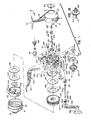
- Figure 1 generally depicts an exploded perspective view of a fishing'reel 10 of the spin casting type containing the preferred.embodiment of the invention.
- a back support housing 11 preferably made of an aluminum alloy material, has a cylindrical-cover 12, one end of which is open and the other end of which merges into a semispherical rear wall 13 having a center opening 14 in which is seated a back cap 15.
- a stem 16 is integrally cast with the cylindrical cover 12 and has a mounting foot 17 which is used to attach the reel 10 to a spinning style fishing rod (not shown).
- a body 20, made of a plastic material, such as a glass filled polycarbonate, has a transverse deck plate 21 with a first or forward circumferential body portion 22 and a second or rearward circumferential body portion 23.
- a central hub 24 projects forward of the deck plate 21 with a drag plate 210, back spool washer 230, back flat drag washer 233, spool assembly 130, front flat drag washer 235, front spool washer 237, all secured to the hub 24 by means of spool retainer clip 240 which fits into a groove (not shown in Figure 1) in the distal end of hub 24.
- the body 20 is secured to the back support housing 11 by inserting an inset flange 26 on the rearward body portion 23 of the body 20 into the one open end of the cylindrical cover 12 of the back support housing 11 and threading screws 27, only one of which is shown in Figure 1, through apertures 28 in bosses 29 formed through and on the deck plate 21 and into mating bosses (not shown in Figure 1) in the back support housing 11.
- a front cover 90 which has a cylindrical body portion 91 and a cone-shaped front portion 92, is secured on an offset portion 30 of the forward body portion 22.
- a center shaft 251 is mounted in a center hole (not shown in Figure 1) in the hub 24 with a spinner head assembly 242 threaded by means of the threaded opening 250 on the forward threaded end of the shaft 251.
- the spinner head assembly 242 partially surrounds the forward flange of the spool assembly 130 with fishing line 99 being wound thereon.
- the cone-shaped front portion 92 of the front cover 90 has a front hole (not shown in Figure 1) which acts as a fishing line guide as the line 99 is cast from the reel 10 and rewound after casting.
- a clutch head screw 201 passes through a pilot hole or guide (not shown in Figure 1) in the deck plate 21 with the slotted head of the screw positioned in the interior of the forward body portion 22 and with a clutch wheel 204 projecting outward of a slot 25 in the rearward body portion 23 threadingly engaging with the body of the clutch head screw 201 where the screw porjects into said rearward body portion 23.
- a tab 217 on the drag plate 210 fits into the head of screw 201 so that when the clutch wheel 204 is revolved upward toward stem 16, the screw 201 advances forward toward the spool retainer clip 240, increasing the clamping force on the spool assembly 130 so that the ability of the spool assembly 130 to revolve relative to the hub 24 is decreased.
- the clutch wheel 204 is revolved away from the stem 16, the clamping force is decreased and the spool assembly 130 is permitted to revolve more freely relative to hub 24, thus providing the adjustable drag mechanism for the fishing reel 10.
- the center shaft 251 is slidably and rotatably mounted in a bearing 269 which is mounted in the rear of the hub 24 in the deck plate 21.
- a pinion gear 260 is splined on a reduced diameter portion 252 of the center shaft 251 and is resiliently maintained in a forward position against the deck plate 21 by a cwnter shaft spring 265.
- the pinion gear 260 and center shaft 251, being splined together, will have relative axial sliding motion, but rotation of the pinion gear_260 will rotate the center shaft 251.
- the spring 265 bears against an abutting end 255 on the center shaft 251 to urge the pinion gear 260 against the deck plate 21 and to urge the center shaft 251 in a rearward direction relative to the deck plate 21.
- ... -A finger brake lever 300 is mounted on the body 20 with an operating handle 301 exterior of and extending forwardly from the first or forward body portion 22.
- An operating leg 302 extends through a slot 303 in an upstanding bracket 304 on the body 20 and into the second or rearward body portion 23 for operable contact with the rearward end 255 of the center shaft 251.
- operating leg 302 engages the end 255 of the center shaft 251.
- the center shaft 250 and the spinner head assembly 242 mounted thereon are pushed forward relative to the bearing 269 and the hub 24.
- a pickup pin mechanism 243 mounted on and within spinner head assembly 242, is, at this point, in retracted position and cooperates with a forward face of a cam (not shown in Figure 1) carried by the face of the hub 24.
- a cam not shown in Figure 1
- the finger brake lever 300 When the finger brake lever 300 is fully pivoted toward the mounting foot 17, the spinner head assembly 242 is held in a brake position against the inside of the front cover 90 to trap the line 99 therebetween to prevent casting of the line. Slightly releasing the finger brake lever 300 will maintain the spinner head assembly 242 in a forward casting position, but the spring 265 will retract the center shaft 251 and the spinner head assembly 242 enough to unclamp the fishing line 99 whereby the spinner head assembly 242 will not interfere with the fishing line 99 which can then be cast freely from the reel 10.
- a crank assembly 310 is mounted in transversely extending hollow bearing bosses 39 and 40 integrally formed on the wall of the rearward body portion 23.
- Crank bearing sleeve means 160 and 161 are mounted respectively in the bearing bosses 39 and 40 to provide suitable bearings for a hollow crankshaft 311 of the crank assembly 310.
- the hollow crankshaft 311 supports an antireverse assembly 330 which will be described in more detail hereinafter.
- a crank rod 331 is pivotally connected to a crank handle 332 by means of a pin 332a and the crank rod 331 is slip-fitted into the hollow crankshaft 311 and has flats 331a which mate with flats in the hollow crankshaft 311 to key the crankshaft 311 thereto.
- a fitting 333 which slides on the crank rod 331 inwardly of the pin 332a has an outer portion 333a that slides easily into one of the bosses 39 or 40 and has an inner portion 333b of smaller diameter which slides easily into the outer end of one of the crank bearing sleeve means 160 or 161.
- a crank rod nut 334 is secured to a threaded end 335 of the crank rod 331 to fasten said rod 331 to the reel 10.
- crank rod 331 can be removed from the side of the reel 10 that it occupies in Figure 1, and mounted in the opposite side by unfastening the nut 334 in sleeve means 161, removing the crank handle 332 and crank rod 331 from the hollow boss 39, inserting the crank rod 331 in the hollod boss 40, and refastening the nut 334 on the end of the rod in the sleeve means 160.
- the crank handle 332 has a crank know 332b for gripping by the hand of the user.
- a face gear 313 Fixed to the hollow crankshaft 311 is a face gear 313 which is in engageable contact with the pinion gear 260 on the shaft 251 so that when the crank handle 332 is rotated in a forward direction (toward the front cover 90 as viewed in Figure 1), the shaft 251 rotates causing the spinner head assembly 242 to rotate as well.
- This rotative motion disengages the pickup pin mechanism 243 from the forward face of the cam on the hub 24, causing the spinner head assembly 242 to move rearward as the pickup pin mechanism 243 rides up the cam to extend the pickup pin 245 outwardly beyond the spinner head assembly 242 so that the rotation of the crank handle 332 will rotate the spinner head assembly 242 to wind the fishing line 99 on the spool assembly 130.
- Crank assembly 310 is coupled with an antireverse assembly 330, which comprises a ratchet 336, mounted on the crankshaft 311 against the back side of face gear 313 as shown in Figure l(a), an antireverse drag arm 337 having a transverse lug 338, a drag spring 339 and spacer washer 340 all mounted on the hollow crankshaft 311.
- An antireverse pawl 341 having a pivot tang 342 pivotably mounted in an aperture 343 in the deck plate 21, is positioned against the back of the face gear 313 between the deck plate 2 1 and the transverse lug 338 on the drag arm 337 for engageable and disengageable contact with the ratchet 336.
- Antireverse actuator 150 is mounted in upper housing sleeve 60 that opens through the wall of the rearward body portion 23 of body 20 and the actuator 150 is retained in the sleeve 60 by retainer clip 170 seated in slot 171 in the body of the antireverse actuator 150.
- the antireverse actuator 150 is in cooperative contact, as will be described hereinafter, with the antireverse drag arm 317. In one position, the actuator 150 disengages the antireverse assembly 330 permitting the crank rod 331 and the crank assembly to rotate in either the forward direction (upward toward the stem 16) or the reverse direction (downward from the stem 16 toward the back of the reel 10). In the other position of the actuator 150, the crank assembly can rotate to wind the line 99 on the spool 130.
- Figure 2 shows the reel assembled but with the crank handle 332 extending from the right side of the body 20 rather than from the left as in Figure 1.
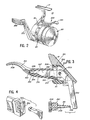
- the mounting foot 17 is secured to the butt of the handle of a fishing rod (not shown) so that the fisherman may hold the rod and actuate the brake lever 300 by manipulating handle 301 with a finger of the hand which holds the rod.
- Bracket 304 is integral with reel body 20 and extends outwardly therefrom.
- the bracket has two laterally spaced apart bracket members, one of which is seen at 305 in Figure 3.
- Slot 303 is defined by the facing surfaces of the two bracket members.
- the bracket is seated in a recess 306 in the forward wall of stem 16.
- the brake lever is preferably stamped of sheet metal and has a bellcrank configuration with an operating leg 302 and a leg 307 on which cover or operator handle 301 is mounted,having a finger grip portion 308.
- the brake lever is pivotally mounted on pin 309 extending between the legs 305 of bracket 304.
- Operating leg 302 extends into the reel with its end immediately to the rear of the rear end 255 of shaft 251.
- Leg 307 and handle 301 extend forwardly between the reel body and the handle of the fishing rod.
- Handle 301 is preferably molded of the plastic material and has a pair of cantilevered resilient elements 350 formed at its inner end and adjacent pivot pin 309 with the handle assembled with the bellcrank lever.
- the resilient elements 350 lie on either side of lever leg 307, extending upwardly as seen in Figure 3. With the bellcrank lever assembled to the reel body, the resilient elements engage the forwardly facing surfaces 351 of the bracket members 305, one of which is seen in Figure 3.
- the resilience of the elements 350 urge the brake lever counterclockwise as viewed in Figure 3 with the end of the leg 302 out of contact with the rear end 255 of shaft 251.
- the fisherman by lifting handle 301 pivots the bellcrank against the resilient force of elements 350 and brings the end of leg 302 into engagement with the end 255 of shaft 251.
- the thickness of operating leg 302 is preferably equal to or greater than the diameter of shaft end 255.
- the width of slot 303 is slightly greater than the thickness of the bellcrank to permit pivotal movement without binding but not so great as to allow significant lateral movement or canting of the brake lever.
- Handle 301 has a surface 352 which engages reel body 20 to limit counterclockwise movement of the brake lever, defining the stop position of the brake lever.
- the finger grip portion 308 when released, has a fixed location with respect to the rod handle so the fisherman may reliably reach for and actuate the brake.
- Leg 307 of the bellcrank has a portion 353 at the end thereof which is wider than the adjacent section 354 of the leg, with surfaces 355 which face away from the end of the leg and are interlocked with the cover 301 holding it on the leg.
- the cover is preferably molded of plastic, as an ABS resin or nylon.
- a slot is molded in the cover with a dimension seen vertically in Figure 3 which is slightly smaller than the . width of the end portion 353 of the lever leg.
Landscapes
- Life Sciences & Earth Sciences (AREA)
- Environmental Sciences (AREA)
- Animal Husbandry (AREA)
- Biodiversity & Conservation Biology (AREA)
- Engineering & Computer Science (AREA)
- Mechanical Engineering (AREA)
Applications Claiming Priority (2)
| Application Number | Priority Date | Filing Date | Title |
|---|---|---|---|
| US06/218,926 US4382562A (en) | 1980-12-22 | 1980-12-22 | Finger brake for a spinning reel and method of assembling same |
| US218926 | 1980-12-22 |
Publications (2)
| Publication Number | Publication Date |
|---|---|
| EP0055020A2 true EP0055020A2 (de) | 1982-06-30 |
| EP0055020A3 EP0055020A3 (de) | 1982-10-27 |
Family
ID=22817051
Family Applications (1)
| Application Number | Title | Priority Date | Filing Date |
|---|---|---|---|
| EP81305283A Withdrawn EP0055020A3 (de) | 1980-12-22 | 1981-11-06 | Bremsfingerhebel für Angelwinde und Montageverfahren dafür |
Country Status (5)
| Country | Link |
|---|---|
| US (1) | US4382562A (de) |
| EP (1) | EP0055020A3 (de) |
| JP (1) | JPS57163426A (de) |
| KR (1) | KR830006871A (de) |
| CA (1) | CA1170236A (de) |
Families Citing this family (4)
| Publication number | Priority date | Publication date | Assignee | Title |
|---|---|---|---|---|
| JPH01146375U (de) * | 1988-03-31 | 1989-10-09 | ||
| US5437297A (en) * | 1992-10-30 | 1995-08-01 | Sunbeam Corporation | Crank handle assembly for use in an umbrella |
| US6056221A (en) * | 1998-11-10 | 2000-05-02 | Brunswick Corporation | Fishing reel with trigger actuated bail assembly |
| CN106259232B (zh) * | 2016-09-22 | 2022-07-08 | 宁波中源欧佳渔具股份有限公司 | 双碟式活动手刹渔线轮 |
Family Cites Families (9)
| Publication number | Priority date | Publication date | Assignee | Title |
|---|---|---|---|---|
| US2705336A (en) * | 1948-12-03 | 1955-04-05 | Illinois Duster & Brush Co | Cleaning instrument having a detachable handle provided with a cap |
| US2520808A (en) * | 1948-12-11 | 1950-08-29 | Robert J Miller | Grip for pliers |
| US2929579A (en) * | 1956-08-23 | 1960-03-22 | Hull R Dell | Underslung spinning reel |
| GB822851A (en) * | 1957-06-03 | 1959-11-04 | Geo F Ball And Company Ltd | Fishing reels |
| US3085766A (en) * | 1959-03-11 | 1963-04-16 | Fishing Tackle Company Of Amer | Spinning type fishing reel |
| US3018979A (en) * | 1959-05-15 | 1962-01-30 | Shakespeare Co | Level wind fishing reel |
| US3142454A (en) * | 1961-05-04 | 1964-07-28 | Hull R Dell | Spinning reel with line brake |
| US3381914A (en) * | 1965-11-30 | 1968-05-07 | John K. Taggart | Spinning reel with brake |
| US4154413A (en) * | 1973-11-01 | 1979-05-15 | Hull R Dell | Closed face spinning reel |
-
1980
- 1980-12-22 US US06/218,926 patent/US4382562A/en not_active Expired - Lifetime
-
1981
- 1981-11-04 CA CA000389443A patent/CA1170236A/en not_active Expired
- 1981-11-06 EP EP81305283A patent/EP0055020A3/de not_active Withdrawn
- 1981-12-10 KR KR1019810004839A patent/KR830006871A/ko not_active Withdrawn
- 1981-12-22 JP JP56207954A patent/JPS57163426A/ja active Pending
Also Published As
| Publication number | Publication date |
|---|---|
| US4382562A (en) | 1983-05-10 |
| CA1170236A (en) | 1984-07-03 |
| EP0055020A3 (de) | 1982-10-27 |
| JPS57163426A (en) | 1982-10-07 |
| KR830006871A (ko) | 1983-10-12 |
Similar Documents
| Publication | Publication Date | Title |
|---|---|---|
| CA1166224A (en) | Selective anti-reverse mechanism | |
| CA1154002A (en) | Two-part front cover for spin cast reels | |
| US6138935A (en) | Two piece cover for fishing reel | |
| US6089484A (en) | Bushing for fishing reels | |
| US6070822A (en) | Hook retainer for fishing reel | |
| US4382562A (en) | Finger brake for a spinning reel and method of assembling same | |
| US9288973B1 (en) | Thumb button for fishing reels | |
| EP0055022A2 (de) | Angelwinde | |
| US6641070B1 (en) | Spincast fishing reel having multipiece rear cover assembly | |
| US4359197A (en) | Silent-selective anti-reverse mechanism | |
| US4332358A (en) | Spin casting type fishing reel with improved dual crank bearing retention means | |
| US20050189446A1 (en) | Rotor for spinning reel | |
| CA1170238A (en) | Folding crank handle for a fishing reel | |
| EP1354514B1 (de) | Befestigungsstruktur einer Schneckenwelle für Angelrolle | |
| US3970263A (en) | Ruggedized closed face spinning reel | |
| US10939674B1 (en) | Bearing supported pick-up pin for spincast reel | |
| US7178751B1 (en) | Fishing reel | |
| US4359196A (en) | Spinning reel housing with an access opening and removable cap therefor | |
| US4824040A (en) | Quick bail opening system for fishing reel | |
| US5740976A (en) | One-piece fishing reel subassembly | |
| CA1164427A (en) | Back support housing and reel body assembly | |
| CA1173418A (en) | Snap-in anti-reverse selector | |
| US3900167A (en) | Closed face spinning reel | |
| US5004182A (en) | Convertible bail opening system | |
| CA1155100A (en) | Trip lever guide system |
Legal Events
| Date | Code | Title | Description |
|---|---|---|---|
| PUAI | Public reference made under article 153(3) epc to a published international application that has entered the european phase |
Free format text: ORIGINAL CODE: 0009012 |
|
| AK | Designated contracting states |
Designated state(s): DE FR GB IT SE |
|
| PUAL | Search report despatched |
Free format text: ORIGINAL CODE: 0009013 |
|
| AK | Designated contracting states |
Designated state(s): DE FR GB IT SE |
|
| 17P | Request for examination filed |
Effective date: 19830329 |
|
| STAA | Information on the status of an ep patent application or granted ep patent |
Free format text: STATUS: THE APPLICATION IS DEEMED TO BE WITHDRAWN |
|
| 18D | Application deemed to be withdrawn |
Effective date: 19840814 |
|
| RIN1 | Information on inventor provided before grant (corrected) |
Inventor name: NEUFELD, HENRY L. |