EP0054584A1 - Breitbandantennensystem - Google Patents
Breitbandantennensystem Download PDFInfo
- Publication number
- EP0054584A1 EP0054584A1 EP80201214A EP80201214A EP0054584A1 EP 0054584 A1 EP0054584 A1 EP 0054584A1 EP 80201214 A EP80201214 A EP 80201214A EP 80201214 A EP80201214 A EP 80201214A EP 0054584 A1 EP0054584 A1 EP 0054584A1
- Authority
- EP
- European Patent Office
- Prior art keywords
- draw
- aerial
- view
- elements
- type
- Prior art date
- Legal status (The legal status is an assumption and is not a legal conclusion. Google has not performed a legal analysis and makes no representation as to the accuracy of the status listed.)
- Withdrawn
Links
- 230000003068 static effect Effects 0.000 claims 1
- 229920002994 synthetic fiber Polymers 0.000 claims 1
- 238000010276 construction Methods 0.000 description 6
- 239000000463 material Substances 0.000 description 3
- 101100282617 Bovine herpesvirus 1.1 (strain Cooper) gC gene Proteins 0.000 description 2
- 229910052782 aluminium Inorganic materials 0.000 description 2
- 239000003822 epoxy resin Substances 0.000 description 2
- 229920000647 polyepoxide Polymers 0.000 description 2
- 101100515516 Arabidopsis thaliana XI-H gene Proteins 0.000 description 1
- 101100515517 Arabidopsis thaliana XI-I gene Proteins 0.000 description 1
- 101100515520 Arabidopsis thaliana XI-J gene Proteins 0.000 description 1
- 229910001369 Brass Inorganic materials 0.000 description 1
- RYGMFSIKBFXOCR-UHFFFAOYSA-N Copper Chemical compound [Cu] RYGMFSIKBFXOCR-UHFFFAOYSA-N 0.000 description 1
- 206010061619 Deformity Diseases 0.000 description 1
- 229910000737 Duralumin Inorganic materials 0.000 description 1
- 229910000639 Spring steel Inorganic materials 0.000 description 1
- 230000003321 amplification Effects 0.000 description 1
- 239000010951 brass Substances 0.000 description 1
- 238000005266 casting Methods 0.000 description 1
- 229910052802 copper Inorganic materials 0.000 description 1
- 239000010949 copper Substances 0.000 description 1
- 238000009434 installation Methods 0.000 description 1
- 238000012423 maintenance Methods 0.000 description 1
- 238000004519 manufacturing process Methods 0.000 description 1
- 238000000034 method Methods 0.000 description 1
- 238000003199 nucleic acid amplification method Methods 0.000 description 1
- 229920005989 resin Polymers 0.000 description 1
- 239000011347 resin Substances 0.000 description 1
- 238000000926 separation method Methods 0.000 description 1
- 238000004904 shortening Methods 0.000 description 1
Images


Classifications
-
- H—ELECTRICITY
- H01—ELECTRIC ELEMENTS
- H01Q—ANTENNAS, i.e. RADIO AERIALS
- H01Q9/00—Electrically-short antennas having dimensions not more than twice the operating wavelength and consisting of conductive active radiating elements
- H01Q9/04—Resonant antennas
- H01Q9/44—Resonant antennas with a plurality of divergent straight elements, e.g. V-dipole, X-antenna; with a plurality of elements having mutually inclined substantially straight portions
Definitions
- the invention applies to a wide range system for the reception of radiowaves for the FM band and the other wave-frequences , and for the reception of Television image lines on the VHF/UHF channels and/or other signals an aerial can be used for.
- Radiowaves and TV image lines usually take place through apole on which Rasters and Dipoles in varions shapes and sizes are installed, those must be pointed on the senders that transmit the signals.
- the Radiowaves and TV image lines are received by an aerial.
- the aerial only receives the signals well when it is pointed directly to the transmitting-station, and when the aerial is placed in a way that there are no obstacles between the transmitter and the receiver; like Sky-scrapers, Buildingsteel, and/or other constructions that could have an influence on the transmitted signals.
- Radiowaves and TV image lines depend with today's system very much of other disturbing elements like Planes, Cars, Motorbikes, all kind of Machineries and Climat conditions (atmospherics).
- the aerialsystems for Radio and TV used so far have some more disadvantages: the immense maintenance need, the space occupancy and the disfigurement.
- the goal of this invention is to come up whit an aerial system that, without affecting the quality of picture and sound, will avoid the said disadvantages. While constructing an aerial according to the described invention and the drawings enclosed, this goal is reacted.
- the wide range aerialsystem i constructed from a number of elements made from alumiumbars of round 4mm-that is 0.16 inch in section- to get the sensibility as high as possible and the weight as low as possible.
- the aerial other materials can be used too, like; Spring- steel, Copper and Brass. All these materials the elements can be made from.
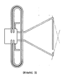
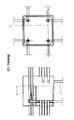
- the position of the Dipoles assure that these elements will receive transmitted signals, incoming trough the elements E-J-K-L- and M are transmitted to a steeringscreen (draw.XGI).
- This screen takes care that the pictures (signals) and waves to be recived are free from reflection and other disturbing elements.
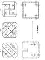
- the signals enter the housing of the elements,where they are connected to 4 element-holders.
- the signals are transmitted to a series of prints that take care for the following transmitting of the signals.
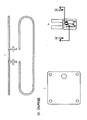
- the prints are connected and linked by means of a Pole connectionfilter with 2 tubetrimmers avoiding an overload of signals on the exitsignal of the aerial. Otherwise an overload could enter the receiver and disturb the picture.
- the prints also can be omitted.
- the parts are placed in the housing without connection, which is possible because after the assembling the housing will be filled with cast resin or epoxyresin resulting in a definite separation of the elements and avoiding internal failures.
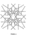
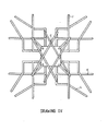
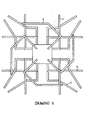
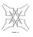
- FIG. 1 show the side-views of the aerial types A-B-C-D and E, while the drawings II-IV-V-VI and VII show the top-views of the different types.
- the elements of above mentioned aerials are made- from a certain kind of Duralmin Alumium, where the bars round 4mm are made from .
- Alumium is chosen because of the different atmos- feric influences. Depending on the circumstances also other materials can be used-some of them are mentioned before.Both thicker and thinner types are useful depending on the demands made and the chosen possibilities.
- the elements L (see draw. XII L) are placed in an element-holder acc. to drawing IX A. Over or under this holder the elements J and K are installed ( draw. XI J and XII K).
- connectionfilter draw. XI H
- print G I draw.X G I
- tow trimmers are placed on print III (draw. X III).
- the elements M are placed (draw. XIII M) on the print II and III (draw. X GII and GIII), after that the trimmers are assembled and connected. After assembling and casting a lid (draw. XI I) is placed and the unit is ready now for the setting and control procedures.
- the aerial After checking the reception of Radiowaves and TV image lines the aerial is ready for installation.
- the aerial can be installed in many ways. It depends on the situation of the object the aerial has to be placed on.
Landscapes
- Aerials With Secondary Devices (AREA)
Priority Applications (1)
| Application Number | Priority Date | Filing Date | Title |
|---|---|---|---|
| EP80201214A EP0054584A1 (de) | 1980-12-19 | 1980-12-19 | Breitbandantennensystem |
Applications Claiming Priority (1)
| Application Number | Priority Date | Filing Date | Title |
|---|---|---|---|
| EP80201214A EP0054584A1 (de) | 1980-12-19 | 1980-12-19 | Breitbandantennensystem |
Publications (1)
| Publication Number | Publication Date |
|---|---|
| EP0054584A1 true EP0054584A1 (de) | 1982-06-30 |
Family
ID=8187060
Family Applications (1)
| Application Number | Title | Priority Date | Filing Date |
|---|---|---|---|
| EP80201214A Withdrawn EP0054584A1 (de) | 1980-12-19 | 1980-12-19 | Breitbandantennensystem |
Country Status (1)
| Country | Link |
|---|---|
| EP (1) | EP0054584A1 (de) |
Citations (5)
| Publication number | Priority date | Publication date | Assignee | Title |
|---|---|---|---|---|
| US2780808A (en) * | 1953-12-15 | 1957-02-05 | Marvin P Middlemark | High frequency antennas |
| GB1024367A (en) * | 1962-10-04 | 1966-03-30 | Siemens Ag | Aerial arrays for electromagnetic-wave radiation |
| US3932874A (en) * | 1974-09-11 | 1976-01-13 | Rca Corporation | Broadband turnstile antenna |
| US4030101A (en) * | 1974-09-06 | 1977-06-14 | Kazuhisa Satoh | Regular eight face polyhedral antenna element |
| US4083051A (en) * | 1976-07-02 | 1978-04-04 | Rca Corporation | Circularly-polarized antenna system using tilted dipoles |
-
1980
- 1980-12-19 EP EP80201214A patent/EP0054584A1/de not_active Withdrawn
Patent Citations (5)
| Publication number | Priority date | Publication date | Assignee | Title |
|---|---|---|---|---|
| US2780808A (en) * | 1953-12-15 | 1957-02-05 | Marvin P Middlemark | High frequency antennas |
| GB1024367A (en) * | 1962-10-04 | 1966-03-30 | Siemens Ag | Aerial arrays for electromagnetic-wave radiation |
| US4030101A (en) * | 1974-09-06 | 1977-06-14 | Kazuhisa Satoh | Regular eight face polyhedral antenna element |
| US3932874A (en) * | 1974-09-11 | 1976-01-13 | Rca Corporation | Broadband turnstile antenna |
| US4083051A (en) * | 1976-07-02 | 1978-04-04 | Rca Corporation | Circularly-polarized antenna system using tilted dipoles |
Similar Documents
| Publication | Publication Date | Title |
|---|---|---|
| US5600333A (en) | Active repeater antenna assembly | |
| US6999032B2 (en) | Antenna system employing floating ground plane | |
| US5568157A (en) | Dual purpose, low profile antenna | |
| ES2108711T3 (es) | Procesador de datos radiofrecuencia para television por cable. | |
| US4907291A (en) | Transmitter/receiver apparatus | |
| US7289062B2 (en) | Method and device for accurately pointing a satellite earth station antenna | |
| SE514956C2 (sv) | Antennenhet för mottagande av elektromagnetiska signaler i ett fordon | |
| US3196438A (en) | Antenna system | |
| US3482250A (en) | Dipole antenna array having equally spaced dipoles of decreasing lengths | |
| EP0054584A1 (de) | Breitbandantennensystem | |
| JPH04291807A (ja) | 通信受信用アレーアンテナ | |
| EP0840268B1 (de) | Navigationsvorrichtung mit Mehrfach-FM-Signalempfangsmöglichkeit | |
| US4608565A (en) | Indoor/outdoor thermometer with remote sensing unit | |
| US6064347A (en) | Dual frequency, low profile antenna for low earth orbit satellite communications | |
| US5414437A (en) | Dual frequency interleaved slot antenna | |
| CN214411526U (zh) | 一种射频识别天线单元及多频段监测天线装置 | |
| JP4302561B2 (ja) | アンテナ装置及びギャップフィラーシステム | |
| US5050236A (en) | Radio frequency field strength enhancer | |
| US2538497A (en) | Antenna connector system | |
| US7072649B2 (en) | Multiple purpose antenna system | |
| US20240213653A1 (en) | Transmission coupler | |
| US2719919A (en) | Built-in antenna system | |
| US4290069A (en) | Directional antenna for long range T.V. signal reception | |
| US20250015487A1 (en) | Vehicle antenna device | |
| JPH0946081A (ja) | 電子機器ケース |
Legal Events
| Date | Code | Title | Description |
|---|---|---|---|
| PUAI | Public reference made under article 153(3) epc to a published international application that has entered the european phase |
Free format text: ORIGINAL CODE: 0009012 |
|
| AK | Designated contracting states |
Designated state(s): AT BE CH DE FR GB IT LI LU NL SE |
|
| 17P | Request for examination filed |
Effective date: 19821230 |
|
| RAP1 | Party data changed (applicant data changed or rights of an application transferred) |
Owner name: VAN MULLEKOM INNOVATION B.V. |
|
| STAA | Information on the status of an ep patent application or granted ep patent |
Free format text: STATUS: THE APPLICATION IS DEEMED TO BE WITHDRAWN |
|
| 18D | Application deemed to be withdrawn |
Effective date: 19850306 |
|
| RIN1 | Information on inventor provided before grant (corrected) |
Inventor name: VAN VEEN, HANS JACOBUS FRITS |