EP0054051B1 - Bicycle storeroom - Google Patents
Bicycle storeroom Download PDFInfo
- Publication number
- EP0054051B1 EP0054051B1 EP19810901818 EP81901818A EP0054051B1 EP 0054051 B1 EP0054051 B1 EP 0054051B1 EP 19810901818 EP19810901818 EP 19810901818 EP 81901818 A EP81901818 A EP 81901818A EP 0054051 B1 EP0054051 B1 EP 0054051B1
- Authority
- EP
- European Patent Office
- Prior art keywords
- door
- bicycle
- storeroom
- fastening device
- hinges
- Prior art date
- Legal status (The legal status is an assumption and is not a legal conclusion. Google has not performed a legal analysis and makes no representation as to the accuracy of the status listed.)
- Expired
Links
Images


Classifications
-
- B—PERFORMING OPERATIONS; TRANSPORTING
- B62—LAND VEHICLES FOR TRAVELLING OTHERWISE THAN ON RAILS
- B62H—CYCLE STANDS; SUPPORTS OR HOLDERS FOR PARKING OR STORING CYCLES; APPLIANCES PREVENTING OR INDICATING UNAUTHORIZED USE OR THEFT OF CYCLES; LOCKS INTEGRAL WITH CYCLES; DEVICES FOR LEARNING TO RIDE CYCLES
- B62H3/00—Separate supports or holders for parking or storing cycles
- B62H3/12—Hanging-up devices
-
- B—PERFORMING OPERATIONS; TRANSPORTING
- B62—LAND VEHICLES FOR TRAVELLING OTHERWISE THAN ON RAILS
- B62H—CYCLE STANDS; SUPPORTS OR HOLDERS FOR PARKING OR STORING CYCLES; APPLIANCES PREVENTING OR INDICATING UNAUTHORIZED USE OR THEFT OF CYCLES; LOCKS INTEGRAL WITH CYCLES; DEVICES FOR LEARNING TO RIDE CYCLES
- B62H3/00—Separate supports or holders for parking or storing cycles
- B62H3/02—Separate supports or holders for parking or storing cycles involving means for gripping the cycle by the handlebars or by the upper part of the frame
Definitions
- the subject of the present invention is a bicycle storeroom, wherein the bicycle is arranged to be stored in the vertical position, i.e. in a position in which the straight line passing via the front and rear axles of the bicycle is substantially vertical, and wherein the door of the storeroom is hinged from above its middle, as viewed in the vertical direction, so as to be opened by tipping it from the vertical position closing the storeroom to the horizontal position so that the door portion placed above the hinges, if any, is pivoted into the storeroom and the portion below the hinges is pivoted outside the storeroom.
- the object of the present invention is to eliminate the above drawbacks, and the invention is characterized in that on the lower face of the plane of a door in the opened position, or at least as functionally connected to the lower face, there is a fastening device at the proximity of the hinges of the door, to which fastening device the bicycle, which has been pushed to underneath the door, is fastened by the handle bar, as well as possibly additionally a second fastening device fitted to the door, for also fastening the bicycle by the saddle, whereby, when the door is closed, the bicycle turns along with the door into the storeroom to the storage position.
- the bicycle storeroom 2 door 1 is hinged above its middle, as viewed in the vertical direction, at both of its sides to the door opening of the storeroom 2.
- the door 1 is opened by tipping, by pivoting it around the hinge section 3, i.e. in practice by pulling the portion of the door 1 placed underneath the hinge section 3 outwards and upwards, whereby the door portion placed above the hinge section is turned into the storeroom 2.
- the door 1 is opened to the horizontal position, the door is locked in that position, whereby it is easy to fasten the bicycle to the door.
- the mechanism by means of which the door 1 can be made to remain in the horizontal position easily and simply may be any arrangement whatsoever suitable for the purpose concerned, for example an arrangement similar to those used in connection with tail gates of cars opening upwards in order to keep the tail gate in the upper position.
- the bicycle fastening devices are placed at the lower face of the door 1.
- the bicycle is pushed to underneath the door 1 in the opened position, it is easy to attach the bicycle to the fastening devices placed on the door 1, e.g. as hanging by the handle bar or as hanging by the handle bar and the saddle.
- the locking that keeps the door 1 in the horizontal position is opened by means of a little jerk, whereupon the door 1 can be closed. Even a child with little strength is strong enough to place the bicycle himself to the fastening devices at the door 1 and to turn the bicycle up to the storage position into the storeroom 2, because in this connection the door 1 functions as a lever arm.
- the door 1 of the storeroom 2 is closed, it is locked, whereby the bicycle is safe from thieves and from mischief makers.
- the bicycle fastening devices on the door 1 are preferably such that, at the same time as the storeroom 2 door is locked, the locking mechanism 4 simultaneously locks the bicycle to its fastening devices.
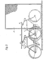
- Figure 3 shows a constructional embodiment differing from that described above, wherein the bicycle is coupled to the door 5 by the handle bar alone.
- the bicycle fastening devices 6 are placed underneath the door 5.
- Figure 4 clarifies the mechanical operation of the fastening devices 6.
- the bicycle is placed underneath the door 5 and the fastening device 6 is, in its position shifted to the bottom end of the door 5, fastened to the handle bar of the bicycle by means of the claw 8 of the fastening arm 7.
- the claw 8 is preferably a fork which grasps the handle bar at both sides of its middle point.
- the fastening arm 7 can be adjusted in accordance with the bicycle height at each particular time concerned, and under these circumstances it is never necessary to lift the bicycle onto the fastening device 6.
- the fastening device 6 glides by means of a rider 10 along a glide arm 11 to the end of the glide arm 11 placed next to the upper end of the door 5.
- the locking 12 of the rider 10 locks the fastening device 6 by means of a pin 14 to the notches 13 on the glide arm 11, and the bicycle is thereby in the storage position.
- the door 5 is opened to the horizontal position, whereby the bicycle is fastened to the fastening device 6 at the top end of the glide arm 11.
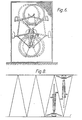
- Figures 10 and 11 show a particularly favourable embodiment of a bicycle fastening device 17 controlled by the door 16 of the bicycle storeroom, which fastening device is by means of an articulated joint at 18 fastened to the upper part of the door opening and whose movement is controlled by the movement of the door 16 by the intermediate of levers 19 and 20.
- the fastening device 17 together with the lever systems 19 and 20 operating it come out more closely from Figure 11.
- the pivot arm 21 of the fastening device 17 is, at its free end, provided with a two-branch hook 22, to which the bicycle is attached at the middle of its handle bar. At its other end the pivot arm 21 is, by means of an articulated joint at 18, fastened to the upper part of the door opening.
- the lever 19 is also fastened to the articulated joint point 18 at one of its ends.
- the lever 20 is fastened by means of an articulated joint to the opposite end of the lever 19, which lever 20 is, on the other hand, at its opposite end, by means of an articulated joint fastened to the door 16.
- a pushing piece 23 projecting from the lever 19 down is fastened rigidly to the lever 19.
- a counter-piece 24, resting against the pushing piece 23, is fastened to the pivot arm 21 of the fastening device 17.
- the pivot arm 21 can pivot freely upwards around its pivot point 18 as lifted by the handle bar of the bicycle until the hook 22 of the pivot arm 21 is at the level of the handle bar and the handle bar of the bicycle then penetrates into the hook 22.
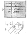
- the bicycle storeroom in accordance with the present invention permits completely safe and convenient storage of three bicycles within an area of about 1.5 square metres, provided that the storeroom is used from both sides, whereby the bicycles are placed as interlocking one another in the way shown in Figures 6 and 7.
- the bicycle is particularly important that, when the door 1 is locked, the bicycle is at the same time locked to its fastening devices, so that the bicycle cannot be taken out from the storeroom from the opposite side, but only through the door through which it was placed into the storeroom.
- Figure 8 shows a favourable embodiment of the arrangement shown in Figures 6 and 7, by making the storerooms as of triangular bottom form, whereby the storerooms can be provided with partition walls.
- Figure 9 shows another favourable embodiment, wherein a set of storerooms has been assembled into circular form out of storerooms of triangular bottom form.
Abstract
Description
- The subject of the present invention is a bicycle storeroom, wherein the bicycle is arranged to be stored in the vertical position, i.e. in a position in which the straight line passing via the front and rear axles of the bicycle is substantially vertical, and wherein the door of the storeroom is hinged from above its middle, as viewed in the vertical direction, so as to be opened by tipping it from the vertical position closing the storeroom to the horizontal position so that the door portion placed above the hinges, if any, is pivoted into the storeroom and the portion below the hinges is pivoted outside the storeroom.
- In prior art, vehicle storage or transportation spaces are known wherein the door is opened as a loading bridge or base onto which the vehicle is driven and along with which the vehicle is turned to vertical position into the storage or transportation space when the door is closed. Constructions of the said type are described, e.g., in the U.S. Patents 3,661,098 and 3,872,983. A storeroom is also previously known in which the bicycle is kept in the vertical position. In the storeroom of this type the bringing of the bicycle to the vertical position, however, requires such abundant and cumbersome auxiliary equipment, as illustrated by German Patent 112,780, that it is not relevant to present-day use.
- Various types of bicycle stands are also known in which the bicycle is hanging or stands vertically or diagonally. Children or women are hardly ever strong enough to lift their bicycle, e.g., onto a hook hanging from the roof. Moreover, in conventional bicycle storage stands - even if the bicycle were locked to the stand - the bicycle is open to mischief makers.
- The object of the present invention is to eliminate the above drawbacks, and the invention is characterized in that on the lower face of the plane of a door in the opened position, or at least as functionally connected to the lower face, there is a fastening device at the proximity of the hinges of the door, to which fastening device the bicycle, which has been pushed to underneath the door, is fastened by the handle bar, as well as possibly additionally a second fastening device fitted to the door, for also fastening the bicycle by the saddle, whereby, when the door is closed, the bicycle turns along with the door into the storeroom to the storage position.
- The invention comes out more closely from the following description and from the attached drawings, wherein
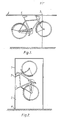
- Figure 1 is a side view of a bicycle storeroom door which has been opened to the horizontal position and to which the bicycle has been hung by the handle bar and the saddle,
- Figure 2 is a side view of a situation in which the bicycle storeroom door has been closed and the bicycle has turned along with the door into the storeroom to the storage position.
- Figure 3 shows a solution type alternative to the embodiment shown in Figure 1, wherein the door is low,
- Figure 4 is a more detailed side view of the construction of the fastening device shown in Figure 3,
- Figure 5 is a detailed view of the locking of the fastening device shown in Figure 4 to the upper position,
- Figures 6 and 7 show an advantageous embodiment of the present invention, wherein the storeroom is designed as two-sided and the bicycles are placed into the storeroom as interlocking each other alternatingly from either side of the storeroom,
- Figures 8 and 9 show advantageous embodiments of the invention as viewed from the top, the storerooms here having narrow triangular base form,
- Figure 10 shows a solution type alternative to the embodiments shown in Figures 1 and 3, as a side view, and
- Figure 11 is a more detailed side view of the construction of the fastening device of Figure 10.
- As shown in Figures 1 and 2, the
bicycle storeroom 2 door 1 is hinged above its middle, as viewed in the vertical direction, at both of its sides to the door opening of thestoreroom 2. The door 1 is opened by tipping, by pivoting it around the hinge section 3, i.e. in practice by pulling the portion of the door 1 placed underneath the hinge section 3 outwards and upwards, whereby the door portion placed above the hinge section is turned into thestoreroom 2. When the door 1 is opened to the horizontal position, the door is locked in that position, whereby it is easy to fasten the bicycle to the door. The mechanism by means of which the door 1 can be made to remain in the horizontal position easily and simply may be any arrangement whatsoever suitable for the purpose concerned, for example an arrangement similar to those used in connection with tail gates of cars opening upwards in order to keep the tail gate in the upper position. After the door 1 has been opened to the horizontal position, the bicycle fastening devices are placed at the lower face of the door 1. When the bicycle is pushed to underneath the door 1 in the opened position, it is easy to attach the bicycle to the fastening devices placed on the door 1, e.g. as hanging by the handle bar or as hanging by the handle bar and the saddle. When the bicycle is in position at the fastening devices on the door 1 and thestoreroom 2 is to be closed, the locking that keeps the door 1 in the horizontal position is opened by means of a little jerk, whereupon the door 1 can be closed. Even a child with little strength is strong enough to place the bicycle himself to the fastening devices at the door 1 and to turn the bicycle up to the storage position into thestoreroom 2, because in this connection the door 1 functions as a lever arm. When the door 1 of thestoreroom 2 is closed, it is locked, whereby the bicycle is safe from thieves and from mischief makers. The bicycle fastening devices on the door 1 are preferably such that, at the same time as thestoreroom 2 door is locked, the locking mechanism 4 simultaneously locks the bicycle to its fastening devices. - Figure 3 shows a constructional embodiment differing from that described above, wherein the bicycle is coupled to the door 5 by the handle bar alone. When the door 5 has been opened to the horizontal position, the bicycle fastening devices 6 are placed underneath the door 5. Figure 4 clarifies the mechanical operation of the fastening devices 6. After the door 5 has been opened to the horizontal position, the bicycle is placed underneath the door 5 and the fastening device 6 is, in its position shifted to the bottom end of the door 5, fastened to the handle bar of the bicycle by means of the claw 8 of the fastening arm 7. The claw 8 is preferably a fork which grasps the handle bar at both sides of its middle point. Owing to the adjusting
arm 9, the fastening arm 7 can be adjusted in accordance with the bicycle height at each particular time concerned, and under these circumstances it is never necessary to lift the bicycle onto the fastening device 6. From the said position, when the bicycle is pushed, the fastening device 6 glides by means of arider 10 along a glide arm 11 to the end of the glide arm 11 placed next to the upper end of the door 5. When the door 5 is closed, thelocking 12 of therider 10 locks the fastening device 6 by means of apin 14 to thenotches 13 on the glide arm 11, and the bicycle is thereby in the storage position. When one wishes to take the bicycle out of thestoreroom 15, the door 5 is opened to the horizontal position, whereby the bicycle is fastened to the fastening device 6 at the top end of the glide arm 11. - Next, the bicycle is pulled out, whereby the fastening device 6 moves along with the bicycle to the lower end of the glide arm 11, and finally the fastening arm 7 is detached from the handle bar of the bicycle.
- Figures 10 and 11 show a particularly favourable embodiment of a
bicycle fastening device 17 controlled by thedoor 16 of the bicycle storeroom, which fastening device is by means of an articulated joint at 18 fastened to the upper part of the door opening and whose movement is controlled by the movement of thedoor 16 by the intermediate oflevers fastening device 17 together with thelever systems pivot arm 21 of thefastening device 17 is, at its free end, provided with a two-branch hook 22, to which the bicycle is attached at the middle of its handle bar. At its other end thepivot arm 21 is, by means of an articulated joint at 18, fastened to the upper part of the door opening. Thelever 19 is also fastened to the articulatedjoint point 18 at one of its ends. Thelever 20 is fastened by means of an articulated joint to the opposite end of thelever 19, whichlever 20 is, on the other hand, at its opposite end, by means of an articulated joint fastened to thedoor 16. As is shown in Fig. 11, a pushingpiece 23 projecting from thelever 19 down is fastened rigidly to thelever 19. Acounter-piece 24, resting against the pushingpiece 23, is fastened to thepivot arm 21 of thefastening device 17. - When the bicycle is pushed in the direction of the
arrow 25 towards thepivot arm 21 of thefastening device 17, thepivot arm 21 can pivot freely upwards around itspivot point 18 as lifted by the handle bar of the bicycle until thehook 22 of thepivot arm 21 is at the level of the handle bar and the handle bar of the bicycle then penetrates into thehook 22. When thedoor 16, whose locking arrangement that keeps it in the horizontal position is not described separately in this connection, starts being turned downwards in the direction of thearrow 26, thedoor 16, by the intermediate of thelever arms piece 23 against thecounter-piece 24 of thepivot arm 21, and when the door is turned further towards its closed position, it forces thepivot arm 21, by the intermediate of thelever arms piece 23 and thecounter-piece 24, to pivot around itslinkage point 18 upwards up to the position shown by broken lines in Figure 10. On the other hand, thepivot arm 21 lifts the bicycle along with it into the storeroom to the storage position, as is shown by broken lines in Figure 10. - The bicycle storeroom in accordance with the present invention permits completely safe and convenient storage of three bicycles within an area of about 1.5 square metres, provided that the storeroom is used from both sides, whereby the bicycles are placed as interlocking one another in the way shown in Figures 6 and 7. In this connection it is particularly important that, when the door 1 is locked, the bicycle is at the same time locked to its fastening devices, so that the bicycle cannot be taken out from the storeroom from the opposite side, but only through the door through which it was placed into the storeroom.
- Figure 8 shows a favourable embodiment of the arrangement shown in Figures 6 and 7, by making the storerooms as of triangular bottom form, whereby the storerooms can be provided with partition walls.
- Figure 9 shows another favourable embodiment, wherein a set of storerooms has been assembled into circular form out of storerooms of triangular bottom form.
Claims (2)
Priority Applications (1)
| Application Number | Priority Date | Filing Date | Title |
|---|---|---|---|
| AT81901818T ATE9453T1 (en) | 1980-06-24 | 1981-06-17 | FAR WHEEL WAREHOUSE. |
Applications Claiming Priority (2)
| Application Number | Priority Date | Filing Date | Title |
|---|---|---|---|
| FI802014 | 1980-06-24 | ||
| FI802014A FI62646C (en) | 1980-06-24 | 1980-06-24 | FOERVARINGSSKAOP FOER CYKEL |
Publications (2)
| Publication Number | Publication Date |
|---|---|
| EP0054051A1 EP0054051A1 (en) | 1982-06-23 |
| EP0054051B1 true EP0054051B1 (en) | 1984-09-19 |
Family
ID=8513589
Family Applications (1)
| Application Number | Title | Priority Date | Filing Date |
|---|---|---|---|
| EP19810901818 Expired EP0054051B1 (en) | 1980-06-24 | 1981-06-17 | Bicycle storeroom |
Country Status (4)
| Country | Link |
|---|---|
| EP (1) | EP0054051B1 (en) |
| DK (1) | DK156633C (en) |
| FI (1) | FI62646C (en) |
| WO (1) | WO1982000023A1 (en) |
Families Citing this family (6)
| Publication number | Priority date | Publication date | Assignee | Title |
|---|---|---|---|---|
| FI76298C (en) * | 1984-02-08 | 1988-10-10 | Aarno Arvid Laukkonen | Lockers for bicycles and sporting goods |
| FR2559445B1 (en) * | 1984-02-09 | 1987-02-13 | Ind Dessin Etude Services | DEVICE FOR HOLDING CYCLES IN A VERTICAL POSITION |
| DK164812C (en) * | 1988-03-16 | 1993-01-11 | Keld Andersen | CYCLE CONTAINS FOR STORAGE OF MULTIPLE CYCLES |
| DE9005940U1 (en) * | 1990-05-25 | 1990-09-27 | Hildenbrand, Christian, 6822 Altlussheim, De | |
| EP2732111A1 (en) * | 2011-07-11 | 2014-05-21 | Advanced Locker Systems, LLC | Storage device |
| WO2018191687A1 (en) | 2017-04-14 | 2018-10-18 | Dropbikes Llc | Bicycle storage assembly |
Family Cites Families (4)
| Publication number | Priority date | Publication date | Assignee | Title |
|---|---|---|---|---|
| DE112780C (en) * | ||||
| DE1020886B (en) * | 1955-04-12 | 1957-12-12 | Ubbo Wilhelm Groenendal | Bicycle parking device |
| DE1097303B (en) * | 1957-12-10 | 1961-01-12 | August Schmidt | Holding device for bicycles, mopeds and motorcycles |
| US3770133A (en) * | 1972-02-11 | 1973-11-06 | Miller E | Bicycle storage device |
-
1980
- 1980-06-24 FI FI802014A patent/FI62646C/en not_active IP Right Cessation
-
1981
- 1981-06-17 WO PCT/FI1981/000048 patent/WO1982000023A1/en active IP Right Grant
- 1981-06-17 EP EP19810901818 patent/EP0054051B1/en not_active Expired
-
1982
- 1982-02-15 DK DK064582A patent/DK156633C/en not_active IP Right Cessation
Also Published As
| Publication number | Publication date |
|---|---|
| EP0054051A1 (en) | 1982-06-23 |
| FI62646C (en) | 1983-02-10 |
| DK156633C (en) | 1990-02-05 |
| DK64582A (en) | 1982-02-15 |
| WO1982000023A1 (en) | 1982-01-07 |
| FI802014A (en) | 1981-12-25 |
| DK156633B (en) | 1989-09-18 |
| FI62646B (en) | 1982-10-29 |
Similar Documents
| Publication | Publication Date | Title |
|---|---|---|
| US5121959A (en) | Slide mount for pick-up truck toolboxes | |
| EP0054051B1 (en) | Bicycle storeroom | |
| US4005648A (en) | Trash compactor | |
| JPH04504741A (en) | Window with main frame and two openable window frames mounted on a pitched roof | |
| US2234040A (en) | Convertible body | |
| US5052200A (en) | Locking device for lock components in/on vehicles | |
| EP0218513A1 (en) | Vertically and laterally movable fire-door, mounted on slides, with an automatic lock | |
| US3331552A (en) | Mailbox with automatic signal | |
| US2070046A (en) | Door prop | |
| SE518443C2 (en) | Device for load support | |
| US3034825A (en) | Container chassis combination | |
| US2975490A (en) | Laterally movable doors for railway cars | |
| CN108974583B (en) | A kind of glass inder pot of high-effective and labour-saving | |
| CN212861694U (en) | Mother trolley | |
| CN214058735U (en) | Bury bucket with theftproof structure | |
| GB1599562A (en) | Pivotal containers | |
| JP3848729B2 (en) | Opening / closing lid locking device | |
| JPH0111912Y2 (en) | ||
| IT202000022288A1 (en) | SAFETY DEVICE FOR THE RETENTION OF GARBAGE COLLECTION BIN | |
| KR20010098424A (en) | Sluice Lifter | |
| JPS5912398Y2 (en) | Fall prevention device for telescoping gates | |
| JPS6139640Y2 (en) | ||
| CH305988A (en) | Motorcycle boxes with door. | |
| JPS6015459Y2 (en) | Multi-stage drawer cabinet | |
| JPS5919674Y2 (en) | Lampway for door |
Legal Events
| Date | Code | Title | Description |
|---|---|---|---|
| PUAI | Public reference made under article 153(3) epc to a published international application that has entered the european phase |
Free format text: ORIGINAL CODE: 0009012 |
|
| 17P | Request for examination filed |
Effective date: 19820210 |
|
| AK | Designated contracting states |
Designated state(s): AT DE FR GB NL SE |
|
| GRAA | (expected) grant |
Free format text: ORIGINAL CODE: 0009210 |
|
| AK | Designated contracting states |
Designated state(s): AT DE FR GB NL SE |
|
| PG25 | Lapsed in a contracting state [announced via postgrant information from national office to epo] |
Ref country code: AT Effective date: 19840919 |
|
| REF | Corresponds to: |
Ref document number: 9453 Country of ref document: AT Date of ref document: 19841015 Kind code of ref document: T |
|
| REF | Corresponds to: |
Ref document number: 3166163 Country of ref document: DE Date of ref document: 19841025 |
|
| ET | Fr: translation filed | ||
| PLBE | No opposition filed within time limit |
Free format text: ORIGINAL CODE: 0009261 |
|
| STAA | Information on the status of an ep patent application or granted ep patent |
Free format text: STATUS: NO OPPOSITION FILED WITHIN TIME LIMIT |
|
| 26N | No opposition filed | ||
| PGFP | Annual fee paid to national office [announced via postgrant information from national office to epo] |
Ref country code: FR Payment date: 19920612 Year of fee payment: 12 |
|
| PGFP | Annual fee paid to national office [announced via postgrant information from national office to epo] |
Ref country code: SE Payment date: 19920617 Year of fee payment: 12 |
|
| PGFP | Annual fee paid to national office [announced via postgrant information from national office to epo] |
Ref country code: NL Payment date: 19920630 Year of fee payment: 12 |
|
| PGFP | Annual fee paid to national office [announced via postgrant information from national office to epo] |
Ref country code: DE Payment date: 19920821 Year of fee payment: 12 |
|
| PGFP | Annual fee paid to national office [announced via postgrant information from national office to epo] |
Ref country code: GB Payment date: 19921102 Year of fee payment: 12 |
|
| PG25 | Lapsed in a contracting state [announced via postgrant information from national office to epo] |
Ref country code: GB Effective date: 19930617 |
|
| PG25 | Lapsed in a contracting state [announced via postgrant information from national office to epo] |
Ref country code: SE Effective date: 19930618 |
|
| PG25 | Lapsed in a contracting state [announced via postgrant information from national office to epo] |
Ref country code: NL Effective date: 19940101 |
|
| GBPC | Gb: european patent ceased through non-payment of renewal fee |
Effective date: 19930617 |
|
| PG25 | Lapsed in a contracting state [announced via postgrant information from national office to epo] |
Ref country code: FR Effective date: 19940228 |
|
| PG25 | Lapsed in a contracting state [announced via postgrant information from national office to epo] |
Ref country code: DE Effective date: 19940301 |
|
| REG | Reference to a national code |
Ref country code: FR Ref legal event code: ST |
|
| EUG | Se: european patent has lapsed |
Ref document number: 81901818.5 Effective date: 19940110 |