EP0053984A2 - Method and apparatus for the automatic control of the integrity of assembling welds - Google Patents
Method and apparatus for the automatic control of the integrity of assembling welds Download PDFInfo
- Publication number
- EP0053984A2 EP0053984A2 EP81401954A EP81401954A EP0053984A2 EP 0053984 A2 EP0053984 A2 EP 0053984A2 EP 81401954 A EP81401954 A EP 81401954A EP 81401954 A EP81401954 A EP 81401954A EP 0053984 A2 EP0053984 A2 EP 0053984A2
- Authority
- EP
- European Patent Office
- Prior art keywords
- inspection head
- axis
- carriage
- rotation
- weld
- Prior art date
- Legal status (The legal status is an assumption and is not a legal conclusion. Google has not performed a legal analysis and makes no representation as to the accuracy of the status listed.)
- Ceased
Links
Images

Classifications
-
- G—PHYSICS
- G01—MEASURING; TESTING
- G01N—INVESTIGATING OR ANALYSING MATERIALS BY DETERMINING THEIR CHEMICAL OR PHYSICAL PROPERTIES
- G01N29/00—Investigating or analysing materials by the use of ultrasonic, sonic or infrasonic waves; Visualisation of the interior of objects by transmitting ultrasonic or sonic waves through the object
- G01N29/22—Details, e.g. general constructional or apparatus details
- G01N29/26—Arrangements for orientation or scanning by relative movement of the head and the sensor
- G01N29/265—Arrangements for orientation or scanning by relative movement of the head and the sensor by moving the sensor relative to a stationary material
-
- F—MECHANICAL ENGINEERING; LIGHTING; HEATING; WEAPONS; BLASTING
- F16—ENGINEERING ELEMENTS AND UNITS; GENERAL MEASURES FOR PRODUCING AND MAINTAINING EFFECTIVE FUNCTIONING OF MACHINES OR INSTALLATIONS; THERMAL INSULATION IN GENERAL
- F16L—PIPES; JOINTS OR FITTINGS FOR PIPES; SUPPORTS FOR PIPES, CABLES OR PROTECTIVE TUBING; MEANS FOR THERMAL INSULATION IN GENERAL
- F16L55/00—Devices or appurtenances for use in, or in connection with, pipes or pipe systems
- F16L55/26—Pigs or moles, i.e. devices movable in a pipe or conduit with or without self-contained propulsion means
-
- G—PHYSICS
- G21—NUCLEAR PHYSICS; NUCLEAR ENGINEERING
- G21C—NUCLEAR REACTORS
- G21C17/00—Monitoring; Testing ; Maintaining
- G21C17/003—Remote inspection of vessels, e.g. pressure vessels
- G21C17/013—Inspection vehicles
-
- F—MECHANICAL ENGINEERING; LIGHTING; HEATING; WEAPONS; BLASTING
- F16—ENGINEERING ELEMENTS AND UNITS; GENERAL MEASURES FOR PRODUCING AND MAINTAINING EFFECTIVE FUNCTIONING OF MACHINES OR INSTALLATIONS; THERMAL INSULATION IN GENERAL
- F16L—PIPES; JOINTS OR FITTINGS FOR PIPES; SUPPORTS FOR PIPES, CABLES OR PROTECTIVE TUBING; MEANS FOR THERMAL INSULATION IN GENERAL
- F16L2101/00—Uses or applications of pigs or moles
- F16L2101/30—Inspecting, measuring or testing
-
- F—MECHANICAL ENGINEERING; LIGHTING; HEATING; WEAPONS; BLASTING
- F16—ENGINEERING ELEMENTS AND UNITS; GENERAL MEASURES FOR PRODUCING AND MAINTAINING EFFECTIVE FUNCTIONING OF MACHINES OR INSTALLATIONS; THERMAL INSULATION IN GENERAL
- F16L—PIPES; JOINTS OR FITTINGS FOR PIPES; SUPPORTS FOR PIPES, CABLES OR PROTECTIVE TUBING; MEANS FOR THERMAL INSULATION IN GENERAL
- F16L2101/00—Uses or applications of pigs or moles
- F16L2101/70—Drill-well operations
-
- G—PHYSICS
- G01—MEASURING; TESTING
- G01N—INVESTIGATING OR ANALYSING MATERIALS BY DETERMINING THEIR CHEMICAL OR PHYSICAL PROPERTIES
- G01N2291/00—Indexing codes associated with group G01N29/00
- G01N2291/26—Scanned objects
- G01N2291/267—Welds
-
- Y—GENERAL TAGGING OF NEW TECHNOLOGICAL DEVELOPMENTS; GENERAL TAGGING OF CROSS-SECTIONAL TECHNOLOGIES SPANNING OVER SEVERAL SECTIONS OF THE IPC; TECHNICAL SUBJECTS COVERED BY FORMER USPC CROSS-REFERENCE ART COLLECTIONS [XRACs] AND DIGESTS
- Y02—TECHNOLOGIES OR APPLICATIONS FOR MITIGATION OR ADAPTATION AGAINST CLIMATE CHANGE
- Y02E—REDUCTION OF GREENHOUSE GAS [GHG] EMISSIONS, RELATED TO ENERGY GENERATION, TRANSMISSION OR DISTRIBUTION
- Y02E30/00—Energy generation of nuclear origin
- Y02E30/30—Nuclear fission reactors
Definitions
- the present invention relates to a method and an automatic control device intended to detect, measure, monitor possible cracks and other damage in mechanically welded assemblies. It relates to a vehicle traveling inside a hollow body, carrying a robot arm used to position the measurement probes in contact with the areas to be checked.
- the present invention makes it possible to measure the parameters defining a defect: location, orientation, dimensions. Its implementation is compatible with taking into memory all the corresponding values; moreover, being automatic, it overcomes the uncertainties that accompany any manual process.
- tubular assemblies It is particularly intended for the inspection of welds of tubular assemblies where one of the elements is accessible from the inside. It responds to difficult environmental conditions, it makes it possible to operate in a confined space or a hostile environment such as in nuclear power plants or off-shore. It is suitable for the control of tubular assemblies whether piping, piping, or even tubular lattice, with their connecting nodes between the main frames (drums or piers, chords) and secondary members (bracings ).
- welds In the case of off-shore platforms, for example, which reach colossal dimensions, the welds number in the hundreds.
- the trellis nodes have up to 6 or 8 bracings, with or without stiffening gussets. These welds coincide with particularly stressed areas, susceptible by their complex nature to be subject to manufacturing defects, and by their situation to be subjected to alternating stresses generating fatigue cracks.
- the mechanical device which is the subject of the invention makes it possible to carry out direct, exhaustive, precise and reproducible, rapid measurements which do not require the intervention of an operator. It therefore meets the requirements of in-service inspection.
- it makes it possible to firmly position and correctly orient measuring probes to within a few millimeters in relation to the weld beads and to explore the entire weld bead under these conditions (scanning of the weld by the probes) .
- These probes emit signals and they receive echoes or "images" which indicate the presence of faults.
- the probe scanning area is shown in Figure 1a. Cracks are detected by straight probes and angle ultrasonic probes. The width of the weld corresponds to the area of disappearance of echoes of waves from right feelers, on the outer surface; therefore irregularities in the records will reveal the lack of penetration into the weld root (defect "D” in figure 1). The other cracks, bondings and inclusions (A, B, C, E, F, G fig.1) are detected in the transmitter-receiver mode ("pulse-echo"). We see in these figures 1 that there is no difficulty in detecting cracks on the main member, and that, provided that the welds are fully penetrated, all the cracks in the weld and in the secondary member will also be detected. .
- the control device which moves inside a member allows the control of the welds of the secondary members when these welds are fully penetrated.
- Its function is to move a probe against or near the interior surface of the member, to recognize the location of the welds, and to explore them to find any cracks, by scanning this weld with probes. correctly oriented in relation to the direction of the weld.
- this "internal scanner” (ICS) is lowered into a vertical member 1 on which secondary members 2 have been attached by full penetration welds 3. These welds are controlled by an assembly of ultrasonic probes 44 constituting the measurement probe 43. When the probe controls the diametrically opposite position of the weld, in 4, this probe came in 80 and it turned 180 degrees on itself.
- the SCI (internal scanner") is supported by cables 8 linked to a crankcase 7. These cables provide mechanical support, electrical power to the motors, instrumentation and a demineralized water circuit ensuring the coupling of the probe. Yes the frames were horizontal, a self-propelled cart would be integrated into the SCI.
- the minimum diameter is represented by the member 5 to which correspond the positions 13 and 14 of the jack 12 and of the arm 11 respectively.
- the wheels 15 are locked by braking via the cables 16 which, by the return pulleys 18, are controlled by the motor 17.
- the sci has a fixed part 6 relative to the cables, a mobile part in a squirrel cage rotating around the axis of the SCI, and a fixed lower part also.
- the module 40 carrying the probe moves.
- the telescopic probe holder 41, 42 has come out to bear against the internal surface, it is capable of being oriented by a rotation about its axis.
- the upper fixed part includes a crown 9 as does the lower fixed part '26. On this crown are placed bearings and thrust ball bearings 10 positioning the mobile part. Through the upper fixed part, the electric power cables and the power cables connected to the probe pass. These cables come on a sliding, multi-pole electrical collector, having a fixed part 24 and a rotary part 22, the latter being integral with the rotation of the mobile part.
- the electric cables 23 supply the stepping electric motor 34 which ensures the displacement of the module 40.
- On the upper fixed part is fixed the stepping motor 19 which, by the axis 20 and the pinion 21 ensures the rotation of the movable part 31.
- the fixed crown 9 is also provided with a demineralized water supply arriving via the conduit 81 and opening into a cylindrical groove 82. This water circuit serves to supply the mobile part by a pipe 84 opening into the chamber delimited between the fixed part and the mobile part by the O-rings 83.
- the lower fixed part 26 comprises a stepping motor 89 coupled with the motor 19.
- the collector 29 provides the electrical connection with the lower rotary part 92.
- An electro-hydraulic unit 28 supplied by 30 actuates the jacks of the arms 27. This unit is protected by a cover 88.
- the rotary movable part comprises an upper cylindrical flange and a lower cylindrical flange, connected by tie rods 33 and by a ball screw 32.
- the electrical supply of the lower fixed part is carried out by cables passing through 33.
- the circuit of demineralized water84 is connected to a drum reel 86 carried by the arm 87. From this drum leaves the conduit 93 ensuring the supply of water to the module 40.
- a drum reel 35 keeps the supply cables 36 in tension electrical and instrumentation connected to module 40.
- the module 40 moves on the tie rods 33. It is driven by the ball screw 32, held by the bearings 37, and the rotation of which is controlled by the stepping motor 34 attacking the ring gear 38.
- the module 40 has the function of ensuring the support of the sensors (of the probe) against the member and of orienting this probe relative to the weld.
- the instrumentation cables are connected to the probes which, moreover, will be submerged by a circulation of demineralized water or any other coupling fluid.
- the module comprises a cylindrical well 94, radial.
- This well contains a jacket 45 centered by the bearings 50 and 51, and whose rotation relative to 40 is controlled by a stepping motor. 48 attacking by a bevel gear 49 a toothed crown 71 secured to 45.
- the end of 45 comprises an annular electrical collector, one face 53 of which is integral with 45 while the other face 52 is integral with the module.
- the collector is connected by the cable 75 to the connection socket 46 which receives the end of the cable 36.
- a sealing ring 90 protects the chamber between 94 and 45.
- a water pipe 74 integral with 40 coaxially crosses the face of the jacket 45. It is centered by a bearing 73 and it has an O-ring seal 72.
- the seal is ensured by the gasket 76.
- the telescopic arm has an inner tube 42 and a coaxial tube 41. They slide without turning inside 45 thanks to the dishes 58, and they are therefore controlled by the rotation of 45.
- the tube 41 includes self-lubricating guide bearings 66 and 68; the tube 42 includes self-lubricating guide bearings 62 and 65.
- the stroke of the inner tube is defined by the length of the seat-63 to the stop 64.
- the stroke of the outer tube 41 is limited to the stop 67 of the jacket .
- the deployment of the telescopic tube is controlled by the rotation of the threaded axis 60 on which slides a nut 61 with ball return secured to the inner tube 42.
- This axis is held concentric by a bearing 59 resting on the jacket and by a plastic ring 100 at the other end.
- the head of 42 carries the probe 43 fitted with ultrasonic feelers 44, individually mounted on springs, so as to compensate for the curvature of the frame and thus to ensure correct coupling.
- the operation of the ICS is as follows: the ICS is lowered to about ten centimeters near a marked position and it is locked in position. The module is then quickly moved once the probe has been removed and has come into contact with the inner surface of the tube. The probe records the passage of the weld because it no longer receives return echoes from the outside surface of the member. It therefore intercepts in its path two signals corresponding to the crossover of the weld by the same generator.
- the module is then positioned halfway between these signals and then it is rotated.
- the new signals in this direction-transverse to the first, define the axis of the secondary member.
- we know the center of this weld we then know its position on the frame with satisfactory precision.
- the stepper motors are then controlled so that the probe completely scans the weld and remains constantly oriented perpendicular to the tangent to the weld: in fact the ultrasonic transducers emit transverse waves (inclined to the normal to the surface) which must be correctly oriented to detect cracks along the weld bead.
- the probe also scans the weld transversely, gradually moving along it.
- the location of the weld is carried out by means of two displacements of the module carrying the inspection head, longitudinally in the axis of the member and circularly by rotation around this axis, and using the probes there. straight with an ultra sonic beam radial.
- the same two movements are used to scan the weld area and simultaneously the inspection head is rotated around its axis in order to always present the probes angle in the right direction. It is indeed in this operation, the angle probes emitting a beam oriented at 45 degrees from the explored surface, that they are used.
- the synchronization of the rotation of the writing head with the scanning is ensured by the means of automatic control by digital computer.
Landscapes
- Engineering & Computer Science (AREA)
- Physics & Mathematics (AREA)
- General Engineering & Computer Science (AREA)
- Chemical & Material Sciences (AREA)
- Analytical Chemistry (AREA)
- General Physics & Mathematics (AREA)
- Life Sciences & Earth Sciences (AREA)
- High Energy & Nuclear Physics (AREA)
- Plasma & Fusion (AREA)
- Biochemistry (AREA)
- General Health & Medical Sciences (AREA)
- Health & Medical Sciences (AREA)
- Immunology (AREA)
- Pathology (AREA)
- Combustion & Propulsion (AREA)
- Mechanical Engineering (AREA)
- Investigating Or Analyzing Materials By The Use Of Ultrasonic Waves (AREA)
- Monitoring And Testing Of Nuclear Reactors (AREA)
Abstract
Dispositif de contrôle automatique des soudures entre pièces tubulaires, utilisable pour le contrôle par ultrasons des soudures des noeuds des plateformes offshore et le contrôle des soudures des circuits nucléaires. Un chariot comporte deux extrémités fixes (6 et 26), avec leurs roues de centrage (15), un équipage mobile avec deux flasques (31 et 92) et des rails de guidage (32, 33); cet équipage tourne sur des roulements (10). Le chariot comporte un-tambour (40) se déplaçant sur les rails et portant un bras téléscopique (42) orientable par rotation sur son axe. L'extrémité du bras porte une tête d'inspection (43). Une commande numérique assure la programmation du déplacement et de l'orientation de la tête d'inspection en regard de la soudure.Device for automatic control of the welds between tubular parts, usable for the ultrasonic control of the welds of the nodes of offshore platforms and the control of the welds of the nuclear circuits. A carriage has two fixed ends (6 and 26), with their centering wheels (15), a mobile assembly with two flanges (31 and 92) and guide rails (32, 33); this crew turns on bearings (10). The carriage comprises a drum (40) moving on the rails and carrying a telescopic arm (42) orientable by rotation on its axis. The end of the arm carries an inspection head (43). A digital control program the movement and orientation of the inspection head facing the weld.
Description
La présente invention a pour objet une méthode et un dispositif de contrôle automatique destinés à détecter, à mesurer,à surveiller des fissures éventuelles et autres dommages dans des assemblages mécano-soudés. Elle concerne un véhicule circulant à l'intérieur d'un corps creux, portant un bras robot servant à positionner les sondes de mesure au contact des zones à contrôler.The present invention relates to a method and an automatic control device intended to detect, measure, monitor possible cracks and other damage in mechanically welded assemblies. It relates to a vehicle traveling inside a hollow body, carrying a robot arm used to position the measurement probes in contact with the areas to be checked.
Qu'il s'agisse de répondre aux exigences de qualité de la fabrication (contrôle initial) ou à celles de l'exploitation (dommages éventuels, corrosion, fatigue...), il est dans bien des cas exigé et nécessaire d'être assuré de l'intégrité d'une structure et de prévenir d'un risque d'accident. Ces diagnostics sont déjà imposés sur les centrales nucléaires, par exemple, et elles le seront prochainement de façon plus critique sur les plate-formes off-shore.Whether it is to meet the quality requirements of manufacturing (initial control) or those of operation (possible damage, corrosion, fatigue ...), it is in many cases required and necessary to be assured of the integrity of a structure and of preventing an accident risk. These diagnoses are already imposed on nuclear power plants, for example, and they will soon be more critical on off-shore platforms.
Actuellement et même pour les exemples précités, dans bien des cas le contrôle est effectué manuellement, ce qui limite considérablement la confiance que l'on peut attendre de ces mesures (off-shore), ou ce qui demande un temps appréciable et implique l'absorption de rayonnement pour les opérateurs (centrales nucléaires).Currently and even for the aforementioned examples, in many cases the control is carried out manually, which considerably limits the confidence that one can expect from these measurements (off-shore), or which requires appreciable time and involves radiation absorption for operators (nuclear power plants).
La présente invention au contraire, permet de mesurer les paramètres définissant un défaut : localisation, orientation, dimensions. Sa mise en oeuvre est compatible avec une prise en mémoire de toutes les valeurs correspondantes ; par ailleurs, étant automatique, elle s'affranchit des incertitudes qui accompagnent tout procédé manuel.The present invention, on the contrary, makes it possible to measure the parameters defining a defect: location, orientation, dimensions. Its implementation is compatible with taking into memory all the corresponding values; moreover, being automatic, it overcomes the uncertainties that accompany any manual process.
Elle est particulièrement destinée à l'inspection des soudures d'assemblages tubulaires où l'un des éléments est accessible de l'intérieur. Elle répond à des conditions difficiles d'environnement, elle permet d'opérer dans un espace confiné ou un environnement hostile tel que dans les centrales nucléaires ou en off-shore. Elle convient au contrôle d'assemblages tubulaires qu'il s'agisse de rabouttage de canalisations, de piquages, ou encore de trellis tubulaires, avec leurs noeuds de raccordement entre les membrures principales (fûts ou piles, chords) et les membrures secondaires (bracings).It is particularly intended for the inspection of welds of tubular assemblies where one of the elements is accessible from the inside. It responds to difficult environmental conditions, it makes it possible to operate in a confined space or a hostile environment such as in nuclear power plants or off-shore. It is suitable for the control of tubular assemblies whether piping, piping, or even tubular lattice, with their connecting nodes between the main frames (drums or piers, chords) and secondary members (bracings ).
Dans le cas de plate-forme off-shore par exemple, qui atteignent des dimensions colossales, les soudures se comptent par centaines. Les noeuds des treillis comportent jusqu'à 6 ou 8 bracings, avec ou sans goussets raidisseurs. Ces soudures coincident avec des zones particulièrement sollicitées, susceptibles par leur nature complexe d'être sujettes à des défauts de fabrication, et par leur situation d'être soumises à des contraintes alternées génératrices de fissures de fatigue.In the case of off-shore platforms, for example, which reach colossal dimensions, the welds number in the hundreds. The trellis nodes have up to 6 or 8 bracings, with or without stiffening gussets. These welds coincide with particularly stressed areas, susceptible by their complex nature to be subject to manufacturing defects, and by their situation to be subjected to alternating stresses generating fatigue cracks.
Le dispositif mécanique objet de l'invention permet de réaliser des mesures directes, exhaustives, précises et reproductibles, rapides et qui ne requièrent pas l'intervention en place d'un opérateur. Il répond donc aux exigences d'une surveillance en service ("in-service inspection"). En pratique, il permet de positionner fermement et d'orienter correctement des palpeurs de mesure à quelques millimètres près par rapport aux cordons de soudure et de faire explorer dans ces conditions l'intégralité du cordon de soudure (balayage de la soudure par les palpeurs). Ces palpeurs émettent des signaux et ils recoivent des échos ou des "images" qui traduisent la présence de défauts. De préférence, on utilisera soit des sondes à courants de Foucault (eddy current) soit des sondes à ultrasons, montées sur une tête de mesure qui est déplacée contre la face interne de la membrure, en regard de la soudure.The mechanical device which is the subject of the invention makes it possible to carry out direct, exhaustive, precise and reproducible, rapid measurements which do not require the intervention of an operator. It therefore meets the requirements of in-service inspection. In practice, it makes it possible to firmly position and correctly orient measuring probes to within a few millimeters in relation to the weld beads and to explore the entire weld bead under these conditions (scanning of the weld by the probes) . These probes emit signals and they receive echoes or "images" which indicate the presence of faults. Preferably, use either eddy current probes or ultrasonic probes, mounted on a measuring head which is moved against the internal face of the frame, facing the welding.
L'invention sera maintenant plus complètement décrite en se référant à un mode de réalisation particulier, nullement limitatif, illustré à l'aide des figures ci-annexées dans lesquelles :
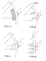
- Les figures 1a, 1b, 1c, 1d, montrent la zone couverte par un balayage des capteurs d'un dispositif de contrôle selon l'invention dans une vue schématique en coupe transversale.
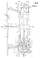
- La figure 2 représente, en coupe longitudinale partielle, le dispositif de contrôle en position dans l'axe d'une membrure principale tubulaire.
- La figure 3 représente,une vue schématique partielle en coupe, selon I-I' de la figure 2.
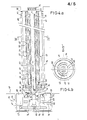
- La figure 4a illustre plus particulièrement la réalisation du module à bras téléscopique que comporte le dispositif de l'invention, dans une vue en coupe selon III-III' de la figure 2.
- La figure 4b représente, une coupe transversale du bras de ce module selon IV-IV' de la figure 4a.
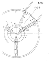
- La figure 5 représente, comme la figure 3, mais avec plus de détails, le dispositif selon l'invention dans une coupe partielle transversalementà une membrure principale dans laquelle il est placé.
- Figures 1a, 1b, 1c, 1d show the area covered by a scanning of the sensors of a control device according to the invention in a schematic view in cross section.
- Figure 2 shows, in partial longitudinal section, the control device in position in the axis of a main tubular member.
- FIG. 3 represents a partial schematic view in section, along II 'of FIG. 2.
- FIG. 4a more particularly illustrates the embodiment of the telescopic arm module that the device of the invention comprises, in a sectional view along III-III 'of FIG. 2.
- Figure 4b shows a cross section of the arm of this module according to IV-IV 'of Figure 4a.
- Figure 5 shows, like Figure 3, but in more detail, the device according to the invention in a partial section transversely to a main frame in which it is placed.
La zone de balayage des palpeurs est indiquée sur la figure 1a. Les fissures sont détectées par des palpeurs droits et des palpeurs d'angle à ultrasons. La largeur de la soudure correspond à la zone de disparition des échos des ondes des palpeurs droits, sur la surface extérieure ; aussi les irrégularités des enregistrements révè- leront-elles les manques de pénétration en racine de soudage (défaut "D" figure 1). Les autres fissures, collages et inclusions (A, B, C, E, F , G fig.1) sont décelées dans le mode émetteur-récepteur ("pulse-echo"). On voit sur ces figures 1 qu'il n'y a aucune difficulté à déceler les fissures sur la membrure principale, et que, pour autant que les soudures sont entièrement pénétrées, toutes les fissures dans la soudure et dans la membrure secondaire seront ellesaussi détectées.The probe scanning area is shown in Figure 1a. Cracks are detected by straight probes and angle ultrasonic probes. The width of the weld corresponds to the area of disappearance of echoes of waves from right feelers, on the outer surface; therefore irregularities in the records will reveal the lack of penetration into the weld root (defect "D" in figure 1). The other cracks, bondings and inclusions (A, B, C, E, F, G fig.1) are detected in the transmitter-receiver mode ("pulse-echo"). We see in these figures 1 that there is no difficulty in detecting cracks on the main member, and that, provided that the welds are fully penetrated, all the cracks in the weld and in the secondary member will also be detected. .
Le dispositif de contrôle qui se déplace à l'intérieur d'une membrure permet le contrôle des soudures des membrures secondaires lorsque ces soudures sont entièrement pénétrées.The control device which moves inside a member allows the control of the welds of the secondary members when these welds are fully penetrated.
Il a pour fonction de déplacer une sonde contre ou à proximité de la surface intérieure de la membrure, de reconnaître l'emplacement des soudures, et d'en effectuer l'exploration pour trouver les fissures éventuelles, par balayage de cette soudure avec des sondes correctement orientées par rapport à la direction de la soudure.Its function is to move a probe against or near the interior surface of the member, to recognize the location of the welds, and to explore them to find any cracks, by scanning this weld with probes. correctly oriented in relation to the direction of the weld.
Dans l'exemple illustré dans les Figures 2, 3, 4, 5, ce "scanner interne" (SCI) est descendu dans une membrure verticale 1 sur laquelle ont été rapportées des membrures secondaires 2 par des soudures à pleine pénétration 3. Ces soudures sont contrôlées par un assemblage de palpeurs à ultrasons 44 constituant la sonde 43 de mesure. Lorsque la sonde contrôle la position diamétralement opposée de la soudure, en 4, cette sonde est venue en 80 et elle a tourné de 180 degrés sur elle-même.Le SCI ("scanner interne") est supporté par des câbles 8 liés à un manneton 7. Ces câDles assurent le maintien mécanique, l'alimentation électrique des moteurs, l'instrumentation et un circuit d'eau déminéralisée assurant le couplage de la sonde. Si les membrures étaient horizontales, on intégrerait un chariot automoteur au SCI.In the example illustrated in Figures 2, 3, 4, 5, this "internal scanner" (ICS) is lowered into a
Le SCI roule et se centre à l'intérieur de 1 grâce à des bras 11 et 27 pourvus de roues 15 en leur extrémité ; ces bras sont déployés par des vérins 12. Ces bras s'accomodent d'une gamme de diamètres de membrures. Le diamètre minimal est représenté par la membrure 5 à laquelle correspondent les positions 13 et 14 du vérin 12 et du bras 11 respectivement. Lorsque le SCI est en position choisie, définie à une dizaine de centimètres près, les roues 15 sont bloquées par freinage par l'intermédiaire des câbles 16 qui, par les poulies de renvoi 18, sont commandées par le moteur 17.The SCI rolls and centers inside 1 thanks to
Le sci comporte une partie fixe 6 par rapport aux câbles, une partie mobile en cage d'écureuil tournant autour de l'axe du SCI, et une partie inférieure fixe également. Sur la partie rotative se déplace le module 40 portant la sonde 43. Le porte-sonde téléscopique 41, 42 est sorti pour venir en appui contre la surface interne, il est susceptible d'être orienté par une rotation autour de son axe.The sci has a
La partie fixe supérieure comporte une couronne 9 de même que la partie fixe inférieure' 26. Sur cette couronne sont placés des roulements et des butées à billes 10 positionnant la partie mobile. Au travers de la partie fixe supérieure transitent les câbles 25 d'alimentation électrique et ceux d'alimentation reliés à la sonde. Ces câbles viennent sur un collecteur électrique glissant, multipolaire, ayant une partie fixe 24 et une partie rotative 22, cette dernière étant solidaire de la rotation de la partie mobile. Les câbles électriques 23 alimentent le moteur électrique pas à pas 34-qui assure le déplacement du module 40. Sur la partie fixe supérieure est fixé le moteur pas à pas 19 qui, par l'axe 20 et le pignon 21 assure la rotation de la partie mobile 31. La couronné fixe 9 est également pourvue d'une alimentation en eau déminéralisée arrivant par le conduit 81 et débouchant dans une rainure cylindrique 82. Ce circuit d'eau sert à alimenter la partie mobile par une canalisation 84 débouchant dans la chambre délimitée entre la partie fixe et la partie mobile par les joints toriques d'étanchéité 83.The upper fixed part includes a
La partie fixe inférieure 26 comporte un moteur pas à pas 89 couplé avec le moteur 19. Le collecteur 29 assure la liaison électrique avec la partie rotative inférieure 92. Une centrale électrohydraulique 28 alimentée par 30 actionne les vérins des bras 27. Cette centrale est protégée par un capot 88.The lower fixed
La partie mobile rotative comprend une flasque cylindrique supérieure et une flasque cylindrique inférieure, reliées par des tirants 33 et par une vis à billes 32. L'alimentation électrique de la partie fixe inférieure est réalisée par des câbles passant dans 33. Le circuit d'eau déminéralisée84 est raccordé à un enrouleur -tambour 86 porté par le bras 87. De ce tambour part le conduit 93 assurant l'alimentation en eau du module 40. De même, un enrouleur-tambour 35 maintient en tension les câbles 36 d'alimentation électrique et d'instrumentation reliés au module 40.The rotary movable part comprises an upper cylindrical flange and a lower cylindrical flange, connected by
Le module 40 se déplace sur les tirants 33. Il est entraîné par la vis à billes 32, maintenue par les paliers 37, et dont la rotation est commandée par le moteur pas à pas 34 attaquant la couronne dentée 38.The
Le module 40 a pour fonction d'assurer l'appui des capteurs (de la sonde) contre la membrure et d'orienter cette sonde par rapport à la soudure. Les câbles d'instrumentation sont reliés aux sondes qui, par ailleurs, seront noyées par une circulation d'eau déminéralisée ou de tout autre fluide de couplage.The
Ces fonctions seront réalisées de la manière exposée ci-après..These functions will be performed as described below.
Le module comporte un puits cylindrique 94, radial. Ce puits contient une chemise 45 centrée par les roulements 50 et 51, et dont la rotation relativement à 40 est commandée par un moteur pas à pas.48 attaquant par un pignon conique 49 une couronne dentée 71 solidaire de 45. L'extrémité de 45 comporte un collecteur électrique annulaire dont une face 53 est solidaire de 45 alors que l'autre face 52 est solidaire du module. Le collecteur est relié par le câble 75 à la prise de raccordement 46 laquelle reçoit l'extrémité du câble 36.The module comprises a
Une bague d'étanchéité 90 protège la chambre comprise entre 94 et 45.A sealing
A l'extrémité et à l'intérieur de 45 est fixé l'enrouleur- tambour 56 assurant le maintien en tension des câbles d'instrumentation 57 reliés à la sonde. Une canalisation d'eau 74 solidaire de 40 traverse coaxialement la face de la chemise 45. Elle est centrée par un roulement 73 et elle possède un joint torique d'étanchéité 72.At the end and inside of 45 is fixed the
Cette extrémité est protégée par le capot fixe 47.This end is protected by the fixed
Cette extrémité est également traversée radialement par un axe portant deux pignons, le pignon cylindrique 77 extérieur est attaqué par une couronne 70 centrée par le roulement 79 ; le pignon conique intérieur attaque l'extrémité 78 de l'axe fileté 60 dont la mise en rotation va assurer le déploiement du bras télescopique. La rotation de la couronne 70 est commandée par le moteur pas à pas 54 avec son pignon conique 55 attaquant la denture conique correspondante de 70.This end is also crossed radially by an axis carrying two pinions, the external cylindrical pinion 77 is attacked by a crown 70 centered by the
L'étanchéité est assurée par le joint 76.The seal is ensured by the
Le bras téléscopique comporte un tube intérieur 42 et un tube coaxial 41. Ils coulissent sans tourner à l'intérieur de 45 grâce aux plats 58, et ils sont donc asservis à la rotation de 45.The telescopic arm has an
Le tube 41 comporte des paliers autolubrifiants de guidage 66 et 68 ; le tube 42 comporte des paliers autolubrifiants de guidage 62 et 65. La course du tube intérieur est définie par la longueur de la portée-63 jusqu'à la butée 64. La course du tube extérieur 41 est limitée à la butée 67 de la chemise.The
Le déploiement du tube téléscopique est commandé par la rotation de l'axe fileté 60 sur lequel coulisse un écrou 61 à renvoi de billes solidaire du tube intérieur 42. Cet axe est maintenu concentrique par un roulement 59 s'appuyant sur la chemise et par une bague en matière plastique 100 en l'autre extrémité.The deployment of the telescopic tube is controlled by the rotation of the threaded
La tête de 42 porte la sonde 43 équipée de palpeurs à ultrasons 44, montés individuellement sur des ressorts, de façon à compenser la courbure de la membrure et à assurer ainsi un couplage correct.The head of 42 carries the
Le fonctionnement du SCI est le suivant : le SCI est descendu à une dizaine de centimètres près d'une position repérée et il est bloqué en position. Le module est alors rapidement déplacé une fois que la sonde a été sortie et est venue au contact de la surface intérieure du tube. La sonde enregistre le passage de la soudure car elle ne reçoit plus les échos de retour de la surface extérieure de la membrure. Elle intercepte donc dans son trajet deux signaux correspondant au croisé de la soudure par une même génératrice.The operation of the ICS is as follows: the ICS is lowered to about ten centimeters near a marked position and it is locked in position. The module is then quickly moved once the probe has been removed and has come into contact with the inner surface of the tube. The probe records the passage of the weld because it no longer receives return echoes from the outside surface of the member. It therefore intercepts in its path two signals corresponding to the crossover of the weld by the same generator.
Le module est alors positionné à mi-distance de ces signaux puis on lui fait subir une rotation. Les nouveaux signaux dans cette direction-transversale à la première, définissent l'axe de la membrure secondaire. Comme les dimensions et les inclinaisons du noeud sont connues, on sait le profil théorique de la soudure. Comme l'on connaît le centre de cette soudure, on connaît alors sa position sur membrure avec une précision satisfaisante. Les moteurs pas à pas sont alors commandés pour que la sonde balaye totalement la soudure et reste constamment orientée perpendiculairement à la tangente à la soudure : en effet les transducteurs à ultrasons émettent des ondes transversales (inclinées sur la normale à la surface) qui doivent être correctement orientées pour détecter les fissures le long du cordon de soudage. Eventuellement la sonde balaye également transversalement la soudure en se déplaçant progressivement le long de celle-ci. Toutes ces opérations sont réalisées par commande numérique. En d'autres termes le repérage de la soudure s'effectue au moyen des deux déplacements du module portant la tête d'inspection, longitudinalement dans l'axe de la membrure et circulairement par rotation autour de cet axe, et en utilisant là les palpeurs droits dont le faisceau ultra sonore est radial. Une fois ce repérage effectué, connaissant la position et la forme théorique de la soudure, on utilise les mêmes deux déplacements pour balayer la zone de la soudure et simultanément on fait tourner la tête d'inspection autour de son axe afin de toujours présenter les palpeurs d'angle dans la bonne direction. C'est en effet dans cette opération, les palpeurs d'angle émettant un faisceau orienté à 45 degrés de la surface exploré,qu'il sont utilisés. Le synchronisme de la rotation de la tête d'inscription avec le balayage est assuré par les moyens de commande automatique par calculateur numérique.The module is then positioned halfway between these signals and then it is rotated. The new signals in this direction-transverse to the first, define the axis of the secondary member. As the dimensions and the inclinations of the node are known, we know the theoretical profile of the weld. As we know the center of this weld, we then know its position on the frame with satisfactory precision. The stepper motors are then controlled so that the probe completely scans the weld and remains constantly oriented perpendicular to the tangent to the weld: in fact the ultrasonic transducers emit transverse waves (inclined to the normal to the surface) which must be correctly oriented to detect cracks along the weld bead. Optionally, the probe also scans the weld transversely, gradually moving along it. All these operations are carried out by digital control. In other words, the location of the weld is carried out by means of two displacements of the module carrying the inspection head, longitudinally in the axis of the member and circularly by rotation around this axis, and using the probes there. straight with an ultra sonic beam radial. Once this location has been made, knowing the position and the theoretical shape of the weld, the same two movements are used to scan the weld area and simultaneously the inspection head is rotated around its axis in order to always present the probes angle in the right direction. It is indeed in this operation, the angle probes emitting a beam oriented at 45 degrees from the explored surface, that they are used. The synchronization of the rotation of the writing head with the scanning is ensured by the means of automatic control by digital computer.
Claims (10)
Applications Claiming Priority (2)
| Application Number | Priority Date | Filing Date | Title |
|---|---|---|---|
| FR8026071 | 1980-12-09 | ||
| FR8026071A FR2495777A1 (en) | 1980-12-09 | 1980-12-09 | METHOD AND DEVICE FOR AUTOMATICALLY CONTROLLING THE INTEGRITY OF MECHANICAL WELD ASSEMBLY WELDING |
Publications (2)
| Publication Number | Publication Date |
|---|---|
| EP0053984A2 true EP0053984A2 (en) | 1982-06-16 |
| EP0053984A3 EP0053984A3 (en) | 1984-03-28 |
Family
ID=9248822
Family Applications (1)
| Application Number | Title | Priority Date | Filing Date |
|---|---|---|---|
| EP81401954A Ceased EP0053984A3 (en) | 1980-12-09 | 1981-12-08 | Method and apparatus for the automatic control of the integrity of assembling welds |
Country Status (3)
| Country | Link |
|---|---|
| US (1) | US4506549A (en) |
| EP (1) | EP0053984A3 (en) |
| FR (1) | FR2495777A1 (en) |
Cited By (2)
| Publication number | Priority date | Publication date | Assignee | Title |
|---|---|---|---|---|
| FR2565693A1 (en) * | 1984-06-08 | 1985-12-13 | Framatome Sa | Ultrasonic workpiece testing arrangement |
| GB2205143A (en) * | 1987-05-07 | 1988-11-30 | Houlder Offshore Ltd | Joining pipes together |
Families Citing this family (24)
| Publication number | Priority date | Publication date | Assignee | Title |
|---|---|---|---|---|
| FR2562669B1 (en) * | 1984-04-06 | 1986-08-22 | Vallourec | METHOD AND INSTALLATION FOR SELECTIVE DETECTION OF FAULTS IN A PART TO BE TESTED |
| FR2635189B1 (en) * | 1988-08-05 | 1994-01-14 | Framatome | DEVICE FOR NON-DESTRUCTIVE TESTING OF A CIRCULAR WELDING WITHIN A STEAM GENERATOR TUBE |
| US5097423A (en) * | 1988-10-20 | 1992-03-17 | Martin Marietta Corporation | Apparatus and method for use in inspecting a joint |
| US5145637A (en) * | 1990-05-24 | 1992-09-08 | General Electric Company | Incore housing examination system |
| NO921938L (en) * | 1991-05-16 | 1992-11-17 | Conoco Inc | PROCEDURE AND DEVICE FOR ULTRA SOUND CONTROL |
| US5285689A (en) * | 1991-07-16 | 1994-02-15 | The United States Of America As Represented By The United States Department Of Energy | Piping inspection instrument carriage with precise and repeatable position control and location determination |
| US5594176A (en) * | 1994-04-05 | 1997-01-14 | Gas Research Institute | Scan assembly and method for transferring power and data across a rotary interface |
| US5574223A (en) * | 1994-04-05 | 1996-11-12 | Gas Research Institute | Scan assembly and method using scan rate modulation |
| US5641909A (en) * | 1994-04-05 | 1997-06-24 | Gas Research Institute | Scan assembly structure |
| US5648613A (en) * | 1994-04-05 | 1997-07-15 | Gas Research Institute | Scan assembly and method for signal discrimination |
| US6035696A (en) * | 1994-04-05 | 2000-03-14 | Gas Research Institute | Scan assembly and method for calibrating the width of an input pulse to an ultrasonic transducer of the scan assembly |
| US6122967A (en) * | 1998-06-18 | 2000-09-26 | The United States Of America As Represented By The United States Department Of Energy | Free motion scanning system |
| US6532840B2 (en) * | 2000-12-19 | 2003-03-18 | General Electric Company | Methods for robotically inspecting gas turbine combustion components |
| US6719456B2 (en) * | 2001-10-23 | 2004-04-13 | Randall S. Mundt | Methods and apparatus for firefighting |
| ITRM20020486A1 (en) * | 2002-09-30 | 2004-04-01 | Ct Sviluppo Materiali Spa | DEVICE AND RELATED METHOD OF USE FOR THE EVALUATION OF THE RESISTANCE TO THE FORMATION OF MECHANICAL DAMAGES IN STRUCTURAL AND AESTHETIC ELEMENTS. |
| CN102486942B (en) * | 2010-12-02 | 2015-03-25 | 核动力运行研究所 | Ultrasonic automatic checking tool for dissimilar metal welding seam of top cover instrument measuring pipe |
| US9064608B2 (en) * | 2012-03-15 | 2015-06-23 | Ihi Southwest Technologies | Nozzle inspection tool for nuclear power plants |
| CN104749246B (en) * | 2013-12-31 | 2018-02-13 | 中核武汉核电运行技术股份有限公司 | A kind of large-size cylinder body and end socket forging ultrasonic wave automatic checking device |
| EP2949886A1 (en) * | 2014-05-26 | 2015-12-02 | Alstom Technology Ltd | Method and device for mounting and removing of a turbine component |
| CN104698088B (en) * | 2015-02-28 | 2017-07-07 | 浙江省特种设备检验研究院 | Pressure pipeline TOFD detection methods and device based on ultrasonic phase array |
| CN105240646B (en) * | 2015-09-23 | 2017-12-08 | 南京佳业检测工程有限公司 | The movable tooling of pipeline inspection |
| US11085885B2 (en) | 2017-01-19 | 2021-08-10 | Aegion Coating Services, Llc | Pipe joint inspection |
| CN107976486B (en) * | 2017-10-31 | 2020-07-07 | 中广核检测技术有限公司 | Split pin probe assembly of nuclear power station control rod guide cylinder |
| CN114062494B (en) * | 2021-11-10 | 2023-07-25 | 中国兵器工业第五九研究所 | Automatic detection method for friction welding head of conical member with large length-diameter ratio |
Citations (7)
| Publication number | Priority date | Publication date | Assignee | Title |
|---|---|---|---|---|
| US3508436A (en) * | 1966-12-01 | 1970-04-28 | Herbert Krautkramer | Apparatus for ultrasonic testing with rotating probe means located inside a tubular test object |
| DE2239735A1 (en) * | 1972-08-12 | 1974-02-21 | Krautkraemer Gmbh | SYSTEM FOR DETECTION AND ULTRASONIC TESTING OF WELD SEAMS |
| US3857052A (en) * | 1972-04-28 | 1974-12-24 | Rockwell International Corp | Inspection and analysis system |
| US3929007A (en) * | 1972-12-18 | 1975-12-30 | Atomic Energy Authority Uk | Apparatus for carrying out ultrasonic inspection of pressure vessels |
| US4096757A (en) * | 1975-12-08 | 1978-06-27 | Tokyo Shibaura Denki Kabushiki Kaisha | Method and apparatus for examining weld defects in vertical pipes by supersonic waves |
| FR2385098A1 (en) * | 1977-03-25 | 1978-10-20 | Westinghouse Electric Corp | VARIABLE POSITIONAL TRANSDUCER MOUNTING KIT |
| GB2012959A (en) * | 1978-01-20 | 1979-08-01 | Roentgen Tech Dienst Bv | Device for the inspection of welds |
Family Cites Families (5)
| Publication number | Priority date | Publication date | Assignee | Title |
|---|---|---|---|---|
| LU38025A1 (en) * | 1958-12-10 | |||
| DE2154015C3 (en) * | 1971-10-29 | 1974-05-09 | Maschinenfabrik Augsburg-Nuernberg Ag, 8900 Augsburg | Device for carrying out examinations and repeat tests on the inner surfaces of open-top pressure vessels |
| BE791704A (en) * | 1971-11-23 | 1973-05-22 | Westinghouse Electric Corp | INSPECTION DEVICE IN SERVICE OF A TANK |
| US4155243A (en) * | 1977-06-10 | 1979-05-22 | Westinghouse Electric Corp. | Calibration assembly for nuclear reactor vessel inspection apparatus |
| US4218923A (en) * | 1979-02-07 | 1980-08-26 | Triad & Associates, Inc. | System for monitoring the condition of a pipeline |
-
1980
- 1980-12-09 FR FR8026071A patent/FR2495777A1/en active Granted
-
1981
- 1981-12-03 US US06/327,033 patent/US4506549A/en not_active Expired - Fee Related
- 1981-12-08 EP EP81401954A patent/EP0053984A3/en not_active Ceased
Patent Citations (7)
| Publication number | Priority date | Publication date | Assignee | Title |
|---|---|---|---|---|
| US3508436A (en) * | 1966-12-01 | 1970-04-28 | Herbert Krautkramer | Apparatus for ultrasonic testing with rotating probe means located inside a tubular test object |
| US3857052A (en) * | 1972-04-28 | 1974-12-24 | Rockwell International Corp | Inspection and analysis system |
| DE2239735A1 (en) * | 1972-08-12 | 1974-02-21 | Krautkraemer Gmbh | SYSTEM FOR DETECTION AND ULTRASONIC TESTING OF WELD SEAMS |
| US3929007A (en) * | 1972-12-18 | 1975-12-30 | Atomic Energy Authority Uk | Apparatus for carrying out ultrasonic inspection of pressure vessels |
| US4096757A (en) * | 1975-12-08 | 1978-06-27 | Tokyo Shibaura Denki Kabushiki Kaisha | Method and apparatus for examining weld defects in vertical pipes by supersonic waves |
| FR2385098A1 (en) * | 1977-03-25 | 1978-10-20 | Westinghouse Electric Corp | VARIABLE POSITIONAL TRANSDUCER MOUNTING KIT |
| GB2012959A (en) * | 1978-01-20 | 1979-08-01 | Roentgen Tech Dienst Bv | Device for the inspection of welds |
Cited By (2)
| Publication number | Priority date | Publication date | Assignee | Title |
|---|---|---|---|---|
| FR2565693A1 (en) * | 1984-06-08 | 1985-12-13 | Framatome Sa | Ultrasonic workpiece testing arrangement |
| GB2205143A (en) * | 1987-05-07 | 1988-11-30 | Houlder Offshore Ltd | Joining pipes together |
Also Published As
| Publication number | Publication date |
|---|---|
| FR2495777B1 (en) | 1985-04-12 |
| US4506549A (en) | 1985-03-26 |
| EP0053984A3 (en) | 1984-03-28 |
| FR2495777A1 (en) | 1982-06-11 |
Similar Documents
| Publication | Publication Date | Title |
|---|---|---|
| EP0053984A2 (en) | Method and apparatus for the automatic control of the integrity of assembling welds | |
| US6959603B2 (en) | Ultrasonic testing system and method | |
| US5028381A (en) | Device for the ultrasonic non-destructive testing of a circular weld inside a steam generator tube | |
| EP0493146B1 (en) | Apparatus for non-destructive ultrasonic testing of elongated elements with an approximately constant section | |
| EP0017551B1 (en) | Device for television inspection of the inner surface of a cylindrical vessel | |
| TWI702616B (en) | Apparatus for inspecting nuclear reactor and method thereof | |
| MX2015000643A (en) | Inspection apparatus and method of inspecting a reactor component using the same. | |
| EP0655747B1 (en) | Apparatus and method for inspecting the guiding elements of a guide thimble in the upper internals of a pressurized water reactor | |
| JP5113837B2 (en) | Preventive maintenance / repair device and preventive maintenance / repair method | |
| EP0605263B1 (en) | Apparatus and method for inspecting the interior surface of a tubular component part | |
| JP4664770B2 (en) | Laser maintenance equipment | |
| FR2698206A1 (en) | Method and device for repairing the internal surface of an adapter passing through the cover of the vessel of a nuclear reactor. | |
| EP0056554B1 (en) | Device for in-service checking of the integrity of welds in off-shore structures | |
| FR2551199A1 (en) | DEVICE FOR REMOTELY CONTROLLING THE INTERRUPTION OF TWO BORAGES OR TWO CYLINDERS | |
| EP0558371A1 (en) | Method for testing and repairing the inner surface of a nuclear reactor vessel plug tubular leadthrough and device for performing such process | |
| US4211118A (en) | Ultrasonic fault detector | |
| KR102434667B1 (en) | Chord inside cleaning and ndi appartus of jack-up rig | |
| FR2613835A1 (en) | Device for moving and rotating a tool inside a tube and its use for inspecting the tubes of a steam generator | |
| JPS6353507B2 (en) | ||
| FR2715735A1 (en) | Ultrasonic nondestructive testing device for the stitching of a circular pipe. | |
| FR2696541A1 (en) | Surveying interior of ductwork entering steam generator of nuclear reactor prior to cutting - using laser beam detector which is movable inside duct and adjacent spigot | |
| JP3021153B2 (en) | Reactor vessel lid nozzle inspection system | |
| JPH1038858A (en) | Ultrasonic flaw detecting survey instrument for nuclear reactor pressure vessel | |
| EP0816840A1 (en) | Device and method for ultrasonic inspection of a thick workpiece | |
| JPS62133348A (en) | Ultrasonic flaw detecting device for reaction tube |
Legal Events
| Date | Code | Title | Description |
|---|---|---|---|
| PUAI | Public reference made under article 153(3) epc to a published international application that has entered the european phase |
Free format text: ORIGINAL CODE: 0009012 |
|
| AK | Designated contracting states |
Designated state(s): DE GB IT SE |
|
| 17P | Request for examination filed |
Effective date: 19821029 |
|
| PUAL | Search report despatched |
Free format text: ORIGINAL CODE: 0009013 |
|
| AK | Designated contracting states |
Designated state(s): DE GB IT SE |
|
| STAA | Information on the status of an ep patent application or granted ep patent |
Free format text: STATUS: THE APPLICATION HAS BEEN REFUSED |
|
| 18R | Application refused |
Effective date: 19871012 |