EP0053930A2 - Verdichtungsvorrichtung für Schrott und dergleichen und Verdichtungsverfahren - Google Patents
Verdichtungsvorrichtung für Schrott und dergleichen und Verdichtungsverfahren Download PDFInfo
- Publication number
- EP0053930A2 EP0053930A2 EP81305745A EP81305745A EP0053930A2 EP 0053930 A2 EP0053930 A2 EP 0053930A2 EP 81305745 A EP81305745 A EP 81305745A EP 81305745 A EP81305745 A EP 81305745A EP 0053930 A2 EP0053930 A2 EP 0053930A2
- Authority
- EP
- European Patent Office
- Prior art keywords
- platform
- press plate
- jaw mechanism
- further characterised
- jaw
- Prior art date
- Legal status (The legal status is an assumption and is not a legal conclusion. Google has not performed a legal analysis and makes no representation as to the accuracy of the status listed.)
- Ceased
Links
- 239000003923 scrap metal Substances 0.000 title claims abstract description 8
- 238000000034 method Methods 0.000 title claims description 9
- 230000007246 mechanism Effects 0.000 claims abstract description 76
- 230000005484 gravity Effects 0.000 claims description 5
- 229910000831 Steel Inorganic materials 0.000 description 7
- 239000010959 steel Substances 0.000 description 7
- 239000003921 oil Substances 0.000 description 5
- 230000005540 biological transmission Effects 0.000 description 4
- 230000008602 contraction Effects 0.000 description 3
- 230000002829 reductive effect Effects 0.000 description 3
- IJGRMHOSHXDMSA-UHFFFAOYSA-N Atomic nitrogen Chemical compound N#N IJGRMHOSHXDMSA-UHFFFAOYSA-N 0.000 description 2
- 230000009471 action Effects 0.000 description 2
- 230000000712 assembly Effects 0.000 description 2
- 238000000429 assembly Methods 0.000 description 2
- 238000010276 construction Methods 0.000 description 2
- 230000004048 modification Effects 0.000 description 2
- 238000012986 modification Methods 0.000 description 2
- 230000002787 reinforcement Effects 0.000 description 2
- 230000000284 resting effect Effects 0.000 description 2
- 210000003660 reticulum Anatomy 0.000 description 2
- 230000007480 spreading Effects 0.000 description 2
- 238000003892 spreading Methods 0.000 description 2
- 230000003068 static effect Effects 0.000 description 2
- 238000005299 abrasion Methods 0.000 description 1
- 230000008901 benefit Effects 0.000 description 1
- 210000000080 chela (arthropods) Anatomy 0.000 description 1
- 239000012141 concentrate Substances 0.000 description 1
- 238000001816 cooling Methods 0.000 description 1
- 238000007599 discharging Methods 0.000 description 1
- 238000006073 displacement reaction Methods 0.000 description 1
- 238000009429 electrical wiring Methods 0.000 description 1
- 238000009408 flooring Methods 0.000 description 1
- 239000010720 hydraulic oil Substances 0.000 description 1
- 230000000670 limiting effect Effects 0.000 description 1
- 239000007788 liquid Substances 0.000 description 1
- 238000004519 manufacturing process Methods 0.000 description 1
- 239000000463 material Substances 0.000 description 1
- 239000002184 metal Substances 0.000 description 1
- 229910052757 nitrogen Inorganic materials 0.000 description 1
- 238000003825 pressing Methods 0.000 description 1
- 230000002441 reversible effect Effects 0.000 description 1
- 230000000630 rising effect Effects 0.000 description 1
- 239000000523 sample Substances 0.000 description 1
- 239000007787 solid Substances 0.000 description 1
- 238000005406 washing Methods 0.000 description 1
Images


Classifications
-
- B—PERFORMING OPERATIONS; TRANSPORTING
- B30—PRESSES
- B30B—PRESSES IN GENERAL
- B30B9/00—Presses specially adapted for particular purposes
- B30B9/32—Presses specially adapted for particular purposes for consolidating scrap metal or for compacting used cars
-
- Y—GENERAL TAGGING OF NEW TECHNOLOGICAL DEVELOPMENTS; GENERAL TAGGING OF CROSS-SECTIONAL TECHNOLOGIES SPANNING OVER SEVERAL SECTIONS OF THE IPC; TECHNICAL SUBJECTS COVERED BY FORMER USPC CROSS-REFERENCE ART COLLECTIONS [XRACs] AND DIGESTS
- Y10—TECHNICAL SUBJECTS COVERED BY FORMER USPC
- Y10S—TECHNICAL SUBJECTS COVERED BY FORMER USPC CROSS-REFERENCE ART COLLECTIONS [XRACs] AND DIGESTS
- Y10S100/00—Presses
- Y10S100/901—Scrap auto body crushers
Definitions
- This invention relates to a crusher for scrap metal and the like, particularly one that is suitable for crushing motor vehicle bodies, especially car body shells.
- the metal content of scrap car body shells can be reclaimed if the body shell is transported to a plant for that purpose.
- various components of the car are first removed; these include the engine, gearbox, transmission and road wheels as well as the seats and electrical wiring.
- the stripped shell is almost as bulky as the original car, but weighs much less, typically 300 kg.
- the volume capacity of a truck for transporting the shells to a reclamation plant may be, for example, only six shells, which is likely to represent a highly inefficient under-utilisation of the truck's weight-carrying capacity.
- the truck may be able to carry about five times as many shells in a single journey to the reclamation plant.
- crushing can be useful in order to save space in a scrap 5 ard. Suitable car body shell crushing machinery has until now been very expensive, has tended to be immovable or inconvenient to move and has required separate means, including the use of a vehicle to carry the shells, to feed the crusher.
- any incompressible parts left in the shell such as engine, gearbox or axles, or any especially springy sections, cannot be accepted under the final steps of the press arm unless the press arm is removed and refitted farther from the platform, and will not pass out of the exit from the flattener. Since several sections of the car must be crushed at one time, it is necessary to provide powerful hydraulic rams and a correspondingly massive and expensive construction for the machine.
- United States Patent No. 3,486,440 describes a machine permanently mounted on a truck bed. Folding platforms are provided on either side of the truck for use during car body flattening, which severely limit its manoeuverability in, for example, a car scrapyard.
- the car bodies pass across the truck bed through a press trough past two hinged press plates mounted on bell-crank levers.
- apparatus for crushing objects of scrap metal and the like having a jaw mechanism comprising a lower jaw member having a platform on which an object to be crushed can be carried, an upper jaw member including a press plate linked to the platform through a pivotal connection, and closure means for urging at least one of the press plate and the platform towards the other whereby to crush a said object on the platform, wherein!
- the press plate has a single substantially planar operative surface; the jaw mechanism can be closed at least as far as a position in which the press plate and the platform are parallel yet spaced apart; the axis of the said pivotal connection is offset such that, in the said parallel position of the press plate and platform, and when the platform is at the same time horizontal, the said axis is above the plane of the press plate and, seen in plan view, does not cross the perimeter of the press plate or of the platform, the side of the platform beyond which the axis is offset thereby defining the rear of the platform and of the jaw mechanism; and the jaw mechanism being open or openable at the so-defined rear to discharge the crushed object from the rear of the platform.
- a method of crushing scrap metal and the like comprising:
- substantially planar as used herein with reference to the operative surface of the press plate is intended to denote that the overall configuration of the surface is planar, although the surface may be profiled or texured for the purpose of providing non- slip or similar properties, as found for example on steel flooring plates.
- Effective car-crushing apparatus according to the invention can be made relatively lightweight, portable and inexpensive.
- a car body or other object in the crusher When the jaw is closed to the point where the press plate lies parallel to the platform, a car body or other object in the crusher will be reduced to having substantially parallel top and bottom faces and an overall height which is determined by the geometry of the jaw but which is preferably 15 to 30 cm. In this form it is conveniently stackable and transportable, and is suitable for modern cryogenic reclamation techniques.
- the press plate and the platform are inclined at an angle to each other when the jaw mechanism is opened beyond the parallel configuration. This allows a car body shell to be taken into the jaws on the platform until it is hard against the sloping and flat operative surface of the press plate, possibly with some preliminary crushing of the leading end depending on the force with which it is loaded into the crusher jaws, thereby correctly positioning the uncrushed portion over the platform.
- the jaw mechanism can be opened at least as far as a position in which part of the operative surface of the press plate is as far from the plane of the platform as the pivot axis is from the plane of the platform; and more preferably, it can be opened until substantially all the upper jaw member is farther from the plane of the platform than the pivot axis is from the plane of the platform.
- the pivot axis being located behind the press plate and platform, it is possible to accept objects for crushing of a considerable ramge of sizes, without the need to flatten them progressively in different stages of the apparatus, and with the ability to crush each portion of the object that is admitted into the jaw mechanism to the desired thickness in a single stroke.
- the upper jaw member need only be raised as far as is necessary to admit the next portion of the object, thereby allowing the total time required for flattening an object to be reduced in proportion with the height of the object.
- the pressure exerted by the press plate on particularly resistant parts of the object can be increased by limiting the advance of the object into the jaws, so that a reduced area of the press plate is used to transmit the full force of the closure means, and if flattening is still not possible there will normally be sufficient clearance behind the press plate and platform to let that part of the object continue through the jaw mechanism uncrushed without causing a blockage.
- the apparatus may be provided with side pieces to guide and contain the scrap on either side of the jaw mechanism.
- Such side. pieces are preferably not parallel, so that the crushed scrap can be released towards the wider end, which is most preferably the rear.
- the apparatus may be provided with an openable gate' at the rear of the platform, to prevent the discharge of scrap from the platform until the gate is opened, especially when the aforementioned side pieces are also present, in which case the crusher is effectively an open fronted box when the gate is closed. It can then be loaded with smaller scrap objects, such light scrap including household appliances such as cookers, refrigerators and washing machines and other scrap metal such as oil drums and cans, as well as loose car doors, bonnets (hoods), hub caps and other trim from the scrapyard.
- the gate preferably comprises spaced bars, and can be opened clear of the platform. Especially when formed as a box in this way, the jaw mechanism is preferably tiltable so that the box opening is on the highest side, for loading, and the gate is underneath, for discharging.
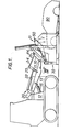
- the crusher jaw mechanism 11 is mounted on a conventional track-laying tractor body 12 as used in a heavy duty front loading machine, provided with a diesel engine, a drive transmission, a hydraulic power supply and controls, and an operator's cab.
- a pair of parallel laterally spaced main lifting arms 13 extend forwardly on either side of the tractor body and engage mounting plates 16 on the crusher jaws by means of pivot pins 17.
- the arms 13 pivot on the tractor body so that they can be raised and lowered thereon by hydraulic piston and cylinder assemblies 15 associated with each arm, in order to raise or lower the jaw mechanism.
- each main lifting arm 13 Associated with each main lifting arm 13 is a secondary linkage 20 controlling the tilt of the crusher jaws.
- the linkage 20 includes a link 21, pivoted at one end to the tractor body, at its mid-point to the main arm and at its other end to a hydraulic piston and cylinder assembly 22. This couples the link 21 to the mid-point of a further link 23, which has one end connected to the main arm to complete an approximately parallel linkage depending on the precise extension of the piston and cylinder 22.
- the other end of the link 23, remote from the main arm, is coupled through a bar 24 to the mounting plates 16 by means of a pivot pin 25, to complete a second substantially parallel linkage.
- the piston and cylinder 22 can be extended to tilt the crusher jaw mechanism towards its fully forward position, in which it would be tilted somewhat forward of the horizontal orientation shown in Fig. 1. Contraction of the assembly 22 would rotate the jaw mechanism towards its fully back position, in which it would be tilted back to an orientation that is near vertical or leaning back beyond vertical.
- the generally parallel nature of the secondary linkage 20 is such that raising or lowering the main lifting arms 13 does not substantially alter the tilt of the crusher jaw mechanism. Variations on this kind of linkage are well known in the front loading machine art for the purpose of raising or lowering a bucket, shovel or fork without tilting it, and are acceptable alternatives to the linkage shown.
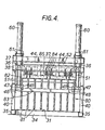
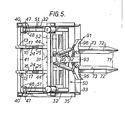
- the jaw mechanism as illustrated in Figs 1 to 7 comprises a rigid frame structure 30 including a crushing platform 31 and side plates 32, a pivoted upper jaw member 50 mounted in the frame between the side plates and over the platform, hydraulic drive means for the upper jaw member and an auxiliary rear gate 80 having an associated opening and closing mechanism.
- the frame structure 30 is a welded steel fabrication of plates and rectangular hollow sections.
- the platform 31, which forms part of a fixed lower jaw member, is carried on a framework comprising a front cross member (not shown) and a rear cross member 34, joined by side members 35 extending rearwardly beyond the platform and rear cross member. Further similar members provide reinforcement under the platform.
- a pair of front columns 36 stand one on either side of the platform and are joined at their top ends by an overhead main cross beam 37, and below the main beam by a secondary cross beam 38.
- a pair of shorter rear columns 40 stand one on each rear end of the side members 35 and are joined at their upper ends by a rear overhead cross beam 41.
- a pair of laterally spaced inclined mounting beams 44 extend from the rear overhead cross beam forwardly and upwardly to the main overhead cross beam, and carry the mounting plates 16.
- the space between the rear overhead cross beam 41 and the rear edge of the platform 31 is essentially unobstructed and defines a clear rear exit from the jaw mechanism, bounded at either side by the rear columns 40 and the rear ends of the side members 35.
- the side members 35 also carry vertical side plates 32, which are reinforced by the columns 36 and 40. These side plates enclose the sides of the jaw mechanism. Each side plate has an outwardly flared front vertical edge 33 to assist in guiding a car body shell or the like into the jaws. In order to avoid a crushed body shell jamming in the jaws as a result of lateral spreading, the side plates are not parallel, but are set at a shallow angle such that the distance between them steadily increases from the front to the back of the jaw mechanism 11. Suitable angles are 1 or more on each side, between 1° and 2 0 or 3 0 being commonly adequate, which corresponds to arb outward displacement of the rear end of each side plate of about 1 cm. or more in every metre length.
- a guide ramp 70 is provided at the front edge of the platform 31.
- Mounted on the ramp ahead of the platform are a pair of laterally spaced forwardly extending fork tines 71 of inverted T section.
- the side flanges 72 of the tines taper in at their tips towards the upright web 73, each of which is tapered throughout its full length, rising from a point at the front tip, initially steeply and thereafter gradually to a highest point above the rear edge of the ramp and the front edge of the platform, and finally dropping sharply back to terminate at platform level.
- the upper jaw 50 comprises two pairs of parallel cranked arms 51 connected at the head of the jaw by a rectangular framework of beams 52 which provides support and reinforcement for a press plate 55 carried on the lower face of the framework.
- the rearmost crossbeam of the framework carries on its rear face, between the two pairs of cranked arms, a series of triangular auxiliary plates 56 angled upwards at about 45o and reinforced by gusset plates 57.
- the upper jaw is mounted in the rigid lower jaw frame structure 30 by means of pivot pins 47 which hold the rear ends of the cranked arms 51 in brackets 48 carried on the tops of the rear columns 40 and on the ends of-the rear overhead cross beam 41.
- Movement of the upper jaw in the frame structure 30 is controlled by a hydraulic cylinder 60 pivotally mounted between pairs of plates 61 at each end of the two forward cross beams 37 and 38.
- Piston rods 62 are connected to the head of the upper jaw above the press plate 55 by means of pins 63 located between each pair of cranked arms 51.
- the cylinders are mounted so that it is the expansion stroke of the piston that drives the press plate towards the platform 31, and the less powerful contraction stroke that raises the press plate thereafter.
- the cylinders are so positioned in the jaw mechanism that, on expansion to extend the piston rods, the approximate midpoint of the press plate in the upper jaw is thrust directly towards the approximate midpoint of the platform in the lower jaw, thereby maximising the efficiency* of the jaw as a crushing mechanism.
- the arms 51 in the upper jaw for carrying the press plate are cranked at an angle of 30-35 0 .
- the pins 47 about which the upper jaw rotates are set at a height of about 80 cm. above the level of the platform, and are about 1 m. from the rear edge of the press plate.
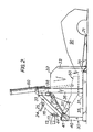
- the press plate is parallel with the platform when the upper jaw is closed to about 15 cm. from the platform (Fig. 2), which is considered a desirable thickness for the flattened body shell.
- the jaws can still crush and discharge a car body that has not been stripped of relatively incompressible components, such as engine, gearbox and axles, or even a complete car, because of the vertical clearance of 65-80 cm. below the rear cross beam 41 to platform level and the even greater total clearance of up to 1 m. between the rear cross beam and the rear edge of the platform.
- the upper jaw When the upper jaw is fully raised, there is a clearance of at least 90 cm. between the rear edge of the platform and the nearest parts of the upper jaw, which are points on the arms 51.
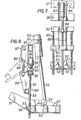
- the press plate When the upper jaw is raised to its maximum extent (Figs 1, 3 and 8), in which position the arms 51 are in abutment with the secondary cross beam 38, the press plate is angled upwards at about 45-50 0 to the horizontal and the triangular auxiliary plates 56 are near parallel to the platform, and substantially the whole of the upper jaw member 50 is above its axis of rotation, the press plate can act as a solid deflector which is capable of effecting a preliminary crushing of any high body shell, such as that of a large car or van, which is rammed into the jaws. As illustrated, the leading edge of the press plate in this position is about 140-150 cm. above the platform, and the rear edge is about 90 cm. above the platform.
- the jaw mechanism 11 is shown (Figs 1 to 7) fitted with an optional rear gate 80 between the front columns 36 behind the press plate.
- the gate is pivoted on hinge pins 85 in plates 84 mounted on the secondary cross beam 38, and can quickly be disconnected when not required by removing the hinge pins.
- the gate comprises an array of steel bars 81 extending downwardly from a horizontal beam 82 and reinforced by a second, lower, horizontal beam 83.
- the gate is actuated by a hydraulic cylinder 86 mounted in plates 87 carried on the two front cross beams 37 and 38, which has a piston rod 88 connected to a pair of plates 89 carried on the two gate beams 82 and 83.
- the gate is movable between a closed position (Figs 4, 6 and 7) in which the bars are substantially vertical when the platform is horizontal, and an open position (Figs 1 to 3), in which the bars are angled backwards as far as the rear cross beam 41 and leave the rear exit from the jaw mechanism substantially unobstructed.
- auxiliary plates 56 at the rear of the press plate 55 extend between each adjacent pair of bars 81 in the gate 80. These auxiliary plates prevent the upper jaw becoming jammed by small pieces of scrap which might otherwise get between the rear of the press plate and the gate when the gate if farthest away from the plate, i.e. when it is at the same height above the platform as the pivot pins 47, and preventing the plate from moving rearwards as it is closed further towards the platform.
- the jaw mechanism 11 is suitably made of steel, and may be of welded construction.
- the platform 31 and the press plate 55 are suitably of tough, abrasion-resistant steel plate; the tines 71 and the bars 81 may be of high yield, high tensile steel.
- Figs 1 to 3 The use of the crusher jaw mechanism to flatten car body shells is shown in Figs 1 to 3.
- the tractor is first driven forwards with the jaw mechanism 11 lowered and the platform 31 level or inclined slightly down at the front so that the tines 71 are run under the car body 90 to raise it to platform height.
- the tines act as two very' narrow ramps which probe under the car body which, if the wheels have been removed, will typically be resting on rough ground or concrete. Because they are much narrower than a single broad ramp, they are very much less likely to snag on the usual projections under the body shell, and if they do snag, they can be withdrawn by reversing the tractor and then run under the shell again in a slightly different location.
- the vertical webs 73 of the tines rise to a higher level than the platform so that as they are run under the body shell it is lifted high enough to allow any downwardly projecting or hanging parts of the shell to clear the leading edge of the platform, with assistance from the guide ramp 70 if necessary.
- Figure 1 shows the upper jaw 50 fully open at this stage; normally,'the upper jaw is only opened to raise the press plate sufficiently to admit the body shell to the jaws; the extent to which the upper jaw is opened accordingly depends on the size of the body shell.
- the initial impact of the angled press plate on the front of the shell may cause some preliminary crushing, and establishes that the shell is correctly located on the platform.
- the tractor is then halted and the press plate closed (Fig. 2), flattening the front end of the body shell 90 in one single action, then reopened; the tractor is again run forward until an uncrushed part of the body shell abuts the press plate; after crushing again in a single movement, opening the jaw and running the tractor forward again, the body shell will probably be far enough over the tines 71 and on to the platform 31 to remain in the jaw mechanism when it is then raised and tilted back to allow gravity to slide the body shell further back into the jaws (Fig. 3).
- the last sections of the body shell can be crushed with its leading end resting on the
- the tines 71 can be used to stack two or three such treated shells together, and they can all be flattened together in the jaws in the same manner as previously described.
- the throughput rate of the jaw mechanism is governed largely by the hydraulic pump capacity.
- An oil flow of 180 l./min. can enable 15 to 20 car body shells per hour to be flattened. This rate can be doubled at double the oil flow.
- a skilled operator can achieve very high throughput rates.
- Fig. 5 shows an engine grab 91 pivotally mounted in a bracket 92 on the front edge of the upper jaw member 50.
- a hydraulic ram (not visible in the drawing) located behind the bracket 92 acts to tilt a body member 93, which carries pincer grab jaws 96 powered by two hydraulic rams 95, between a forward lowered operative position and a rearward retracted position.
- a car engine can be removed by opening the car bonnet (hood) with one of the tines 71, positioning the tines above the car wings on either side of the engine compartment, tilting the engine grab forward into its operative position, lowering the upper jaw member 50 to insert the grab into the engine compartment, closing the grab jaws 96 to grip the engine, and opening the jaw mechanism to pull the engine and any attatched car transmission components from the car body while holding the body shell down with the tines.
- the hydraulic piston and cylinder assemblies used in the machine are all double acting, and can accordingly be driven and controlled on both their expansion and contraction srokes. Hydraulic power is taken from an oil pump in the tractor, and controlled from the cab, in the same way as in a conventional front loading machine.
- the flattened scrap produced by the jaw mechanism is in a condition that is suitable both for economical transportation and for fragmentisation, for example after cooling in liquid nitrogen, as a preliminary to reclamation of the different valuable materials contained in it.
- Fig. 8 illustrates an alternative method of using the crusher jaw mechanism 11.
- the mechanism is carried on a bed 100 mounted over the chassis 102 of a truck.
- the jaw mechanism is positioned over the back axle of the truck, facing forwards.
- a steel ramp 104 is provided ahead of the jaws, sloping downwardly from above the driver's cab 106 to an entry ramp 108 of shallower incline leading on to the platform 31 in the jaws.
- the jaw mechanism is in most respects as previously described, except that it lacks the inclined mounting beams 44, the rear gate 80, the front tines 71 and the entry ramp 70. It is however provided with a rear extension 112 to both its sides, which forms a base for a gantry 114 which carries a loading grab 116, and a seat 118 and hydraulic controls 120 for the crusher mechanism operator over the rear exit from the jaws.
- the loading grab 116 has a 360 turning capability, has a hydraulic articulated boom 122 and carries a swivelling grapple 124 for picking up and moving each car body shell 90.
- Steadying jacks 126 are provided under the rear of the bed 100. Sliding bars can be run out from under the rear of the bed to form a table 127, supported by jacks 128.
- a hydraulic oil pump 110 is located under the ramp 104 for providing the necessary power and oil flow for the various hydraulic mechanisms.
- a pump can be run from a power take-off point on the truck engine.
- the flattening action of the jaw mechanism is as previously described. It is, however, more mobile than when carried on a front loading machine, in that it can more readily be driven on the public roads from one scrapyard to another.
- the grab 116 can perform all the necessary functions of picking up a body shell 90, placing it on the ramp 104 as shown in Fig. 8, pushing it into the jaws and pulling it out of the jaws on to the table 127, and finally unloading the flattened shell on to a stack or on to a transporter.
- the entry ramps 104 and 108 are not essential, especially if the pump 110'is located elsewhere.
- the bed 100 can be a demountable bed of a kind that is known per se; in such a case, the bed can be offloaded from the truck chassis 102 complete with all the flattening equipment, including the jaw mechanism 11, the loading grab 116 and the hydraulic pump 110, which can then be worked in a static location while the truck continues to be used to transport fresh body shells to the offloaded flattener and to remove the flattened shells when a full load has been assembled. The grab 116 is then used to load and unload the truck as well as to feed the jaw mechanism.
- the loading grab is itself not essential in a demountable crusher jaw, because when the jaw has been offloaded it is then relatively simple to use other means for feeding the flattener, such as a winch or the like for pulling car body shells through the jaws or a ram or suitable vehicle for pushing them through.
- the jaw mechanism 11 can be used in this way without any need to provide for its transport on the truck.
- Another alternative arrangement on the truck without any need for the ramps 104 and 108, and either without the loading grab or with it relocated to the side of the bed 100, is to provide a tipping mechanism for the bed of a kind that is known per se; in this case, once a body shell has been loaded on to the bed in front of the open jaws, the front of the bed is raised and the shell is flattened in the usual way, relying on gravity to draw it through the jaw mechanism between flattening steps.
- the rear gate 80 may also be used for crushing light scrap.
- the jaw mechanism it is not essential for the jaw mechanism to be operator controlled at all times. It may be provided with automatic control means, e.g. limit switches, to reverse the upper jaw movement at the end of each stroke, in which case the operator can concentrate on supplying the body shells to the jaws.
- automatic control means e.g. limit switches
Landscapes
- Engineering & Computer Science (AREA)
- Mechanical Engineering (AREA)
- Crushing And Grinding (AREA)
- Disintegrating Or Milling (AREA)
Applications Claiming Priority (4)
| Application Number | Priority Date | Filing Date | Title |
|---|---|---|---|
| GB8039004 | 1980-12-05 | ||
| GB8039004 | 1980-12-05 | ||
| GB8119865 | 1981-06-26 | ||
| GB8119865 | 1981-06-26 |
Publications (2)
| Publication Number | Publication Date |
|---|---|
| EP0053930A2 true EP0053930A2 (de) | 1982-06-16 |
| EP0053930A3 EP0053930A3 (de) | 1983-01-05 |
Family
ID=26277734
Family Applications (2)
| Application Number | Title | Priority Date | Filing Date |
|---|---|---|---|
| EP81305745A Ceased EP0053930A3 (de) | 1980-12-05 | 1981-12-04 | Verdichtungsvorrichtung für Schrott und dergleichen und Verdichtungsverfahren |
| EP81305744A Withdrawn EP0053929A3 (de) | 1980-12-05 | 1981-12-04 | Fahrbare Verdichtungsvorrichtung und Verdichtungsverfahren |
Family Applications After (1)
| Application Number | Title | Priority Date | Filing Date |
|---|---|---|---|
| EP81305744A Withdrawn EP0053929A3 (de) | 1980-12-05 | 1981-12-04 | Fahrbare Verdichtungsvorrichtung und Verdichtungsverfahren |
Country Status (3)
| Country | Link |
|---|---|
| US (2) | US4442766A (de) |
| EP (2) | EP0053930A3 (de) |
| CA (2) | CA1187328A (de) |
Cited By (2)
| Publication number | Priority date | Publication date | Assignee | Title |
|---|---|---|---|---|
| AU600951B2 (en) * | 1986-04-07 | 1990-08-30 | Roy E. Labounty | Auto body crushing device |
| EP0785063A1 (de) * | 1996-01-19 | 1997-07-23 | Metaalbedrijf Busschers B.V. | Handhabungsvorrichtung für Kraftfahrzeugkarosserien |
Families Citing this family (16)
| Publication number | Priority date | Publication date | Assignee | Title |
|---|---|---|---|---|
| GB8908111D0 (en) * | 1989-04-11 | 1989-05-24 | Empteezy Ltd | Baler/compactor |
| US5373782A (en) * | 1994-04-28 | 1994-12-20 | Stewart; Wilbur | Car crushing and loading attachment for front loader |
| US5467704A (en) * | 1994-09-02 | 1995-11-21 | Alaron Corporation | Waste container reformer and method for reforming waste containers |
| GB9707289D0 (en) * | 1997-04-10 | 1997-05-28 | Graham Mining Limited | Portable crusher |
| GB2338917B (en) * | 1998-07-02 | 2000-11-08 | Langtons | Compacting device |
| RU2223177C2 (ru) * | 2002-02-06 | 2004-02-10 | Закрытое акционерное общество "Втормет" | Устройство для утилизации металлической бочкотары |
| US7024992B2 (en) * | 2002-08-16 | 2006-04-11 | Johnson Robert M | Mobile side-load metal crushing device |
| US7258710B2 (en) * | 2004-04-29 | 2007-08-21 | Advanced Cleanup Technologies, Inc. | Maritime emissions control system |
| US8808415B2 (en) | 2008-02-01 | 2014-08-19 | Sal Caro | Exhaust intake bonnet (EIB) for maritime emissions control system |
| US7992814B2 (en) * | 2008-04-10 | 2011-08-09 | Terex Usa, Llc | Mobile system and method for crushing rock while isolating electronic components from excessive vibration |
| US8578846B2 (en) * | 2008-11-03 | 2013-11-12 | Got Green?, LLC | Trash receptacle for collecting and compacting waste and related method of use |
| US7886660B1 (en) * | 2008-11-03 | 2011-02-15 | Sherwood Christopher R | System and trash receptacle for collecting and compacting trash |
| US8075651B2 (en) * | 2009-01-21 | 2011-12-13 | Sal Caro | Ellipsoid exhaust intake bonnet (EIB) for maritime emissions control system |
| KR100907260B1 (ko) | 2009-03-31 | 2009-07-10 | 고정수 | 천정 이동식 폐차 해체장치 |
| US8402746B2 (en) | 2010-05-03 | 2013-03-26 | John Powell | Exhaust gas capture system for ocean going vessels |
| FR3048370B1 (fr) * | 2016-03-03 | 2018-03-02 | Indra Sas | Systeme transportable et energise pour le demontage destructif de vehicules automobiles hors d’usage |
Family Cites Families (15)
| Publication number | Priority date | Publication date | Assignee | Title |
|---|---|---|---|---|
| US2616312A (en) * | 1949-04-25 | 1952-11-04 | Dempster Brothers Inc | Precompressor for baling presses |
| US2932244A (en) * | 1953-06-30 | 1960-04-12 | George Maddox | Portable hydraulic baling machine |
| US2875912A (en) * | 1956-01-23 | 1959-03-03 | Albert W Thresher | Attachment for a lift truck |
| US3242851A (en) * | 1964-04-13 | 1966-03-29 | Henry C Brawley | Mobile baling apparatus |
| US3266413A (en) * | 1965-03-22 | 1966-08-16 | Al Jon Inc | Car crushing machine |
| US3275172A (en) * | 1965-05-04 | 1966-09-27 | Wrex All Implements Inc | Wrecking and loading tool for use with a back hoe |
| US3273493A (en) * | 1965-10-13 | 1966-09-20 | Logemann Brothers Co | Apparatus for processing scrap material |
| US3413914A (en) * | 1966-06-03 | 1968-12-03 | Henry V Gonzales | Junked metal compressing smasher |
| DE1627829B1 (de) * | 1967-06-01 | 1971-08-26 | Keller & Knappich Gmbh | Auf einem Fahrzeug angeordnete Presse |
| US3615084A (en) * | 1969-01-08 | 1971-10-26 | Fidelis J Wasinger | Process and apparatus for salvaging junk material |
| US3651754A (en) * | 1969-08-25 | 1972-03-28 | Sheldon R Forest | Compacting and forming apparatus |
| DE2125543A1 (de) * | 1971-05-22 | 1972-12-07 | Wackenhut, Ernst, 7270 Nagold | Schrottpresse |
| US3763772A (en) * | 1972-06-28 | 1973-10-09 | Elina Baker | Multiple-pass crushing device |
| SE373065B (de) * | 1973-03-19 | 1975-01-27 | Hellbergs Mek Verkstad Ab | |
| US3942430A (en) * | 1974-06-10 | 1976-03-09 | David Roger Day | Trash compactor |
-
1981
- 1981-12-01 US US06/326,421 patent/US4442766A/en not_active Expired - Fee Related
- 1981-12-01 US US06/326,420 patent/US4441415A/en not_active Expired - Fee Related
- 1981-12-04 EP EP81305745A patent/EP0053930A3/de not_active Ceased
- 1981-12-04 EP EP81305744A patent/EP0053929A3/de not_active Withdrawn
- 1981-12-07 CA CA000391623A patent/CA1187328A/en not_active Expired
- 1981-12-07 CA CA000391624A patent/CA1187329A/en not_active Expired
Cited By (2)
| Publication number | Priority date | Publication date | Assignee | Title |
|---|---|---|---|---|
| AU600951B2 (en) * | 1986-04-07 | 1990-08-30 | Roy E. Labounty | Auto body crushing device |
| EP0785063A1 (de) * | 1996-01-19 | 1997-07-23 | Metaalbedrijf Busschers B.V. | Handhabungsvorrichtung für Kraftfahrzeugkarosserien |
Also Published As
| Publication number | Publication date |
|---|---|
| EP0053929A3 (de) | 1983-01-05 |
| EP0053930A3 (de) | 1983-01-05 |
| CA1187329A (en) | 1985-05-21 |
| EP0053929A2 (de) | 1982-06-16 |
| US4442766A (en) | 1984-04-17 |
| US4441415A (en) | 1984-04-10 |
| CA1187328A (en) | 1985-05-21 |
Similar Documents
| Publication | Publication Date | Title |
|---|---|---|
| US4441415A (en) | Crusher for scrap metal and the like | |
| US5080548A (en) | Trailer dumper | |
| US5562390A (en) | Detachable truck body and handling mechanism | |
| CA1041781A (en) | Post driving machine | |
| US7300239B2 (en) | Hoist for loading and unloading objects on a truck bed | |
| US4310279A (en) | Trash handling system | |
| US3323837A (en) | Powered, load ejecting wheelbarrow | |
| US2932244A (en) | Portable hydraulic baling machine | |
| WO1988008368A1 (en) | Auto body crushing device | |
| US4934896A (en) | Refuse collection apparatus and method | |
| EP1068015B1 (de) | Anlage zur materialbehandlung | |
| US6571693B1 (en) | Vehicle recycling system and method | |
| US4660469A (en) | Shear system | |
| US4263797A (en) | Method of reclaiming used railroad spikes | |
| US3859910A (en) | Demolition device | |
| US4204789A (en) | Pass through hay bale retriever | |
| US3413914A (en) | Junked metal compressing smasher | |
| US4241653A (en) | Bank out module builder with unloading mechanism | |
| US4273497A (en) | Refuse storage and discharge apparatus | |
| CN110682946B (zh) | 一种果园果箱装卸运输车 | |
| EP0198838B1 (de) | Ladungstransportierendes kipperfahrzeug | |
| US3235983A (en) | Earth moving apparatus | |
| US3905497A (en) | Automated refuse collection vehicle | |
| US4054301A (en) | Waste collection system and apparatus | |
| US4635544A (en) | Module builder with a flared top and with attachments |
Legal Events
| Date | Code | Title | Description |
|---|---|---|---|
| PUAI | Public reference made under article 153(3) epc to a published international application that has entered the european phase |
Free format text: ORIGINAL CODE: 0009012 |
|
| AK | Designated contracting states |
Designated state(s): AT BE CH DE FR GB IT LU NL SE |
|
| PUAL | Search report despatched |
Free format text: ORIGINAL CODE: 0009013 |
|
| AK | Designated contracting states |
Designated state(s): AT BE CH DE FR GB IT LI LU NL SE |
|
| 17P | Request for examination filed |
Effective date: 19830521 |
|
| STAA | Information on the status of an ep patent application or granted ep patent |
Free format text: STATUS: THE APPLICATION HAS BEEN REFUSED |
|
| 18R | Application refused |
Effective date: 19850428 |