EP0053881A1 - Mass transfer apparatus - Google Patents
Mass transfer apparatus Download PDFInfo
- Publication number
- EP0053881A1 EP0053881A1 EP81305377A EP81305377A EP0053881A1 EP 0053881 A1 EP0053881 A1 EP 0053881A1 EP 81305377 A EP81305377 A EP 81305377A EP 81305377 A EP81305377 A EP 81305377A EP 0053881 A1 EP0053881 A1 EP 0053881A1
- Authority
- EP
- European Patent Office
- Prior art keywords
- permeable element
- tape
- fluid
- axis
- permeable
- Prior art date
- Legal status (The legal status is an assumption and is not a legal conclusion. Google has not performed a legal analysis and makes no representation as to the accuracy of the status listed.)
- Granted
Links
Images


Classifications
-
- B—PERFORMING OPERATIONS; TRANSPORTING
- B01—PHYSICAL OR CHEMICAL PROCESSES OR APPARATUS IN GENERAL
- B01J—CHEMICAL OR PHYSICAL PROCESSES, e.g. CATALYSIS OR COLLOID CHEMISTRY; THEIR RELEVANT APPARATUS
- B01J19/00—Chemical, physical or physico-chemical processes in general; Their relevant apparatus
- B01J19/18—Stationary reactors having moving elements inside
- B01J19/1806—Stationary reactors having moving elements inside resulting in a turbulent flow of the reactants, such as in centrifugal-type reactors, or having a high Reynolds-number
-
- B—PERFORMING OPERATIONS; TRANSPORTING
- B01—PHYSICAL OR CHEMICAL PROCESSES OR APPARATUS IN GENERAL
- B01D—SEPARATION
- B01D11/00—Solvent extraction
- B01D11/04—Solvent extraction of solutions which are liquid
- B01D11/0446—Juxtaposition of mixers-settlers
- B01D11/0461—Juxtaposition of mixers-settlers mixing by counter-current streams provoked by centrifugal force
-
- B—PERFORMING OPERATIONS; TRANSPORTING
- B01—PHYSICAL OR CHEMICAL PROCESSES OR APPARATUS IN GENERAL
- B01D—SEPARATION
- B01D3/00—Distillation or related exchange processes in which liquids are contacted with gaseous media, e.g. stripping
- B01D3/14—Fractional distillation or use of a fractionation or rectification column
- B01D3/30—Fractionating columns with movable parts or in which centrifugal movement is caused
-
- B—PERFORMING OPERATIONS; TRANSPORTING
- B01—PHYSICAL OR CHEMICAL PROCESSES OR APPARATUS IN GENERAL
- B01D—SEPARATION
- B01D47/00—Separating dispersed particles from gases, air or vapours by liquid as separating agent
- B01D47/16—Apparatus having rotary means, other than rotatable nozzles, for atomising the cleaning liquid
-
- B—PERFORMING OPERATIONS; TRANSPORTING
- B01—PHYSICAL OR CHEMICAL PROCESSES OR APPARATUS IN GENERAL
- B01D—SEPARATION
- B01D53/00—Separation of gases or vapours; Recovering vapours of volatile solvents from gases; Chemical or biological purification of waste gases, e.g. engine exhaust gases, smoke, fumes, flue gases, aerosols
- B01D53/14—Separation of gases or vapours; Recovering vapours of volatile solvents from gases; Chemical or biological purification of waste gases, e.g. engine exhaust gases, smoke, fumes, flue gases, aerosols by absorption
- B01D53/18—Absorbing units; Liquid distributors therefor
-
- B—PERFORMING OPERATIONS; TRANSPORTING
- B01—PHYSICAL OR CHEMICAL PROCESSES OR APPARATUS IN GENERAL
- B01J—CHEMICAL OR PHYSICAL PROCESSES, e.g. CATALYSIS OR COLLOID CHEMISTRY; THEIR RELEVANT APPARATUS
- B01J19/00—Chemical, physical or physico-chemical processes in general; Their relevant apparatus
- B01J19/0053—Details of the reactor
- B01J19/0066—Stirrers
-
- B—PERFORMING OPERATIONS; TRANSPORTING
- B01—PHYSICAL OR CHEMICAL PROCESSES OR APPARATUS IN GENERAL
- B01J—CHEMICAL OR PHYSICAL PROCESSES, e.g. CATALYSIS OR COLLOID CHEMISTRY; THEIR RELEVANT APPARATUS
- B01J19/00—Chemical, physical or physico-chemical processes in general; Their relevant apparatus
- B01J19/0053—Details of the reactor
- B01J19/0073—Sealings
Definitions
- This invention relates to apparatus for effecting mass transfer between two fluid phases, at least one of which is a liquid, and to the use of such apparatus.
- mass transfer we mean transfer to a first fluid phase from a second fluid phase, or vice versa, of at least a proportion of a substance which is a solute for the first fluid phase wherein the first fluid phase (a) is a liquid, (b) is substantially immiscible with the second fluid phase and (c) has a density greater than that of the second fluid phase.
- Absorption and distillation, processes which are widely used in the chemical and petrochemical industries, are typical mass transfer processes.
- the rate of mass transfer may also be improved by (a) employing a permeable element which comprises strands, fibres, fibrils or filaments having a so-called "equivalent diameter" of less than about 150 microns and/or (b) rotating the permeable element to subject the fluids flowing through the pores thereof to a mean acceleration of more than about 5000 metres seconds-2.
- the permeable element is in the form of a disc or annulus and comprises an agglomeration of fibres, or a loosely wound tape, although the permeable element appears substantially uniform and homogeneous prior to and subsequent to rotation at high speed in the aforementioned apparatus, during rotation at high speed there is a tendency for portions of the permeable element to move relative to other portions thereof such that gaps are generated in the permeable element, the apparatus becomes unbalanced, the voidage of the permeable element alters and the performance of the apparatus deteriorates.
- the present invention provides apparatus for effecting mass transfer between two fluid phases, at least the first of which is a liquid, which apparatus comprises an at least substantially annular permeable element (as hereinafter defined) which is rotatable about its axis of symmetry, means to charge the first fluid to the permeable element, means to charge the second fluid to the permeable element, and means to discharge at least one of the fluids or a derivative thereof from the permeable element characterised in that the permeable element is formed by winding a tape under tension around the said axis and in a plane transverse to the said axis, and anchoring the tape to maintain it under tension.
- an at least substantially annular permeable element as hereinafter defined
- the present invention further provides a process for effecting mass transfer between two fluid phases, at least the first of which is a liquid, which process comprises charging the, said fluids to an at least substantially annular permeable element (as hereinafter defined), rotating the permeable element about its axis of symmetry such that the fluids are subjected to a mean acceleration of at least 150 metres seconds- 2 as they flow through the pores of the permeable element with the first fluid flowing radially outwards away from the said axis and collecting at least a portion of one of the fluids or a derivative thereof discharged from the permeable element characterised in that the permeable element is formed by winding a tape under tension around the said axis and in a plane transverse to the said axis and maintaining it under tension.
- an at least substantially annular permeable element as hereinafter defined
- the direction in which the tape is wound is such that rotation of the permeable element in operation of the apparatus of the present invention will tend to tighten the tape around the axis of the permeable element.
- permeable element we mean an element of apparatus according to the present invention which (a) allows passage of the fluids through the pores thereof, the wall surfaces of the said pores providing a tortuous and substantially continuous path over which the fluids may flow, and (b) is rotatable to subject the'fluids flowing therethrough to a mean acceleration as hereinafter defined of at least 150 metres seconds -2 .
- tape we include tapes, ribbons, and strips, etc.
- the tape may be a single layer or a plurality of layers, e.g. formed by collapsing a tube or so-called "stocking". Whilst the tape is preferably formed from fibres, particularly preferably by knitting or weaving, more particularly preferably by knitting, we do not exclude the possibility that it may be formed from non- fibrous material, e.g. by punching holes in a suitable metal foil.
- fibres we include fibres, fibrils, filaments, strands, etc., and mixtures thereof.
- the permeable element of apparatus of the present invention comprises a tape which is formed by knitting one or more suitable fibres the tape is wound under a tension which is at least just above, say 5% above, the stop stress of the tape and preferably at least double the stop stress.
- stop stress we mean the maximum tensile stress to which the tape can be subjected without at least straining the aforementioned one or more suitable fibres. Where a tensile stress below the stop stress is applied to a knitted tape to increase the length thereof the loops of the knitted tape distort and elongate and then relax when the tensile stress is released.
- a tensile stress above the stop stress is applied to a knitted tape to increase the length thereof the aforementioned one or more suitable fibres is (are) strained and, compared with the knitted tape at tensile stresses below the stop stress, there is a substantial increase in tensile stress to obtain a particular increase in length of the knitted tape and the tape does not relax to its original length when the tensile stress is released.
- Mean acceleration a m is defined by the equation: where N is the rotational speed of the permeable element about the axis of revolution in revolutions per minute, r o is the distance in metres from the aforementioned axis to the radially inner surface of the permeable element, and r l is the distance in metres from the aforementioned axis to the radially outer surface of the permeable element.
- the permeable element used in apparatus of the present invention has a voidage of at least 90%.
- the permeable element has a voidage of at least 93% and more particularly preferably the permeable element has a voidage of at least 95%.
- the permeable element used in apparatus of the present invention has an interfacial area of at least 1500 metres 2 /metres 3 , more preferably at least 3000 metres 2 /metres3.
- interfacial area we mean the surface area of the permeable element which the fluids may contact per unit volume of permeable element.
- voidage we mean the percentage of the volume of the annulus which forms the permeable element which is free space.
- fluid we mean a substance or a mixture of substances, which is a gas or a liquid at the conditions of temperature and pressure at which the apparatus of the invention is operated.
- the second fluid is a gas it may be one gas or a mixture of gases;
- the first fluid and/or the second fluid may be a neat liquid or may be a solution of one or more solutes in the liquid, which solute may be a gas, liquid or solid.
- the mean acceleration as hereinbefore defined, to which the fluids are subjected in apparatus according to the present invention is preferably greater than about 5000 metres seconds -2 , since on increasing the mean acceleration to more than about 5000 metres seconds- 2 , there is often a surprising increase in the rate of mass transfer.
- the permeable element in apparatus according to the present invention is formed from a tape which comprises fibres, preferably the fibres are monofilaments, particularly preferably monofilaments having an equivalent diameter of less than about 150 microns.
- the permeable element may be formed from a tape which is knitted from wire monofilament of 120 microns diameter.
- Equivalent diameter d e is defined by the equation: ("Chemical Engineering, Volume 1, Second Edition” by Coulson and Richardson, page 210).
- the cross-sectional shape of fibres, where they are employed, may be for example, circular, triangular, cruciform or triskellion, although preferably it is circular.
- the outer diameter of the annulus is typically in the range 25 cm to 5 metres, and the inner diameter is typically in the range 5 cm to 1 metre.
- the tape from which the permeable element of apparatus according to the present invention is wound may be formed from any material which has the mechanical strength to withstand the stress generated in the material during rotation of the permeable element at the rotational speeds employed.
- the material is resistant to attack by or reaction with the fluids with which it may be in physical contact.
- materials from which the permeable element may be formed include inter alia glass, plastics, or metals, particularly chemically resistant metals, e.g. stainless steel, nickel, titanium or tantalum. It is often preferred that the material is metallic.
- the tape may be a composite of two or more materials in an appropriate disposition.
- the tape may be formed by knitting together steel wire and a yarn of polytetrafluoroethylene fibres to form a tube and then collapsing the tube.
- the permeable element may comprise one tape or a plurality of tapes. Where a plurality of tapes wound under tension are used to provide a permeable element they may be in the form of concentric annuli. For example, an annulus of wire mesh may be surrounded by an annulus of woven glass tape. Alternatively, a plurality of tapes, e.g. two, may be wound simultaneously such that the permeable element comprises, where two tapes are employed, alternate rings of the two tapes. Where a plurality of tapes are wound simultaneously it is often preferred that only one of them is wound under tension.
- the permeable element in apparatus of the present invention is often preferably disposed in a rotatable member.
- the permeable element may be disposed throughout or in a proportion of the rotatable member.
- the size of the permeable element and its disposition in the rotatable member may be determined by the density and the interfacial area of the permeable element and by the flow characteristics of the fluids.
- the permeable element is disposed in a portion of the rotatable member it is often preferred that the permeable element is disposed in a radially outer portion of the rotatable member since as the distance from the axis increases, the magnitude of the centrifugal forces which operate on the fluid to form a layer increases and hence the thickness of the layer is decreased.
- the rotatable member where it is employed, may be constructed of any material which has (a) the mechanical strength to withstand the stress generated.in the material during rotation of the rotatable member at the rotational speeds employed and (b) the corrosion resistance to tolerate the environments with which the rotatable member may be in contact during use.
- Typical materials from which the rotatable member may be constructed include inter alia stainless steel, mild steel, brass, aluminium, nickel, Monel. Choice of a suitable material will present no problem to those skilled in the art.
- the permeable element is formed by winding at least one tape under tension on a suitable former, e.g. a mandrel or spool, and preferably the aforesaid former is at least a component of the rotatable member.
- a suitable former e.g. a mandrel or spool
- the aforesaid former is at least a component of the rotatable member.
- the rotatable member may be a hollow disc having a removable lid and provided with three or more, typically six, pins symmetrically disposed adjacent the axis thereof, around which combination of pins the tape may be wound. It will be appreciated that, where the tape is wound around a combination of symmetrically disposed pins, as the number of pins employed is increased the inner face.of the permeable element tends to become cylindrical.
- the tape which has been wound under tension to form a permeable element for use in apparatus of the present invention is anchored such that it is maintained under a tension which is at least a substantial portion of the tension under which it was wound and which is preferably substantially the tension under which it was wound.
- the outer end of the tape is attached to the body of the permeable element by suitable means.
- one or more pins may be forced through the outer end of the tape and thence through the layers of tape and attached to the mandrel on which the tape was wound.
- the second fluid may have to be at pressure greater than that of the first fluid at the position on the permeable element at which the permeable is charged with the second fluid.
- means to deliver the first fluid to the permeable element typically comprises an orifice in the rotatable member through which the fluid may flow.
- the delivery means is conveniently axially disposed, although we do not exclude the possibility that it may be located intermediate the axis of rotation and the means to charge the second fluid to the permeable element.
- the first fluid is a mixture of components, these may be delivered to the permeable element through the same or separate delivery means, e.g. they may be delivered through concentric tubes.
- means to discharge the first fluid or a component or derivative thereof from the rotatable member typically comprises a multiplicity of orifices in the periphery of the rotatable member distant the axis of rotation, through which orifices the fluid may issue as a spray.
- means to discharge the second fluid or a component or derivative thereof from the rotatable member typically comprises one or more orifices in the rotatable member through which the second fluid or a component or derivative thereof may flow.
- the rotatable member is a hollow disc in which an annular permeable element is disposed the orifice is conveniently axially disposed.
- the permeable element, or the rotatable member, where it is employed is mounted in a stationary fluid-collecting means, e.g. a housing or casing, in which fluid-collecting means the fluid or component or derivative thereof which is discharged from the permeable element distant the axis of rotation may be collected.
- a stationary fluid-collecting means e.g. a housing or casing
- the stationary fluid-collecting means is in the form of a sealed housing the second fluid may be charged thereto and thence to the permeable element, e.g. via suitably disposed orifices in the rotatable member.
- the first fluid and/or the second fluid where it is a liquid, preferably "wets" substantially the whole of the wall surface of the pores of the permeable element. Wetting of the permeable element will depend to a degree on dynamic factors but will be assisted if it is favoured by equilibrium wetting conditions. Thus, a fluid having a small interfacial tension with the permeable element will tend to displace from the surface of the pores of the permeable element a fluid having a large interfacial tension with the permeable element, which displacement process is assisted by a small interfacial tension between the two fluids.
- the surface of the pores of the permeable element is preferably coated with a wetting agent, or a wetting agent is preferably added to at least one of the fluids.
- a wetting agent is preferably added to at least one of the fluids.
- the first fluid is water and the pores of the permeable element have a hydrophobic surface, e.g. the permeable element comprises a mat of polytetrafluoroethylene fibres, suitable surfactants, e.g. sodium dodecylsulphate or a Monflur (RTM) surfactant, may be added to the water.
- suitable surfactants e.g. sodium dodecylsulphate or a Monflur (RTM) surfactant
- RTM Monflur
- a plurality of permeable elements each provided with suitable fluid-collecting means, typically a housing, although we do not exclude the possibility that a circumferential channel and associated removal means as hereinbefore described may be employed, may be joined in series fluid flow communication. It will be appreciated that suitable pumps where appropriate may be provided in the lines interconnecting adjacent permeable elements. Optionally the permeable elements are mounted along a common axis. While the fluids may flow co-currently through the series, it is often preferred that countercurrent flow operates.
- the apparatus according to the present invention may be employed in inter alia absorption, desorption, counter current extraction, distillation and homogenisation processes.
- Apparatus of the present invention in which the permeable element comprises a knitted tape wound under tension gives better mass transfer and flooding character. istics than apparatus in which the permeable element comprises a similar knitted tape which has been loosely wound.
- a rotatable element 1 in the form of a hollow disc comprising a base 2, cylindrical outer wall 3, which is provided with a multiplicity of orifices (not shown), and an annular top 4 is mounted upon a shaft 5 by means of which it is rotated in an anti-clockwise direction.
- an annular permeable element which has been formed by winding a tape under a desired tension around the six pins 7; the direction of winding of the tape is such that when the permeable element is mounted in the rotatable element the tape appears as a clockwise spiral running from the centre to the outside of the permeable element.
- the tape employed in the embodiment is knitted from a metallic monofilament and sold under the Registered Trade Mark "Knitmesh".
- the rotatable element is axially disposed within a generally cylindrical container 8, defining a chamber 9 and provided with conduits 10 and 11 for the introduction of gas and discharge of liquid respectively from the chamber 9.
- Liquid is introduced to the apparatus via liquid feed pipe 12, disposed axially with respect to the container 8, provided with a series of discharge slots 13 in its lower end, and concentric for a part of its length with a gas discharge pipe 14.
- a liquid seal 15 is provided on the top 4.
- liquid supplied by feed-pipe 12 is sprayed via slots 13 on to the inner face of the permeable element 6 through which it is forced radially outwards by centrifugal force.
- Gas enters the apparatus via the conduit 10; the liquid seal 15 prevents.the gas by-passing the permeable element 6 and it is forced through the pores of the permeable element 6 where it contacts the liquid.
- the liquid is discharged from the rotatable element via the orifices in outer wall 3, into chamber 9, from which it is drained via liquid discharge conduit 11.
- the gas is discharged from the permeable element 6 at its inner face and leaves the apparatus via gas discharge pipe 14.
- a tape was subjected to an increasing load until permanent elongation occurred and its stop stress was calculated.
- a further sample of the tape was wound, under an applied load which was greater than the load required to give the stop stress, on a mandrel formed by six pins attached in a suitable configuration to a steel base to form a permeable element of axial depth 2.3 cm, inner diameter 9.6 cm and outer diameter 21.6 cm.
- the outer end of the tape was anchored by attaching it to the body of the permeable element.
- the permeable elements were separately mounted in a hollow disc as illustrated in Figures 1 and 2, but having a transparent lid and were rotated at a mean acceleration of 10000 metres seconds- 2 whilst water, at a rate of 5 litres per minute, flowed through for 25 hours.
- the rotating permeable elements were viewed under a stroboscope and no separation of the layers of tape was observed.
- the annular permeable element prepared in Example 3 was mounted in a hollow disc as illustrated in Figures 1 and 2.
- the permeable element was rotated and water was charged to it to flow radially outwards through the pores thereof while "white-spot" nitrogen at 0.5 metres per minute was charged to the permeable element to flow radially inwards.
Abstract
Description
- This invention relates to apparatus for effecting mass transfer between two fluid phases, at least one of which is a liquid, and to the use of such apparatus.
- By "mass transfer" we mean transfer to a first fluid phase from a second fluid phase, or vice versa, of at least a proportion of a substance which is a solute for the first fluid phase wherein the first fluid phase (a) is a liquid, (b) is substantially immiscible with the second fluid phase and (c) has a density greater than that of the second fluid phase. Absorption and distillation, processes which are widely used in the chemical and petrochemical industries, are typical mass transfer processes.
- It is known from UK Patent Specification No. 757,149 that the rate of mass transfer between two fluid phases may be increased by subjecting the fluids to an acceleration up to approximately 2000 metres seconds-2 while they flow through conventional packing material in rotary mass transfer apparatus. Our European Patent Publication No. 2568A discloses that a further increase in the rate of mass transfer may be obtained by employing, in a rotary mass transfer apparatus, a permeable element having an interfacial area of at least 1500 metres metres3 and our European Patent Publication No. 20055A discloses that the rate of mass transfer may also be improved by (a) employing a permeable element which comprises strands, fibres, fibrils or filaments having a so-called "equivalent diameter" of less than about 150 microns and/or (b) rotating the permeable element to subject the fluids flowing through the pores thereof to a mean acceleration of more than about 5000 metres seconds-2.
- Where, in the aforementioned apparatus, the permeable element is in the form of a disc or annulus and comprises an agglomeration of fibres, or a loosely wound tape, although the permeable element appears substantially uniform and homogeneous prior to and subsequent to rotation at high speed in the aforementioned apparatus, during rotation at high speed there is a tendency for portions of the permeable element to move relative to other portions thereof such that gaps are generated in the permeable element, the apparatus becomes unbalanced, the voidage of the permeable element alters and the performance of the apparatus deteriorates.
- We have found that, where a permeable element in the shape of a disc or annulus is formed by winding a tape, such disadvantages may be at least alleviated by winding at least a first tape under tension in a plane perpendicular to the axis of rotation of the disc or annulus.
- Accordingly, the present invention provides apparatus for effecting mass transfer between two fluid phases, at least the first of which is a liquid, which apparatus comprises an at least substantially annular permeable element (as hereinafter defined) which is rotatable about its axis of symmetry, means to charge the first fluid to the permeable element, means to charge the second fluid to the permeable element, and means to discharge at least one of the fluids or a derivative thereof from the permeable element characterised in that the permeable element is formed by winding a tape under tension around the said axis and in a plane transverse to the said axis, and anchoring the tape to maintain it under tension.
- The present invention further provides a process for effecting mass transfer between two fluid phases, at least the first of which is a liquid, which process comprises charging the, said fluids to an at least substantially annular permeable element (as hereinafter defined), rotating the permeable element about its axis of symmetry such that the fluids are subjected to a mean acceleration of at least 150 metres seconds-2 as they flow through the pores of the permeable element with the first fluid flowing radially outwards away from the said axis and collecting at least a portion of one of the fluids or a derivative thereof discharged from the permeable element characterised in that the permeable element is formed by winding a tape under tension around the said axis and in a plane transverse to the said axis and maintaining it under tension.
- Preferably the direction in which the tape is wound, that is clockwise or anti-clockwise, is such that rotation of the permeable element in operation of the apparatus of the present invention will tend to tighten the tape around the axis of the permeable element.
- By "permeable element" we mean an element of apparatus according to the present invention which (a) allows passage of the fluids through the pores thereof, the wall surfaces of the said pores providing a tortuous and substantially continuous path over which the fluids may flow, and (b) is rotatable to subject the'fluids flowing therethrough to a mean acceleration as hereinafter defined of at least 150 metres seconds-2.
- Within the term "tape" we include tapes, ribbons, and strips, etc.
- The tape may be a single layer or a plurality of layers, e.g. formed by collapsing a tube or so-called "stocking". Whilst the tape is preferably formed from fibres, particularly preferably by knitting or weaving, more particularly preferably by knitting, we do not exclude the possibility that it may be formed from non- fibrous material, e.g. by punching holes in a suitable metal foil.
- Within the term "fibres" we include fibres, fibrils, filaments, strands, etc., and mixtures thereof.
- Where the permeable element of apparatus of the present invention comprises a tape which is formed by knitting one or more suitable fibres the tape is wound under a tension which is at least just above, say 5% above, the stop stress of the tape and preferably at least double the stop stress.
- By "stop stress" we mean the maximum tensile stress to which the tape can be subjected without at least straining the aforementioned one or more suitable fibres. Where a tensile stress below the stop stress is applied to a knitted tape to increase the length thereof the loops of the knitted tape distort and elongate and then relax when the tensile stress is released. Where a tensile stress above the stop stress is applied to a knitted tape to increase the length thereof the aforementioned one or more suitable fibres is (are) strained and, compared with the knitted tape at tensile stresses below the stop stress, there is a substantial increase in tensile stress to obtain a particular increase in length of the knitted tape and the tape does not relax to its original length when the tensile stress is released.
- It will be appreciated that the higher the tensile stress under which a tape is wound to form a permeable element for use in apparatus of the present invention the higher is the stress which the permeable element will withstand without the layers thereof separating in operation of the apparatus. It is often convenient to subject the tape to such a tensile stress that the width thereof is reduced to the axial depth which is desired for the permeable element. It will be appreciated that there is an upper limit to the tensile stress which a tape knitted from monofilaments will withstand before it breaks. We have found that, where the tape is knitted from monofilament of diameter less than 200 microns, the tensile stress at which the tape breaks is often less than ten times the stop stress and may, for example, be about five times the stop stress.
- Mean acceleration am is defined by the equation:

- Preferably the permeable element used in apparatus of the present invention has a voidage of at least 90%. Particularly preferably the permeable element has a voidage of at least 93% and more particularly preferably the permeable element has a voidage of at least 95%.
- Preferably the permeable element used in apparatus of the present invention has an interfacial area of at least 1500 metres2/metres3, more preferably at least 3000 metres2/metres3.
- By "interfacial area" we mean the surface area of the permeable element which the fluids may contact per unit volume of permeable element.
- By "voidage" we mean the percentage of the volume of the annulus which forms the permeable element which is free space.
- By "fluid" we mean a substance or a mixture of substances, which is a gas or a liquid at the conditions of temperature and pressure at which the apparatus of the invention is operated. For example, where the second fluid is a gas it may be one gas or a mixture of gases; the first fluid and/or the second fluid (where it is a liquid) may be a neat liquid or may be a solution of one or more solutes in the liquid, which solute may be a gas, liquid or solid.
- The mean acceleration as hereinbefore defined, to which the fluids are subjected in apparatus according to the present invention is preferably greater than about 5000 metres seconds-2, since on increasing the mean acceleration to more than about 5000 metres seconds-2, there is often a surprising increase in the rate of mass transfer.
- Where the permeable element in apparatus according to the present invention is formed from a tape which comprises fibres, preferably the fibres are monofilaments, particularly preferably monofilaments having an equivalent diameter of less than about 150 microns. For example, the permeable element may be formed from a tape which is knitted from wire monofilament of 120 microns diameter.
- Equivalent diameter de is defined by the equation:

- The cross-sectional shape of fibres, where they are employed, may be for example, circular, triangular, cruciform or triskellion, although preferably it is circular.
- In annular permeable elements for use in apparatus of the present invention, the outer diameter of the annulus is typically in the range 25 cm to 5 metres, and the inner diameter is typically in the
range 5 cm to 1 metre. - The tape from which the permeable element of apparatus according to the present invention is wound may be formed from any material which has the mechanical strength to withstand the stress generated in the material during rotation of the permeable element at the rotational speeds employed. Preferably the material is resistant to attack by or reaction with the fluids with which it may be in physical contact. Examples of materials from which the permeable element may be formed include inter alia glass, plastics, or metals, particularly chemically resistant metals, e.g. stainless steel, nickel, titanium or tantalum. It is often preferred that the material is metallic. Alternatively, the tape may be a composite of two or more materials in an appropriate disposition. For example, the tape may be formed by knitting together steel wire and a yarn of polytetrafluoroethylene fibres to form a tube and then collapsing the tube.
- The permeable element may comprise one tape or a plurality of tapes. Where a plurality of tapes wound under tension are used to provide a permeable element they may be in the form of concentric annuli. For example, an annulus of wire mesh may be surrounded by an annulus of woven glass tape. Alternatively, a plurality of tapes, e.g. two, may be wound simultaneously such that the permeable element comprises, where two tapes are employed, alternate rings of the two tapes. Where a plurality of tapes are wound simultaneously it is often preferred that only one of them is wound under tension.
- As the interfacial area for any particular permeable element is increased, the pressure drop across the permeable element increases and the possibility of fouling and flooding of the permeable element increases. Simple experiment will readily reveal a suitable permeable element for any desired speed of rotation and fluid combination.
- The permeable element in apparatus of the present invention is often preferably disposed in a rotatable member.
- Where a rotatable member is employed, the permeable element may be disposed throughout or in a proportion of the rotatable member. The size of the permeable element and its disposition in the rotatable member may be determined by the density and the interfacial area of the permeable element and by the flow characteristics of the fluids. Where the permeable element is disposed in a portion of the rotatable member it is often preferred that the permeable element is disposed in a radially outer portion of the rotatable member since as the distance from the axis increases, the magnitude of the centrifugal forces which operate on the fluid to form a layer increases and hence the thickness of the layer is decreased.
- The rotatable member, where it is employed, may be constructed of any material which has (a) the mechanical strength to withstand the stress generated.in the material during rotation of the rotatable member at the rotational speeds employed and (b) the corrosion resistance to tolerate the environments with which the rotatable member may be in contact during use. Typical materials from which the rotatable member may be constructed include inter alia stainless steel, mild steel, brass, aluminium, nickel, Monel. Choice of a suitable material will present no problem to those skilled in the art.
- Conveniently the permeable element is formed by winding at least one tape under tension on a suitable former, e.g. a mandrel or spool, and preferably the aforesaid former is at least a component of the rotatable member. For example, the rotatable member may be a hollow disc having a removable lid and provided with three or more, typically six, pins symmetrically disposed adjacent the axis thereof, around which combination of pins the tape may be wound. It will be appreciated that, where the tape is wound around a combination of symmetrically disposed pins, as the number of pins employed is increased the inner face.of the permeable element tends to become cylindrical.
- The tape which has been wound under tension to form a permeable element for use in apparatus of the present invention is anchored such that it is maintained under a tension which is at least a substantial portion of the tension under which it was wound and which is preferably substantially the tension under which it was wound. Conveniently the outer end of the tape is attached to the body of the permeable element by suitable means. For example, one or more pins may be forced through the outer end of the tape and thence through the layers of tape and attached to the mandrel on which the tape was wound.
- As the first fluid flows radially outwards through the rotating permeable element the pressure to which the first fluid is subjected increases. Thus, where countercurrent flow is employed, it will be appreciated that to charge the permeable element with the second fluid, the second fluid may have to be at pressure greater than that of the first fluid at the position on the permeable element at which the permeable is charged with the second fluid.
- Where the permeable element is supported in a rotatable member, means to deliver the first fluid to the permeable element typically comprises an orifice in the rotatable member through which the fluid may flow. Where the rotatable member is a hollow disc the delivery means is conveniently axially disposed, although we do not exclude the possibility that it may be located intermediate the axis of rotation and the means to charge the second fluid to the permeable element. Where the first fluid is a mixture of components, these may be delivered to the permeable element through the same or separate delivery means, e.g. they may be delivered through concentric tubes.
- Where a permeable element supported in a rotatable member is employed in apparatus according to the present invention, means to discharge the first fluid or a component or derivative thereof from the rotatable member typically comprises a multiplicity of orifices in the periphery of the rotatable member distant the axis of rotation, through which orifices the fluid may issue as a spray.
- Where a permeable element supported in a rotatable member is employed in apparatus according to the present invention means to discharge the second fluid or a component or derivative thereof from the rotatable member typically comprises one or more orifices in the rotatable member through which the second fluid or a component or derivative thereof may flow. Where the rotatable member is a hollow disc in which an annular permeable element is disposed the orifice is conveniently axially disposed.
- Conveniently, the permeable element, or the rotatable member, where it is employed, is mounted in a stationary fluid-collecting means, e.g. a housing or casing, in which fluid-collecting means the fluid or component or derivative thereof which is discharged from the permeable element distant the axis of rotation may be collected. Moreover, where the stationary fluid-collecting means is in the form of a sealed housing the second fluid may be charged thereto and thence to the permeable element, e.g. via suitably disposed orifices in the rotatable member.
- It will be appreciated that for the generation in the permeable element of a liquid surface of large area, the first fluid and/or the second fluid, where it is a liquid, preferably "wets" substantially the whole of the wall surface of the pores of the permeable element. Wetting of the permeable element will depend to a degree on dynamic factors but will be assisted if it is favoured by equilibrium wetting conditions. Thus, a fluid having a small interfacial tension with the permeable element will tend to displace from the surface of the pores of the permeable element a fluid having a large interfacial tension with the permeable element, which displacement process is assisted by a small interfacial tension between the two fluids. To improve the "wetting" of the permeable element the surface of the pores of the permeable element is preferably coated with a wetting agent, or a wetting agent is preferably added to at least one of the fluids. For example where the first fluid is water and the pores of the permeable element have a hydrophobic surface, e.g. the permeable element comprises a mat of polytetrafluoroethylene fibres, suitable surfactants, e.g. sodium dodecylsulphate or a Monflur (RTM) surfactant, may be added to the water. Where the first and second fluids are liquids it is often preferred that the wall surfaces of the pores are "wetted" preferentially by the first fluid.
- A plurality of permeable elements, each provided with suitable fluid-collecting means, typically a housing, although we do not exclude the possibility that a circumferential channel and associated removal means as hereinbefore described may be employed, may be joined in series fluid flow communication. It will be appreciated that suitable pumps where appropriate may be provided in the lines interconnecting adjacent permeable elements. Optionally the permeable elements are mounted along a common axis. While the fluids may flow co-currently through the series, it is often preferred that countercurrent flow operates.
- The apparatus according to the present invention may be employed in inter alia absorption, desorption, counter current extraction, distillation and homogenisation processes.
- Apparatus of the present invention in which the permeable element comprises a knitted tape wound under tension gives better mass transfer and flooding character. istics than apparatus in which the permeable element comprises a similar knitted tape which has been loosely wound.
- By better mass transfer characteristics we mean that the height of a transfer unit has been reduced and by better flooding characteristics we mean that flood points at least approach or in may instances are above the Sherwood-Lobo curve as defined in "
Chemical Engineeriì Volume 2", First Edition by Coulson and Richardson at page 411. - The invention will be further described by reference to the accompanying drawings, which show, by way of example only, apparatus for effecting mass transfe: between two fluid phases according to the present invention.
- Figure 1 is a longitudinal cross-section of a gas-absorber;
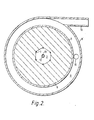
- Figure 2 is a transverse cross-section on the line AA of Figure 1; and
- Figures 3, 4 and 5 are diagrammatic representatio of portions of known permeable elements in operation.
- Referring firstly to Figures 1 and 2, a rotatable element 1 in the form of a hollow disc comprising a
base 2, cylindricalouter wall 3, which is provided with a multiplicity of orifices (not shown), and an annular top 4 is mounted upon ashaft 5 by means of which it is rotated in an anti-clockwise direction. Mounted symmetrically about the axis of rotation of the rotatable element 1 is an annular permeable element which has been formed by winding a tape under a desired tension around the sixpins 7; the direction of winding of the tape is such that when the permeable element is mounted in the rotatable element the tape appears as a clockwise spiral running from the centre to the outside of the permeable element. The tape employed in the embodiment is knitted from a metallic monofilament and sold under the Registered Trade Mark "Knitmesh". - The rotatable element is axially disposed within a generally
cylindrical container 8, defining achamber 9 and provided withconduits chamber 9. Liquid is introduced to the apparatus vialiquid feed pipe 12, disposed axially with respect to thecontainer 8, provided with a series ofdischarge slots 13 in its lower end, and concentric for a part of its length with a gas discharge pipe 14. Aliquid seal 15 is provided on the top 4. - In operation of the apparatus, liquid supplied by feed-
pipe 12 is sprayed viaslots 13 on to the inner face of thepermeable element 6 through which it is forced radially outwards by centrifugal force. Gas enters the apparatus via theconduit 10; theliquid seal 15 prevents.the gas by-passing thepermeable element 6 and it is forced through the pores of thepermeable element 6 where it contacts the liquid. The liquid is discharged from the rotatable element via the orifices inouter wall 3, intochamber 9, from which it is drained vialiquid discharge conduit 11. The gas is discharged from thepermeable element 6 at its inner face and leaves the apparatus via gas discharge pipe 14. - Various aspects of the present invention will now be described with reference to the following Examples which are illustrative of the invention.
- A tape was subjected to an increasing load until permanent elongation occurred and its stop stress was calculated.
- A further sample of the tape was wound, under an applied load which was greater than the load required to give the stop stress, on a mandrel formed by six pins attached in a suitable configuration to a steel base to form a permeable element of axial depth 2.3 cm, inner diameter 9.6 cm and outer diameter 21.6 cm. The outer end of the tape was anchored by attaching it to the body of the permeable element.
- Details of the tapes used and the conditions under which the tapes were wound are given in Table 1.
- The permeable elements were separately mounted in a hollow disc as illustrated in Figures 1 and 2, but having a transparent lid and were rotated at a mean acceleration of 10000 metres seconds-2 whilst water, at a rate of 5 litres per minute, flowed through for 25 hours. The rotating permeable elements were viewed under a stroboscope and no separation of the layers of tape was observed.
- In a comparative experiment a permeable element formed from loosely wound tape was used. At the start and finish of the experiment the inner layer of tape was in contact with the
pins 7 of the rotatable element as shown in Figure 3. As the speed of rotation was increased the tape detached itself from thepins 7 and moved radially outwards, as shown in Figure 4, at about 900 metres seconds-2 and at about 8000 metres seconds-2 distinct crescent-shaped gaps 16-could be seen in thepermeable element 6 as shown in Figure 5. Thus it can
- The annular permeable element prepared in Example 3 was mounted in a hollow disc as illustrated in Figures 1 and 2. The permeable element was rotated and water was charged to it to flow radially outwards through the pores thereof while "white-spot" nitrogen at 0.5 metres per minute was charged to the permeable element to flow radially inwards.
- The concentration of oxygen in the water charged to the permeable element and discharged therefrom was measured using a dissolved oxygen probe and the height of a transfer unit (HTU) was calculated using the equation:

- In comparative experiments, a permeable element formed from a block of Retimet 45 (ex Dunlop) (interfacial area 2600 metres2/metres3, voidage 95%) was used.
- From the results shown in Table 2 it can be seen that the use of a permeable element formed by winding a tape under tension gives better mass transfer, as indicatec by lower values for H.T.U., than a permeable element formec from Retimet 45, which is more expensive.

Claims (9)
Priority Applications (1)
| Application Number | Priority Date | Filing Date | Title |
|---|---|---|---|
| AT81305377T ATE13016T1 (en) | 1980-12-08 | 1981-11-12 | MASS EXCHANGE DEVICE. |
Applications Claiming Priority (2)
| Application Number | Priority Date | Filing Date | Title |
|---|---|---|---|
| GB8039283 | 1980-12-08 | ||
| GB8039283 | 1980-12-08 |
Publications (2)
| Publication Number | Publication Date |
|---|---|
| EP0053881A1 true EP0053881A1 (en) | 1982-06-16 |
| EP0053881B1 EP0053881B1 (en) | 1985-05-02 |
Family
ID=10517832
Family Applications (1)
| Application Number | Title | Priority Date | Filing Date |
|---|---|---|---|
| EP81305377A Expired EP0053881B1 (en) | 1980-12-08 | 1981-11-12 | Mass transfer apparatus |
Country Status (7)
| Country | Link |
|---|---|
| US (1) | US4400275A (en) |
| EP (1) | EP0053881B1 (en) |
| JP (1) | JPS57140660A (en) |
| AT (1) | ATE13016T1 (en) |
| AU (1) | AU543019B2 (en) |
| CA (1) | CA1173633A (en) |
| DE (1) | DE3170339D1 (en) |
Cited By (6)
| Publication number | Priority date | Publication date | Assignee | Title |
|---|---|---|---|---|
| EP0078118A2 (en) * | 1981-10-26 | 1983-05-04 | Imperial Chemical Industries Plc | Centrifugal gas-liquid contact apparatus |
| EP0084410A2 (en) * | 1982-01-19 | 1983-07-27 | Imperial Chemical Industries Plc | The removal of hydrogen sulphide from gas streams |
| US5163626A (en) * | 1991-02-09 | 1992-11-17 | Tioxide Group Services Limited | Destruction process |
| US5308458A (en) * | 1991-02-09 | 1994-05-03 | Tioxide Group Services Limited | Destruction process |
| CN1321103C (en) * | 2003-06-13 | 2007-06-13 | 财团法人工业技术研究院 | Method for removing unreacted alcohols from esters products mixture utilizing rotating packed bed |
| WO2015101826A1 (en) * | 2013-12-31 | 2015-07-09 | Hindustan Petroleum Corporation Ltd. | Rotating packed bed unit |
Families Citing this family (28)
| Publication number | Priority date | Publication date | Assignee | Title |
|---|---|---|---|---|
| JPS5883966A (en) * | 1981-11-13 | 1983-05-19 | テルモ株式会社 | Blood circuit for membrane type artificial lung |
| US5263924A (en) * | 1991-09-25 | 1993-11-23 | Baxter International Inc. | Integrated low priming volume centrifugal pump and membrane oxygenator |
| US20020057989A1 (en) | 1998-05-15 | 2002-05-16 | Thomas A. Afzal | Integrated blood oxygenator and pump system having active blood oxygenator |
| US6428747B1 (en) | 1998-12-30 | 2002-08-06 | Cardiovention, Inc. | Integrated extracorporeal blood oxygenator, pump and heat exchanger system |
| US6368557B1 (en) | 1998-12-30 | 2002-04-09 | Cardiovention, Inc. | Integrated blood oxygenator and pump system having means for reducing manifold flooding |
| US6454999B1 (en) | 1998-12-30 | 2002-09-24 | Cardiovention, Inc. | Integrated blood pump and oxygenator system having extended blood flow path |
| US6379618B1 (en) | 1998-12-30 | 2002-04-30 | Cardiovention, Inc. | Integrated blood oxygenator and pump system having means for reducing microbubble generation |
| US6224829B1 (en) | 1998-12-30 | 2001-05-01 | Cadiovention, Inc. | Integrated blood oxygenator and pump system having means for reducing fiber breakage |
| GB9903474D0 (en) * | 1999-02-17 | 1999-04-07 | Univ Newcastle | Process for the conversion of a fluid phase substrate by dynamic heterogenous contact with an agent |
| DE10034399A1 (en) * | 2000-07-14 | 2002-01-31 | Daimler Chrysler Ag | Process for operating a fuel cell system, used for an electromotor, recycles water contained in the moist exhaust air stream by removing it by absorption, then releasing it by desorption |
| US6884401B2 (en) * | 2002-07-17 | 2005-04-26 | Industiral Technology Research Institute | Method for removing volatile components from a high viscosity liquid by using rotation pack bed |
| US7326283B2 (en) | 2003-10-24 | 2008-02-05 | Cleveland Gas Systems, Llc | Spinning impingement multiphase contacting device |
| US20070034565A1 (en) * | 2003-10-24 | 2007-02-15 | Gastran Systems | Method for treating a contaminated fluid |
| GB2416500A (en) * | 2004-07-19 | 2006-02-01 | Protensive Ltd | Spinning disc reactor with shroud or plate for improving gas/liquid contact |
| CN1332749C (en) * | 2004-10-27 | 2007-08-22 | 财团法人工业技术研究院 | Nano powder preparation method and reactor |
| TWI263675B (en) * | 2004-12-15 | 2006-10-11 | Ind Tech Res Inst | Process for preparing nanofluids with rotation packed bed reactor |
| CN100355495C (en) * | 2004-12-16 | 2007-12-19 | 财团法人工业技术研究院 | Nanometer fluid preparation method using rotating packed bed reactor |
| TW200831660A (en) * | 2007-01-16 | 2008-08-01 | Yi-Hung Chen | Method of enhancing the oil conversion ratio |
| US20100242348A1 (en) * | 2007-01-16 | 2010-09-30 | National Kaohsiung University Of Applied Sciences | Method of increasing transesterification conversion of oils |
| CA2753185C (en) | 2009-02-20 | 2015-06-30 | H R D Corporation | Apparatus and method for gas separation |
| US8448926B2 (en) * | 2010-06-09 | 2013-05-28 | Chevron U.S.A. Inc. | Liquid distributor for a rotating packed bed |
| US8702071B2 (en) | 2010-06-09 | 2014-04-22 | Chevron U.S.A. Inc. | Liquid distributor for a rotating packed bed |
| EP2486966B1 (en) | 2011-02-09 | 2014-01-01 | Alstom Technology Ltd | Rotating packed bed |
| EP3071309B1 (en) * | 2014-09-09 | 2018-10-03 | Hindustan Petroleum Corporation Ltd. | Rotating packed bed assembly |
| CN106179133B (en) * | 2016-08-09 | 2018-12-07 | 北京化工大学 | A kind of rotary packed bed reactor of improved enzymatic and its application in fatty acid is prepared in enzymatic grease hydrolysis |
| CN107035570B (en) * | 2017-03-17 | 2019-06-28 | 江苏大学 | A kind of centrifugal canister desorption apparatus of exhaust gas turbine and method |
| EP3645156B1 (en) * | 2017-06-29 | 2024-02-21 | Universiteit Gent | Stator-rotor vortex chamber for mass and/or heat transfer processes |
| US11612854B2 (en) | 2021-06-24 | 2023-03-28 | Research Triangle Institute | Non-aqueous solvent CO2 capture in rotating packed bed |
Citations (7)
| Publication number | Priority date | Publication date | Assignee | Title |
|---|---|---|---|---|
| US2493265A (en) * | 1947-11-26 | 1950-01-03 | Hoffmann La Roche | Extraction apparatus |
| DE1206856B (en) * | 1961-03-25 | 1965-12-16 | Stage Hermann | Installation for trickle columns |
| FR2238520A1 (en) * | 1973-07-23 | 1975-02-21 | Ducros Emile | Filter or separator pad of knitted fabric - having certain courses of a different yarn so that the fabric forms corrugations |
| FR2310149A1 (en) * | 1975-05-05 | 1976-12-03 | Lerner Bernard | FOG ELIMINATOR |
| US4038353A (en) * | 1976-08-11 | 1977-07-26 | Shafranovsky Alexandr Vladimir | Rotor film column for making contact between gas and liquid |
| EP0020055A1 (en) * | 1979-05-31 | 1980-12-10 | Imperial Chemical Industries Plc | Process and apparatus for effecting mass transfer |
| EP0023745A2 (en) * | 1977-12-01 | 1981-02-11 | Imperial Chemical Industries Plc | Process and apparatus for effecting mass transfer |
Family Cites Families (8)
| Publication number | Priority date | Publication date | Assignee | Title |
|---|---|---|---|---|
| US2422882A (en) * | 1942-11-04 | 1947-06-24 | Bramley Arthur | Separation of fluids by simultaneous centrifugation and selective diffusion |
| GB757149A (en) | 1953-06-29 | 1956-09-12 | Claes Wilhelm Pilo | Apparatus for the performance of an exchange of heat and/or soluble substances between two flowing media of different specific gravity |
| US3339341A (en) * | 1965-12-22 | 1967-09-05 | Du Pont | Fluid separation process and apparatus |
| LU53170A1 (en) * | 1967-03-13 | 1968-12-09 | ||
| BE793624A (en) * | 1972-01-10 | 1973-05-02 | Baxter Laboratories Inc | DEVICE FOR THE TRANSFER OF MASSES, PRESENTING A WOUND TUBULAR DIFFISION MEMBRANE |
| FR2194461B1 (en) * | 1972-06-23 | 1975-03-07 | Rhone Poulenc Ind | |
| FR2227888B2 (en) * | 1972-07-26 | 1976-04-23 | Rhone Poulenc Ind | |
| US4207192A (en) * | 1978-09-19 | 1980-06-10 | Albany International Corp. | Hollow filament separatory module and method of fabrication |
-
1981
- 1981-11-12 EP EP81305377A patent/EP0053881B1/en not_active Expired
- 1981-11-12 AT AT81305377T patent/ATE13016T1/en not_active IP Right Cessation
- 1981-11-12 DE DE8181305377T patent/DE3170339D1/en not_active Expired
- 1981-11-20 US US06/323,582 patent/US4400275A/en not_active Expired - Lifetime
- 1981-11-30 AU AU78105/81A patent/AU543019B2/en not_active Ceased
- 1981-12-03 CA CA000391472A patent/CA1173633A/en not_active Expired
- 1981-12-08 JP JP56197607A patent/JPS57140660A/en active Granted
Patent Citations (7)
| Publication number | Priority date | Publication date | Assignee | Title |
|---|---|---|---|---|
| US2493265A (en) * | 1947-11-26 | 1950-01-03 | Hoffmann La Roche | Extraction apparatus |
| DE1206856B (en) * | 1961-03-25 | 1965-12-16 | Stage Hermann | Installation for trickle columns |
| FR2238520A1 (en) * | 1973-07-23 | 1975-02-21 | Ducros Emile | Filter or separator pad of knitted fabric - having certain courses of a different yarn so that the fabric forms corrugations |
| FR2310149A1 (en) * | 1975-05-05 | 1976-12-03 | Lerner Bernard | FOG ELIMINATOR |
| US4038353A (en) * | 1976-08-11 | 1977-07-26 | Shafranovsky Alexandr Vladimir | Rotor film column for making contact between gas and liquid |
| EP0023745A2 (en) * | 1977-12-01 | 1981-02-11 | Imperial Chemical Industries Plc | Process and apparatus for effecting mass transfer |
| EP0020055A1 (en) * | 1979-05-31 | 1980-12-10 | Imperial Chemical Industries Plc | Process and apparatus for effecting mass transfer |
Cited By (9)
| Publication number | Priority date | Publication date | Assignee | Title |
|---|---|---|---|---|
| EP0078118A2 (en) * | 1981-10-26 | 1983-05-04 | Imperial Chemical Industries Plc | Centrifugal gas-liquid contact apparatus |
| EP0078118A3 (en) * | 1981-10-26 | 1983-08-10 | Imperial Chemical Industries Plc | Centrifugal gas-liquid contact apparatus |
| EP0084410A2 (en) * | 1982-01-19 | 1983-07-27 | Imperial Chemical Industries Plc | The removal of hydrogen sulphide from gas streams |
| EP0084410A3 (en) * | 1982-01-19 | 1983-08-03 | Imperial Chemical Industries Plc | The removal of hydrogen sulphide from gas streams |
| US5163626A (en) * | 1991-02-09 | 1992-11-17 | Tioxide Group Services Limited | Destruction process |
| US5308458A (en) * | 1991-02-09 | 1994-05-03 | Tioxide Group Services Limited | Destruction process |
| CN1321103C (en) * | 2003-06-13 | 2007-06-13 | 财团法人工业技术研究院 | Method for removing unreacted alcohols from esters products mixture utilizing rotating packed bed |
| WO2015101826A1 (en) * | 2013-12-31 | 2015-07-09 | Hindustan Petroleum Corporation Ltd. | Rotating packed bed unit |
| US9987589B2 (en) | 2013-12-31 | 2018-06-05 | Hindustan Petroleum Corporation, LTD. | Rotating packed bed unit |
Also Published As
| Publication number | Publication date |
|---|---|
| JPH0147201B2 (en) | 1989-10-12 |
| US4400275A (en) | 1983-08-23 |
| EP0053881B1 (en) | 1985-05-02 |
| JPS57140660A (en) | 1982-08-31 |
| DE3170339D1 (en) | 1985-06-05 |
| AU7810581A (en) | 1982-07-15 |
| AU543019B2 (en) | 1985-03-28 |
| ATE13016T1 (en) | 1985-05-15 |
| CA1173633A (en) | 1984-09-04 |
Similar Documents
| Publication | Publication Date | Title |
|---|---|---|
| EP0053881B1 (en) | Mass transfer apparatus | |
| EP0020055B1 (en) | Process and apparatus for effecting mass transfer | |
| EP0023745B1 (en) | Process and apparatus for effecting mass transfer | |
| US3422008A (en) | Wound hollow fiber permeability apparatus and process of making the same | |
| US3536611A (en) | Membrane device and method | |
| CA1107657A (en) | Hollow fiber package body and its production | |
| EP0055839B1 (en) | Hollow fibre membrane-type fluid separation apparatus | |
| US3455460A (en) | Permeability separatory apparatus and processes of making and using the same | |
| US4373024A (en) | Apparatus useful for foam breaking | |
| EP0118236B1 (en) | Evaporator | |
| US3386583A (en) | Reverse osmosis membrane module | |
| US3482703A (en) | Particulate and biological filters | |
| US4781834A (en) | Membrane separation apparatus | |
| US3475331A (en) | Permeability separatory apparatus and process of making and using same | |
| CH507010A (en) | Separating fluids by utilising their different permeation rates through membrane elements in the form of small hollow polymeric filaments. Apparatus and method | |
| US4299702A (en) | Liquid separation apparatus | |
| JPH0154516B2 (en) | ||
| EP0048088A2 (en) | Centrifugal gas-liquid contact apparatus | |
| US4549998A (en) | Contacting device | |
| US4333832A (en) | Rotating solution separation system | |
| US4692283A (en) | Centrifugal gas-liquid contact apparatus | |
| US4715869A (en) | Degassing of liquids | |
| CA1086661A (en) | Hollow fiber separatory device | |
| JPS609841B2 (en) | fluid separation device | |
| SU1318247A1 (en) | Apparatus for removing gas from liquid |
Legal Events
| Date | Code | Title | Description |
|---|---|---|---|
| PUAI | Public reference made under article 153(3) epc to a published international application that has entered the european phase |
Free format text: ORIGINAL CODE: 0009012 |
|
| AK | Designated contracting states |
Designated state(s): AT BE CH DE FR GB IT LI NL SE |
|
| 17P | Request for examination filed |
Effective date: 19821111 |
|
| ITF | It: translation for a ep patent filed |
Owner name: ING. C. GREGORJ S.P.A. |
|
| GRAA | (expected) grant |
Free format text: ORIGINAL CODE: 0009210 |
|
| AK | Designated contracting states |
Designated state(s): AT BE CH DE FR GB IT LI NL SE |
|
| REF | Corresponds to: |
Ref document number: 13016 Country of ref document: AT Date of ref document: 19850515 Kind code of ref document: T |
|
| REF | Corresponds to: |
Ref document number: 3170339 Country of ref document: DE Date of ref document: 19850605 |
|
| ET | Fr: translation filed | ||
| PLBE | No opposition filed within time limit |
Free format text: ORIGINAL CODE: 0009261 |
|
| STAA | Information on the status of an ep patent application or granted ep patent |
Free format text: STATUS: NO OPPOSITION FILED WITHIN TIME LIMIT |
|
| 26N | No opposition filed | ||
| PGFP | Annual fee paid to national office [announced via postgrant information from national office to epo] |
Ref country code: FR Payment date: 19921010 Year of fee payment: 12 |
|
| PGFP | Annual fee paid to national office [announced via postgrant information from national office to epo] |
Ref country code: AT Payment date: 19921013 Year of fee payment: 12 |
|
| PGFP | Annual fee paid to national office [announced via postgrant information from national office to epo] |
Ref country code: CH Payment date: 19921015 Year of fee payment: 12 |
|
| PGFP | Annual fee paid to national office [announced via postgrant information from national office to epo] |
Ref country code: SE Payment date: 19921019 Year of fee payment: 12 Ref country code: DE Payment date: 19921019 Year of fee payment: 12 |
|
| PGFP | Annual fee paid to national office [announced via postgrant information from national office to epo] |
Ref country code: BE Payment date: 19921026 Year of fee payment: 12 |
|
| ITTA | It: last paid annual fee | ||
| PGFP | Annual fee paid to national office [announced via postgrant information from national office to epo] |
Ref country code: NL Payment date: 19921130 Year of fee payment: 12 |
|
| PG25 | Lapsed in a contracting state [announced via postgrant information from national office to epo] |
Ref country code: AT Effective date: 19931112 |
|
| PG25 | Lapsed in a contracting state [announced via postgrant information from national office to epo] |
Ref country code: SE Effective date: 19931113 |
|
| PG25 | Lapsed in a contracting state [announced via postgrant information from national office to epo] |
Ref country code: LI Effective date: 19931130 Ref country code: CH Effective date: 19931130 Ref country code: BE Effective date: 19931130 |
|
| BERE | Be: lapsed |
Owner name: IMPERIAL CHEMICAL INDUSTRIES P.L.C. Effective date: 19931130 |
|
| PG25 | Lapsed in a contracting state [announced via postgrant information from national office to epo] |
Ref country code: NL Effective date: 19940601 |
|
| NLV4 | Nl: lapsed or anulled due to non-payment of the annual fee | ||
| PG25 | Lapsed in a contracting state [announced via postgrant information from national office to epo] |
Ref country code: FR Effective date: 19940729 |
|
| REG | Reference to a national code |
Ref country code: CH Ref legal event code: PL |
|
| PG25 | Lapsed in a contracting state [announced via postgrant information from national office to epo] |
Ref country code: DE Effective date: 19940802 |
|
| REG | Reference to a national code |
Ref country code: FR Ref legal event code: ST |
|
| EUG | Se: european patent has lapsed |
Ref document number: 81305377.4 Effective date: 19940610 |
|
| PGFP | Annual fee paid to national office [announced via postgrant information from national office to epo] |
Ref country code: GB Payment date: 20001017 Year of fee payment: 20 |
|
| PG25 | Lapsed in a contracting state [announced via postgrant information from national office to epo] |
Ref country code: GB Free format text: LAPSE BECAUSE OF EXPIRATION OF PROTECTION Effective date: 20011111 |
|
| REG | Reference to a national code |
Ref country code: GB Ref legal event code: PE20 Effective date: 20011111 |