EP0053734B1 - Device for the registration and playback of traffic news - Google Patents
Device for the registration and playback of traffic news Download PDFInfo
- Publication number
- EP0053734B1 EP0053734B1 EP81109518A EP81109518A EP0053734B1 EP 0053734 B1 EP0053734 B1 EP 0053734B1 EP 81109518 A EP81109518 A EP 81109518A EP 81109518 A EP81109518 A EP 81109518A EP 0053734 B1 EP0053734 B1 EP 0053734B1
- Authority
- EP
- European Patent Office
- Prior art keywords
- recording
- tape
- magnetic head
- traffic
- cassette
- Prior art date
- Legal status (The legal status is an assumption and is not a legal conclusion. Google has not performed a legal analysis and makes no representation as to the accuracy of the status listed.)
- Expired
Links
- 238000004804 winding Methods 0.000 description 5
- 238000010586 diagram Methods 0.000 description 2
- 238000010791 quenching Methods 0.000 description 2
- 230000000171 quenching effect Effects 0.000 description 2
- 230000005540 biological transmission Effects 0.000 description 1
- 239000000969 carrier Substances 0.000 description 1
- 239000012141 concentrate Substances 0.000 description 1
- 238000011161 development Methods 0.000 description 1
- 230000018109 developmental process Effects 0.000 description 1
- 230000000717 retained effect Effects 0.000 description 1
- 239000002002 slurry Substances 0.000 description 1
- 230000005236 sound signal Effects 0.000 description 1
Images
Classifications
-
- G—PHYSICS
- G08—SIGNALLING
- G08G—TRAFFIC CONTROL SYSTEMS
- G08G1/00—Traffic control systems for road vehicles
- G08G1/09—Arrangements for giving variable traffic instructions
- G08G1/091—Traffic information broadcasting
- G08G1/094—Hardware aspects; Signal processing or signal properties, e.g. frequency bands
-
- G—PHYSICS
- G11—INFORMATION STORAGE
- G11B—INFORMATION STORAGE BASED ON RELATIVE MOVEMENT BETWEEN RECORD CARRIER AND TRANSDUCER
- G11B23/00—Record carriers not specific to the method of recording or reproducing; Accessories, e.g. containers, specially adapted for co-operation with the recording or reproducing apparatus ; Intermediate mediums; Apparatus or processes specially adapted for their manufacture
- G11B23/30—Record carriers not specific to the method of recording or reproducing; Accessories, e.g. containers, specially adapted for co-operation with the recording or reproducing apparatus ; Intermediate mediums; Apparatus or processes specially adapted for their manufacture with provision for auxiliary signals
- G11B23/36—Signals on record carriers or on containers and recorded by the same method as the main recording
-
- G—PHYSICS
- G11—INFORMATION STORAGE
- G11B—INFORMATION STORAGE BASED ON RELATIVE MOVEMENT BETWEEN RECORD CARRIER AND TRANSDUCER
- G11B31/00—Arrangements for the associated working of recording or reproducing apparatus with related apparatus
- G11B31/003—Arrangements for the associated working of recording or reproducing apparatus with related apparatus with radio receiver
Definitions
- the invention relates to a recording and playback device according to the preamble of claim 1.
- the VHF transmitters which are particularly suitable for regional broadcasting and which regularly transmit traffic information, continuously emit a transmitter identifier that matches the entire transmitter network and also a regionally different area identifier.
- An announcement identifier which also corresponds to the entire transmitter network, is only broadcast during the duration of a traffic announcement.
- characteristic frequencies are used, all of which are derived by frequency multiplication or frequency division from the 19 kHz frequency available on all FM transmitters as a pilot tone for stereo broadcasts.
- AM amplitude modulation
- Electronically evaluable identifications of traffic messages are also a necessary prerequisite for the automatic recording of traffic announcements and the resulting expanded information options for drivers.
- Devices for automatically recording traffic messages have become known, for example, as so-called information counters, which are set up at motorway service areas and where drivers can listen to automatically recorded traffic announcements.
- the motor of the cassette drive then receives during the duration of the announcement identification, i. H. during a traffic announcement, via the logic circuit voltage and stops again at the end of the broadcasting of the announcement identifier. Furthermore, a flip-flop is set with the aid of the announcement identifier, which triggers a display which is retained via the flip-flop even after the traffic announcement has ended. This display alerts the driver that a traffic announcement has been recorded during his absence, which he can then listen to as often as he wishes.
- the device according to the present invention makes it possible to be able to store incoming traffic reports at any time and in any operating state, even on recorded music cassettes, without impairing the existing recording.
- the invention is characterized in that simultaneous listening to the useful signal and recording of traffic information is possible without impairing the existing music recording.
- the tape heads of today's conventional cassette drives are dimensioned so that when recording empty cassettes between the recording tracks on the upper and lower half of the tape, a lawn remains free, the minimum width of which is fixed at 480 ..., m by standard regulations. In the case of commercially recorded music cassettes, the lawn width is even 560 wm.
- a magnetic head as a recording / playback head and a correspondingly dimensioned electromagnet as an erasing head thus allows in a device according to the invention to maintain a sufficient signal-to-noise ratio for recording on the lawn of the tape without crosstalk to the adjacent sound tracks when recording and without impairing a recording in the adjacent audio tracks when deleting a traffic announcement recorded on the lawn of the tape.
- the most commonly used, worldwide introduced tape cassettes have a cassette housing of standardized type and size with two reels lying parallel to one another parallel to the axis for the tape introduced into the cassette housing via deflection means between the reels along the end wall of the cassette, with an opening in the middle of the end wall for the cassette Normal operation of the cassette drive used sound head and two mirror-symmetrical openings from the approximately equal central opening for the entry of a rubber pressure roller belonging to the respective sound shaft drive and / or an erasing head are present. Between this central opening and the side openings, two further, somewhat smaller openings are left in the cassette end wall, which allow known tape devices and tape heads and / or an additional sound head to enter, so-called reference holes.
- cassette tapes also known as CC cassettes
- CC cassettes have axially parallel sound-wave through-openings to the reels, which are arranged at equal distances from the side walls and the end wall of the cassette housing in the region of the openings for the entry of the rubber pressure roller.
- an autoreverse drive in which an erase head intended for normal operation is arranged next to the rubber pressure roller and can be brought into contact with the tape through the same opening of the cassette.
- the additional magnetic heads for recording and playback or for deleting a traffic announcement on the lawn of the cassette tape are preferably arranged on head carriers of the cassette drive in such a way that they pass through the so-called reference holes between the central opening and the outside openings in the front of the cassette can be brought up to the tape of an inserted cassette.
- their housings are designed at the same time as tape guides, which interact with device-fixed tape guides of the cassette drive, which enter the corresponding openings of an inserted cassette, and for the desired guidance or deflection of the tape passing the drive elements and the heads to care.
- the function of the system according to the invention only presupposes that a cassette is inserted in the drive of the device according to the invention and has the advantage that, under this simple condition, basically all incoming traffic messages can be stored on the lawn of the tape.
- the system according to the invention therefore has the advantage of providing the driver with correct information even in difficult traffic situations in which the driver cannot concentrate on the original announcement of the message.
- the automatic control of the device according to the invention takes place with the aid of a logic circuit, which in a preferred embodiment can be part of a microprocessor.
- the control signals are the announcement identifier received and recorded with a traffic message, as well as further signals which occur when the device is operated, for example, using pushbuttons.
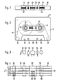
- a tape cassette 10 shown in FIGS. 1 and 2 has a cassette housing 12 of standardized type and size with two bobbindles 14 and 16 lying parallel to one another and axially parallel for a tape 18 attached to it with its ends.
- the tape reels are designed with an internal score 20 and 22, respectively, via which the tape runs at high speed alternately from one reel to the other reel with the aid of the drive hubs of the cassette drive.
- the audio tape 18 is guided along the end wall 28 of the cassette via deflecting means 24 and 26 which may be rotatably arranged in the cassette housing.
- the cassette housing 12 has through-openings 30 and 32 which are axially parallel to the reels and which receive a sound shaft which can be driven by a motor of the cassette drive when the cassette is inserted.
- pins which may be present and which protrude from the upper side of the cassette drive as tape guide means, pass through to the sound wave openings 30 and 32 with axially parallel through openings 34 and 36.
- a central opening 40 for the entry of a sound head, which is present for normal operation of the cassette drive, in particular a combined recording / playback head.
- the openings 40 to 44 in the cassette end wall 28 are each approximately the same size.
- openings 46 and 48 are cut out, which in known cassette drives accommodate, for example, a separate recording head or a tape guide element and are also referred to as reference holes.
- FIG. 3 shows schematically how the sound heads and rubber pressure rollers can be arranged next to one another in a drive provided in the device combination according to the invention with reference to the cutouts in the cassette end face 28 of an inserted cassette tape 10.
- a combination head 50 can be brought through the cassette recess 40 to the tape 18 for the usual recording and playback operation with known adjusting means.
- An erase head 52 for the recording tracks can enter the recess 42 in the cassette end wall 28.
- the magnetic heads 56 and 58 additionally present according to the invention are arranged on both sides of the combination head 50, the magnetic head 56 with a read / write system 76 through the reference opening 48, and the magnetic head 58 with an erasing system 78 through the reference opening 46 in the cassette end wall 28 Tape 18 can be moved in order to record, listen to or delete traffic information depending on the operating state.
- a rubber pressure roller for the audio shaft drive can preferably be controlled electromechanically in a cassette drive used according to the invention and, like the erasing head 52, can be moved towards the audio tape 18 through the window 42 of the cassette end face 28 in order to press it onto the audio shaft of the audio shaft drive for the drive.
- FIG. 4 shows an enlarged section of a cassette tape 18 with an arrangement of the recording tracks which is usual for stereo recordings.
- the recording of a stereo recording separated by channels R, L, which can be listened to in the direction of arrow I when the tape is in operation, is arranged on the lower half of the tape, while the upper half of the tape carries a corresponding recording with the stereo tracks RII and LII.
- a blank space 70 between the recordings on the upper and lower half of the tape forms the so-called turf, which is essential for the invention.
- traffic information with an announcement identifier is automatically recorded, which can then be deleted again with the aid of the delete system 78 of the magnetic head 58, without having to record or delete the upper and lower ones Half of the tape to impair existing stereo recordings.
- the systems 76 and 78 of the magnetic heads 56 and 58 present according to the invention are directly assigned to the lawn.
- the combination head 50 and the erasing head 52 are known heads, the combination head 50 in the embodiment shown having, for example, two magnet systems 80, 82 assigned to the two parallel tracks of a band half.
- the height of the housing of all magnetic heads used is preferably greater than the slurry te of the tape 18 selected so that the end face of the heads brought into contact with the tape acts advantageously as a tape guide.
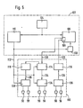
- FIG. 5 shows a block diagram of a recorder 100 which is connected to a traffic radio receiver 102 and receives the switching commands from it.
- the traffic radio receiver 102 contains a known HF / IF part 104 and an equally known NF part 106 with a tape connection 108.
- the NF signals at the output of the demodulator in the HF / IF part 104 are also known in the traffic radio receiver Traffic radio decoder 110 supplied and evaluated there as usual.
- the switching commands of the traffic radio decoder 110 are supplied to the recorder 100 via the command line 112, while the recording circuits 114 and playback circuits 116, which are constructed and switchable in a conventional manner, are, as usual, connected to the audio tape connector 108 of the traffic radio receiver via connecting lines 120, 122.
- the recorder comprises a quenching oscillator 118 which is known per se and which can be switched arbitrarily or automatically by the recording circuit.
- the recording circuit 114 and the playback circuit 116 also include the usual switches for arbitrarily switching on and off and for driving the drive. These usual switches can also be controlled in the receiving circuit 114 in the exemplary embodiment of the invention shown here via the command line 112.
- the output of the write amplifier in the recording circuit 114 is connected via a line 124 to a controllable changeover switch 134, to the control input of which the command line 112 is connected.
- the input of the sense amplifier in the playback circuit 116 is connected via the line 126 to a manually controllable changeover switch 136.
- the output of the quenching oscillator 118 is connected via a line 128 to a controllable changeover switch 138, the control input of which is also connected to the command line 112.
- a mute switch 130 for the LF part 106 of the traffic radio receiver 102 is also connected to the command line 112.
- the first connection of the switch 134 is connected to the write winding of the combination head 50, the second connection to the write winding of the magnetic head 56.
- the first connection of the switch 136 is connected to the read winding of the combination head 50, the second connection to the read winding of the magnetic head 56.
- the first connection of the switch 138 is connected to the erase head 52, the second connection to the magnetic head 58.
- the changeover switches 134, 136 connect the windings of the combination head 50 to the respective amplifiers 114, 116 and the changeover switch 138 connect the erase head 52 to the erase oscillator 118.
- a switch command is issued via the command line 112 the switches 134, 138 are given. In known traffic radio receivers, this switching command is fed only to the mute switch 130, which there causes the muting of the LF part 106 to be canceled.
- This switching command which is generated in a manner known per se, on the command line 112 causes the switches 134 and 130 to be switched over as soon as an announcement identifier is sent by the traffic radio station in addition to the normal LF signals.
- the recording circuit 114 is turned on via the command line 112. The traffic announcement transmitted by the transmitter is thus forcibly recorded on the lawn of the tape and an approximately previously recorded traffic announcement is deleted.
- the switch 136 must also be switched.
Landscapes
- Engineering & Computer Science (AREA)
- Multimedia (AREA)
- Signal Processing (AREA)
- Physics & Mathematics (AREA)
- General Physics & Mathematics (AREA)
- Recording Or Reproducing By Magnetic Means (AREA)
- Circuits Of Receivers In General (AREA)
- Input Circuits Of Receivers And Coupling Of Receivers And Audio Equipment (AREA)
Abstract
Description
Die Erfindung bezieht sich auf ein Aufnahme-IWiedergabegerät nach dem Oberbegriff des Anspruches 1.The invention relates to a recording and playback device according to the preamble of
Ein wichtiges Mittel zur Information der Verkehrsteilnehmer über die Verkehrslage und evtl. Verkehrsstörungen sind die von verschiedenen Rundfunksendern überregional und regional ausgestrahlten Verkehrsnachrichten, die ein Kraftfahrer in seinem Autoradio empfangen kann.An important means of informing road users about the traffic situation and any traffic disruptions are the national and regional traffic news broadcast by various radio stations that a driver can receive in his car radio.
Die für die regionale Rundfunkversorgung besonders geeigneten UKW-Sender, die regelmäßig Verkehrsinformationen übertragen, strahlen ständig eine für das gesamte Sendernetz übereinstimmende Senderkennung und daneben eine regional unterschiedliche Bereichskennung aus. Eine ebenfalls für das gesamte Sendernetz übereinstimmende Durchsagekennung wird nur während der Dauer einer Verkehrsdurchsage ausgestrahlt. In einem langjährig erprobten Verkehrsfunksystem werden Kennfrequenzen benutzt, die sämtlich durch Frequenzvervielfachung bzw. Frequenzteilung von der an allen UKW-Sendern als Pilotton für Stereosendungen zur Verfügung stehenden 19-kHz-Frequenz abgeleitet sind.The VHF transmitters, which are particularly suitable for regional broadcasting and which regularly transmit traffic information, continuously emit a transmitter identifier that matches the entire transmitter network and also a regionally different area identifier. An announcement identifier, which also corresponds to the entire transmitter network, is only broadcast during the duration of a traffic announcement. In a traffic radio system that has been tried and tested over many years, characteristic frequencies are used, all of which are derived by frequency multiplication or frequency division from the 19 kHz frequency available on all FM transmitters as a pilot tone for stereo broadcasts.
Überregionale Verkehrsnachrichten werden daneben noch heute über im Mittel- und Langwellenbereich arbeitende Sender mit AmplitudenModulation (AM) ausgestrahlt. Bei AM-Sendern wird als Kennung vor und nach der Sendung einer Verkehrsnachricht ein bestimmtes Ton-Signal unterschiedlicher Dauer ausgestrahlt, um Beginn und Ende der Verkehrsdurchsage zu kennzeichnen.National traffic announcements are still broadcast today via transmitters with amplitude modulation (AM) working in the medium and long-wave range. In the case of AM transmitters, a specific sound signal of different duration is broadcast as an identifier before and after the transmission of a traffic message in order to mark the beginning and end of the traffic announcement.
Elektronisch auswertbare Kennungen von Verkehrsnachrichten sind auch eine notwendige Voraussetzung für das automatische Aufzeichnen von Verkehrsdurchsagen und die dadurch erweiterten Informationsmöglichkeiten für Kraftfahrer.Electronically evaluable identifications of traffic messages are also a necessary prerequisite for the automatic recording of traffic announcements and the resulting expanded information options for drivers.
Einrichtungen zum automatischen Aufzeichnen von Verkehrsnachrichten sind beispielsweise als sogenannte Infotheken bekannt geworden, die an Autobahn-Raststätten aufgestellt werden und an welchen die Kraftfahrer automatisch aufgezeichnete Verkehrsdurchsagen abhören können.Devices for automatically recording traffic messages have become known, for example, as so-called information counters, which are set up at motorway service areas and where drivers can listen to automatically recorded traffic announcements.
Um die Informationsmöglichkeiten noch weiter zu verbessern, sind auch schon Überlegungen angestellt worden (Funkschau 1978, Heft 25, S. 1263), Verkehrsmeldungen mit Hilfe von Recordern in Verbindung mit sogenannten Verkehrsfunkempfängern, das sind Rundfunkempfänger, insbesondere Autoradios, mit einem eingebauten Verkehrsfunkdecoder, automatisch aufzuzeichnen, wobei die Durchsagekennung über eine Logikschaltung den Motor des Cassettenlaufwerks steuert.In order to further improve the information options, considerations have already been made (Funkschau 1978, number 25, p. 1263), traffic reports using recorders in conjunction with so-called traffic radio receivers, i.e. radio receivers, in particular car radios, with a built-in traffic radio decoder, automatically to record, the announcement identifier controls the motor of the cassette drive via a logic circuit.
Zur Vorbereitung einer Aufnahme ist es hierbei notwendig, in den Recorder eine Leercassette einzulegen und den Recorder in Aufnahmebereitschaft zu bringen. Der Motor des Cassettenlaufwerks erhält dann während der Dauer der Durchsagekennung, d. h. während einer Verkehrsdurchsage, über die Logikschaltung Spannung und bleibt am Ende der Ausstrahlung der Durchsagekennung wieder stehen. Ferner wird mit Hilfe der Durchsagekennung ein Flip-Flop gesetzt, das eine Anzeige auslöst, die über das Flip-Flop auch nach Beendigung der Verkehrsmeldung erhalten bleibt. Diese Anzeige macht den Kraftfahrer darauf aufmerksam, daß während seiner Abwesenheit eine Verkehrsmeldung aufgenommen worden ist, die er dann beliebig oft abhören kann.To prepare for a recording, it is necessary to insert an empty cassette into the recorder and to put the recorder on standby. The motor of the cassette drive then receives during the duration of the announcement identification, i. H. during a traffic announcement, via the logic circuit voltage and stops again at the end of the broadcasting of the announcement identifier. Furthermore, a flip-flop is set with the aid of the announcement identifier, which triggers a display which is retained via the flip-flop even after the traffic announcement has ended. This display alerts the driver that a traffic announcement has been recorded during his absence, which he can then listen to as often as he wishes.
Der geräteseitige Aufwand für die Logikschaltung dieses mit einem üblichen Cassettenrecorder ausführbaren Vorschlages ist zwar verhältnismäßig gering, erfordert aber die Verwendung einer Leercassette zum Aufzeichnen der. Verkehrsmeldungen. Diese Notwendigkeit ist deshalb nachteilig, weil sie das Abhören von Musikcassetten verhindert, wenn Verkehrsmeldungen aufgezeichnet werden sollen, damit man eine beispielsweise wegen einer kritischen Verkehrssituation nicht genau verstandene Meldung wiederholen lassen kann.The expenditure on the device for the logic circuitry of this proposal, which can be carried out with a conventional cassette recorder, is relatively low, but requires the use of an empty cassette for recording the. Traffic-news. This necessity is disadvantageous because it prevents listening to music tapes when traffic reports are to be recorded, so that a message that is not exactly understood, for example due to a critical traffic situation, can be repeated.
Die Einrichtung gemäß der vorliegenden Erfindung gestattet es, eintreffen Verkehrsmeldungen zu jedem Zeitpunkt und bei jedem Betriebszustand auch auf bespielte Musikcassetten speichern zu können, ohne die vorhandene Aufzeichnung zu beeinträchtigen.The device according to the present invention makes it possible to be able to store incoming traffic reports at any time and in any operating state, even on recorded music cassettes, without impairing the existing recording.
Diese Aufgabe wird durch die im Kennzeichen des Anspruchs 1 angegebenen Merkmale gelöst.This object is achieved by the features specified in the characterizing part of
Vorteilhafte Ausgestaltungen und Weiterbildungen der Erfindung sind in den Unteransprüchen angegeben.Advantageous refinements and developments of the invention are specified in the subclaims.
Es ist an sich bekannt, (GB-A-1 512192) in dem Zwischenraum' zwischen den beiden Nutzsignalspuren einer Kassette zugleich mit dem Nutzsignal auch Kontrollsignale aufzuzeichnen, unter anderem, um das spätere Wiederauffinden bestimmter Bandstellen zu erleichtern. Dazu sind die Magnetköpfe für das Nutzsignal und das Kontrollsignal in einem Gehäuse vereinigt und werden auch gleichzeitig zum Schreiben der Nutz- und Kontrollsignale bzw. zum Lesen aufgezeichneter Signale eingeschaltet.It is known per se (GB-A-1 512192) to record control signals in the space between the two useful signal tracks of a cassette at the same time as the useful signal, in order, among other things, to make it easier to find certain tape locations again later. For this purpose, the magnetic heads for the useful signal and the control signal are combined in a housing and are simultaneously switched on for writing the useful and control signals or for reading recorded signals.
Die Erfindung zeichnet sich demgegenüber dadurch aus, daß ein gleichzeitiges Abhören des Nutzsignals und eine Aufzeichnung einer Verkehrsinformation möglich ist, ohne die bestehende Musikaufzeichnung zu beeinträchtigen.In contrast, the invention is characterized in that simultaneous listening to the useful signal and recording of traffic information is possible without impairing the existing music recording.
Die Tonköpfe heute üblicher Cassettenlaufwerke sind so bemessen, daß beim Bespielen von Leercassetten zwischen den Aufzeichnungsspuren auf der oberen und unteren Bandhälfte ein Rasen frei bleibt, dessen minimale Breite durch Normvorschriften auf 480 ...,m festgelegt ist. Bei kommerziell bespielten Musikcassetten liegt die Rasenbreite sogar bei 560 wm.The tape heads of today's conventional cassette drives are dimensioned so that when recording empty cassettes between the recording tracks on the upper and lower half of the tape, a lawn remains free, the minimum width of which is fixed at 480 ..., m by standard regulations. In the case of commercially recorded music cassettes, the lawn width is even 560 wm.
Bei diesen festliegenden Rasenbreiten gewährleistet eine im Bereich zwischen etwa 150 und 200 I-Lm liegende Spurbreite einer erfindungsgemäßen Aufzeichnung von Verkehrsdurchsagen einen ausreichenden Störabstand zu den benachbarten Aufzeichnungsspuren der oberen und unteren Bandhälfte. Diese Spurbreite kann ohne weiteres eingehalten werden, wenn als zusätzlicher Aufnahme/Wiedergabekopf für das Aufzeichnen und Abhören von Verkehrsdurchsagen ein sogenannter Videokopf eingesetzt wird, wie er als rotierender Magnetkopf in Videoaufzeichnungsgeräten schon in Ausführungen bekannt ist, die eine einwandfreie Aufzeichnung und Abtastung von Spurbreiten von weniger als 100 µm ermöglichen.With these fixed lawn widths one guarantees in the range between about 150 and 200 I-Lm track width of a recording of traffic announcements according to the invention a sufficient signal-to-noise ratio to the adjacent recording tracks of the upper and lower half of the tape. This track width can easily be maintained if, as an additional recording / playback head for recording and listening to traffic announcements, a so-called video head is used, as is already known in versions as a rotating magnetic head in video recorders, which flawlessly records and scans track widths of less than 100 µm.
Die Verwendung eines solchen Magnetkopfes als Aufnahme/Wiedergabekopf und eines entsprechend dimensionierten Elektromagneten als Löschkopf gestattet also in einer erfindungsgemäßen Einrichtung die Einhaltung eines genügenden Störabstandes einer Aufzeichnung auf dem Rasen des Tonbandes ohne Übersprechen auf die benachbarten Tonspuren bei der Aufnahme und ohne Beeinträchtigung einer Aufzeichnung in den benachbarten Tonspuren beim Löschen einer auf den Rasen des Tonbandes aufgezeichneten Verkehrsdurchsage.The use of such a magnetic head as a recording / playback head and a correspondingly dimensioned electromagnet as an erasing head thus allows in a device according to the invention to maintain a sufficient signal-to-noise ratio for recording on the lawn of the tape without crosstalk to the adjacent sound tracks when recording and without impairing a recording in the adjacent audio tracks when deleting a traffic announcement recorded on the lawn of the tape.
Die am häufigsten eingesetzten, weltweit eingeführten Tonbandcassetten besitzen ein Cassettengehäuse genormter Bauart und Größe mit zwei achsparallel nebeneinander liegenden Bandspulen für das in dem Cassettengehäuse über Umlenkmittel zwischen den Bandspulen entlang der Cassettenstirnwand eingeführte Tonband, wobei in der Mitte der Cassettenstirnwand eine Öffnung für den Eintritt des für Normalbetrieb des Cassettenlaufwerks benutzten Tonkopfes und zwei spiegelsymmetrisch von der etwa gleich großen Mittelöffnung entfernt liegende Öffnungen für den Eintritt einer zum jeweiligen Tonwellenantrieb gehörenden Gummiandruckrolle und/oder eines Löschkopfes vorhanden sind. Zwischen dieser Mittelöffnung und den seitlichen Öffnungen sind in der Cassettenstirnwand zwei weitere, etwas kleinere Öffnungen ausgespart, die bei bekannten Geräten den Eintritt einer Bandführung und/oder eines zusätzlichen Tonkopfes ermöglichen, sogenannte Referenzlöcher. Ferner weisen diese auch als CC-Cassetten bekannten Tonbandcassetten zu den Bandspulen achsparallele Tonwellen-Durchgangsöffnungen auf, die mit gleichen Abständen von den Seitenwänden und der Stirnwand des Cassettengehäuses jeweils im Bereich der Öffnungen für den Eintritt der Gummiandruckrolle angeordnet sind.The most commonly used, worldwide introduced tape cassettes have a cassette housing of standardized type and size with two reels lying parallel to one another parallel to the axis for the tape introduced into the cassette housing via deflection means between the reels along the end wall of the cassette, with an opening in the middle of the end wall for the cassette Normal operation of the cassette drive used sound head and two mirror-symmetrical openings from the approximately equal central opening for the entry of a rubber pressure roller belonging to the respective sound shaft drive and / or an erasing head are present. Between this central opening and the side openings, two further, somewhat smaller openings are left in the cassette end wall, which allow known tape devices and tape heads and / or an additional sound head to enter, so-called reference holes. Furthermore, these cassette tapes, also known as CC cassettes, have axially parallel sound-wave through-openings to the reels, which are arranged at equal distances from the side walls and the end wall of the cassette housing in the region of the openings for the entry of the rubber pressure roller.
Bei den Autoreverse-Laufwerken sind die beiden außen liegenden Öffnungen in der Stirnwand der Cassette durch die Gummiandruckrolle für die beiden Tonwellenantriebe besetzt. Es ist auch schon ein Autoreverse-Laufwerk bekannt, bei dem ein für den Normalbetrieb vorgesehener Löschkopf neben der Gummiandruckrolle angeordnet ist, und durch die gleiche Öffnung der Cassette mit dem Band in Berührung gebracht werden kann.In the Autoreverse drives, the two outer openings in the front wall of the cassette are occupied by the rubber pressure roller for the two shaft drives. An autoreverse drive is also known, in which an erase head intended for normal operation is arranged next to the rubber pressure roller and can be brought into contact with the tape through the same opening of the cassette.
Bei einer bevorzugten Auführungsform der erfindungsgemäßen Einrichtung sind deshalb die zusätzlichen Magnetköpfe für die Aufnahme und Wiedergabe bzw. für die Löschung einer Verkehrsdurchsage auf dem Rasen des Cassettentonbandes vorzugsweise so auf Kopfträgern des Cassettenlaufwerks angeordnet, daß sie durch die sog. Referenzlöcher zwischen der Mittelöffnung und den außen liegenden Öffnungen in der Cassettenstirnwand an das Tonband einer eingelegten Cassette herangeführt werden können.In a preferred embodiment of the device according to the invention, the additional magnetic heads for recording and playback or for deleting a traffic announcement on the lawn of the cassette tape are preferably arranged on head carriers of the cassette drive in such a way that they pass through the so-called reference holes between the central opening and the outside openings in the front of the cassette can be brought up to the tape of an inserted cassette.
Bei einer besonders vorteilhaften Ausgestaltung der zusätzlichen Magnetköpfe sind deren Gehäuse gleichzeitig als Bandführungen ausgebildet, die mit gerätefesten Bandführungen des Cassettenlaufwerks, die in entsprechenden Öffnungen einer eingelegten Cassette eintreten, zusammenwirken und für die gewünschte Führung bzw. Umlenkung des an den Antriebsorganen und den Köpfen vorbeilaufenden Bandes sorgen.In a particularly advantageous embodiment of the additional magnetic heads, their housings are designed at the same time as tape guides, which interact with device-fixed tape guides of the cassette drive, which enter the corresponding openings of an inserted cassette, and for the desired guidance or deflection of the tape passing the drive elements and the heads to care.
Die Funktion des erfindungsgemäßen Systems setzt lediglich voraus, daß eine Cassette in das Laufwerk der erfindungsgemäßen Einrichtung eingelegt ist und hat den Vorteil, daß unter dieser einfachen Bedingung grundsätzlich alle eintreffenden Verkehrsnachrichten auf dem Rasen des Tonbandes abgespeichert werden können.The function of the system according to the invention only presupposes that a cassette is inserted in the drive of the device according to the invention and has the advantage that, under this simple condition, basically all incoming traffic messages can be stored on the lawn of the tape.
Wenn gerade eine Cassette gehört wird, wird beim Empfang einer Durchsagekennung im Verkehrsfunkempfänger dessen Tonbandgeräteanschluß mit der Aufnahmeelektronik und diese mit dem zusätzlichen Aufnahmekopf verbunden.If a cassette is being heard, when an announcement identifier is received in the traffic radio receiver, its tape recorder connection is connected to the recording electronics and the latter to the additional recording head.
Das erfindungsgemäße System hat also den Vorteil einer einwandfreien Information des Kraftfahrers auch in schwierigen Verkehrssituationen, in denen sich der Kraftfahrer nicht auf die Originaldurchsage der Nachricht konzentrieren kann.The system according to the invention therefore has the advantage of providing the driver with correct information even in difficult traffic situations in which the driver cannot concentrate on the original announcement of the message.
Die Benutzung des Rasens zwischen den Aufzeichnungsspuren des Tonbandes reicht dabei trotz der geringen Spurbreite in jedem Fall für eine einwandfreie Unterrichtung des Kraftfahrers aus, da für derartige Durchsagen Telefonqualität ausreicht.The use of the lawn between the recording tracks of the tape is sufficient in any case for the driver to be properly informed, despite the small track width, since telephone quality is sufficient for such announcements.
Die automatische Steuerung der erfindungsgemäßen Einrichtung erfolgt mit Hilfe einer Logikschaltung, die bei einer bevorzugten Ausführungsform Teil eines Mikroprozessors sein kann. Als Steuersignale dienen dabei die mit einer Verkehrsnachricht empfangene und aufgezeichnete Durchsagekennung sowie weitere bei der beispielsweise über Drucktasten durchgeführten Bedienung des Gerätes auftretende Signale.The automatic control of the device according to the invention takes place with the aid of a logic circuit, which in a preferred embodiment can be part of a microprocessor. The control signals are the announcement identifier received and recorded with a traffic message, as well as further signals which occur when the device is operated, for example, using pushbuttons.
Weitere Vorzüge und Merkmale der Erfindung ergeben sich aus der nachfolgenden Beschreibung und der Zeichnung eines bevorzugten Ausführungsbeispiels der Erfindung. Es zeigen :
Figuren 1 und 2 eine stirnseitige Ansicht und eine Draufsicht einer handelsüblichen Tonbandcassette, wie sie bei der Erfindung vorzugsweise verwendet werden soll,- Figur 3 eine schematisch stark vereinfachte Darstellung einer Anordnung der Tonköpfe und Gummiandruckrollen in einem Autoreverse-Laufwerk zur Veranschaulichung der Zuordnung zu den stirnseitigen Öffnungen einer Tonbandcassette gemäß Fig. 1 und 2,
- Figur 4 in vergrößertem Maßstab eine schematisch stark vereinfachte Darstellung eines Abschnittes des Cassettentonbandes zur Veranschaulichung der Zuordnung der Tonköpfe eines erfindungsgemäß ausgerüsteten Laufwerkes zu den in üblicher Weise auf dem Band zugeordneten Aufzeichnungsspuren, und
- Figur 5 ein Blockschaltbild eines erfindungsgemäßen Recorders.
- FIGS. 1 and 2 show an end view and a top view of a commercially available cassette tape, as is preferably to be used in the invention,
- Figure 3 is a schematic, greatly simplified representation of an arrangement of the heads and Rubber pressure rollers in an autoreverse drive to illustrate the assignment to the front openings of a tape cassette according to FIGS. 1 and 2,
- 4 shows, on an enlarged scale, a schematically, greatly simplified representation of a section of the cassette tape to illustrate the assignment of the sound heads of a drive equipped according to the invention to the recording tracks assigned to the tape in the usual manner, and
- Figure 5 is a block diagram of a recorder according to the invention.
Eine in Figuren 1 und 2 gezeigte Tonbandcassette 10 besitzt ein Cassettengehäuse 12 genormter Bauart und Größe mit zwei achsparallel nebeneinander liegenden Banspulen 14 und 16 für ein daran mit seinen Enden befestigtes Tonband 18. Die Bandspulen sind mit einem Innenritzei 20 bzw. 22 ausgebildet, über welche das Tonband bei Schnellauf mit Hilfe von Antriebsnaben des Cassettenlaufwerks wechselseitig von einer Bandspule zur anderen Bandspule läuft. Zwischen den auf den Bandspulen 14 und 16 sitzenden Bandwickeln ist das Tonband 18 über ggf. drehbar im Cassettengehäuse angeordnete Umlenkmittel 24 und 26 entlang der Stirnwand 28 der Cassette geführt.A
Hinter dem entlang der Cassettenstirnwand geführten Tonband besitzt das Cassettengehäuse 12 zu den Bandspulen achsparallele Durchgangsöffnungen 30 und 32, welche beim Einlegen der Cassette eine von einem Motor des Cassettenlaufwerks antreibbare Tonwelle aufnehmen. Zu den Tonwellen-Öffnungen 30 und 32 achsparallele Durchgangsöffnungen 34 und 36 nehmen bei eingelegter Cassette ggf. vorhandene Stifte auf, die als Bandführungsmittel von der Oberseite des Cassettenlaufwerks vorstehen.Behind the tape which is guided along the end wall of the cassette, the
In der Cassettenstirnwand 28, siehe Figur 1, ist eine Mittelöffnung 40 für den Eintritt eines für Normalbetrieb des Cassettenlaufwerks vorhandenen Tonkopfes, insbesondere eines kombinierten Aufnahme/Wiedergabekopfes, ausgespart. Spiegelsymmetrisch zu beiden Seiten dieser Mittelöffnung 40 angeordnete Aussparungen 42 und 44 in der Cassettenstirnwand dienen zum Eintritt einer Gummiandruckrolle eines für den Bandantrieb vorhandenen Tonwellenantriebes.In the
Die Öffnungen 40 bis 44 in der Cassettenstirnwand 28 sind jeweils etwa gleich groß.The
Zwischen der Mittelöffnung 40 und den seitlich davon liegenden Öffnungen 42 und 44 sind jeweils etwas kleinere Öffnungen 46 bzw. 48 ausgespart, welche bei bekannten Cassettenlaufwerken beispielsweise einen gesondenen Aufnahmekopf oder ein Bandführungselement aufnehmen und auch als Referenzlöcher bezeichnet werden.Between the
Figur 3 zeigt schematisch, wie die bei einem in der erfindungsgemäßen Gerätekombination vorgesehenen Laufwerk die Tonköpfe und Gummiandruckrollen mit Bezug auf die in der Cassettenstirnseite 28 vorhandenen Aussparungen einer eingelegten Tonbandcassette 10 nebeneinander angeordnet sein können. Ein Kombinationskopf 50 kann dabei für den üblichen Aufnahme- und Wiedergabebetrieb mit an sich bekannten Stellmitteln durch die Cassettenaussparung 40 an das Tonband 18 herangeführt werden.FIG. 3 shows schematically how the sound heads and rubber pressure rollers can be arranged next to one another in a drive provided in the device combination according to the invention with reference to the cutouts in the
Ein Löschkopf 52 für die Aufzeichnungsspuren kann in die Aussparung 42 in der Cassettenstirnwand 28 eintreten. Die erfindungsgemäß zusätzlich vorhandenen Magnetköpfe 56 und 58 sind zu beiden Seiten des Kombinationskopfes 50 angeordnet, wobei der Magnetkopf 56 mit einem Schreib/Lesesystem 76 durch die Referenzöffnung 48, und der Magnetkopf 58 mit einem Löschsystem 78 durch die Referenzöffnung 46 in der Cassettenstirnwand 28 an das Tonband 18 heranbewegt werden kann, um je nach Betriebszustand eine Verkehrsinformation aufzuzeichnen, abzühören oder zu löschen.An
Eine mit 60 angedeutete Gummiandruckrolle für den Tonwellenantrieb ist bei einem erfindungsgemäß eingesetzten Cassettenlaufwerk vorzugsweise elektromechanisch steuerbar und kann wie der Löschkopf 52 durch das Fenster 42 der Cassettenstirnseite 28 an das Tonband 18 heranbewegt werden, um dieses für den Antrieb an die Tonwelle des Tonwellenantriebes anzupressen.A rubber pressure roller for the audio shaft drive, indicated by 60, can preferably be controlled electromechanically in a cassette drive used according to the invention and, like the erasing
Figur 4 zeigt einen vergrößert dargestellten Teilabschnitt eines Cassettentonbandes 18 mit einer für Stereoaufzeichnungen üblichen Anordnung der Aufzeichnungsspuren. Dabei ist die nach Kanälen R, L getrennte Aufzeichnung einer Stereoaufnahme, die bei Betrieb des Bandes in Richtung des Pfeiles I abgehört werden kann, auf der unteren Bandhälfte angeordnet, während die obere Bandhälfte eine entsprechende Aufzeichnung mit den Stereospuren RII und LII trägt. Ein zwischen den Aufzeichnungen auf der oberen und unteren Bandhälfte vorhandener, unbespielter Zwischenraum 70 bildet den sogenannten Rasen, der für die Erfindung wesentlich ist. Auf diesem Rasen wird gemäß der Erfindung mit Hilfe des Schreib/Lesesystems 76 des Magnetkopfes 56 eine Verkehrsinformation mit Durchsagekennung automatisch aufgezeichnet, die dann mit Hilfe des Löschsystems 78 des Magnetkopfes 58 wieder gelöscht werden kann, ohne beim Aufnehmen oder Löschen die auf der oberen und unteren Bandhälfte vorhandenen Stereoaufzeichnungen zu beeinträchtigen.FIG. 4 shows an enlarged section of a
Zu diesem Zweck sind die Systeme 76 und 78 der erfindungsgemäß vorhandenen Magnetköpfe 56 und 58, deren Spalthöhe etwas kleiner gewählt ist als die genormte Breite des Rasens, unmittelbar dem Rasen zugeordnet.For this purpose, the
Bei dem Kombinationskopf 50 und dem Löschkopf 52 handelt es sich um bekannte köpfe, wobei der Kombinationskopf 50 bei der gezeigten Ausführungsform beispielsweise zwei den beiden Parallelspuren einer Bandhälfte zugeordnete Magnetsysteme 80, 82 besitzt.The
Die Höhe der Gehäuse aller verwendeten Magnetköpfe ist vorzugsweise größer als die Breite des Tonbandes 18 gewählt, so daß die Stirnseite der mit dem Band in Berührung gebrachten Köpfe in vorteilhafter Weise als Bandführung wirkt.The height of the housing of all magnetic heads used is preferably greater than the slurry te of the
Figur 5 zeigt ein Blockschaltbild eines Recorders 100, der mit einem Verkehrsfunkempfänger 102 verbunden ist und von diesem die Schaltbefehle erhält.FIG. 5 shows a block diagram of a
Der Verkehrsfunkempfänger 102 enthält ein an sich bekanntes HF/ZF-Teil 104 und ein ebenso bekanntes NF-Teil 106 mit einem Tonbandanschluß 108. Die NF-Signale am Ausgang des Demodulators im HF/ZF-Teil 104 werden in bekannter Weise im Verkehrsfunkempfänger auch einem Verkehrsfunkdecorder 110 zugeführt und dort wie üblich ausgewertet.The
Über die Befehlsleitung 112 werden dem Recorder 100 die Schaltbefehle des Verkehrsfunkdecoders 110 zugeleitet, während die in an sich bekannter Technik aufgebauten und schaltbaren Aufnahmeschaltungen 114 und Wiedergabeschaltungen 116 wie üblich über Verbindungsleitungen 120, 122 mit dem Tonbandanschluß 108 des Verkehrsfunkempfängers verbunden sind. Außerdem umfaßt der Recorder einen an sich bekannten Löschoszillator 118, der willkürlich bzw. automatisch von der Aufnahmeschaltung her schaltbar ist.The switching commands of the
Die Aufnahmeschaltung 114 und die Wiedergabeschaltung 116 umfassen auch die üblichen Schalter zum willkürlichen Ein- und Ausschalten und für den Antrieb des Laufwerks. Diese üblichen Schalter sind in der Aufnahmeschaltung 114 bei dem hier dargestellten Ausführungsbeispiel der Erfindung zusätzlich über die Befehlsleitung 112 steuerbar.The recording circuit 114 and the
Der Ausgang des Schreibverstärkers in der Aufnahmeschaltung 114 ist über eine Leitung 124 mit einem steuerbaren Umschalter 134 verbunden, an dessen Steuereingang die Befehlsleitung 112 angeschlossen ist. Der Eingang des Leseverstärkers in der Wiedergabeschaltung 116 ist über die Leitung 126 mit einem von Hand steuerbaren Umschalter 136 verbunden. Schließlich ist der Ausgang des Löschoszillators 118 über eine Leitung 128 mit einem steuerbaren Umschalter 138 verbunden, dessen Steuereingang ebenfalls an die Befehlsleitung 112 angeschlossen ist. Außerdem ist an die Befehlsleitung 112 noch ein Stummschalter 130 für den NF-Teil 106 des Verkehrsfunkempfängers 102 angeschlossen.The output of the write amplifier in the recording circuit 114 is connected via a
Der erste Anschluß des Umschalters 134 ist mit der Schreibwicklung des Kombinationskopfes 50, der zweite Anschluß mit der Schreibwicklung des Magnetkopfes 56 verbunden. Der erste Anschluß des Umschalters 136 ist mit der Lesewicklung des Kombinationskopfes 50, der zweite Anschluß mit der Lesewicklung des Magnetkopfes 56 verbunden. Der erste Anschluß des Umschalters 138 ist mit dem Löschkopf 52, der zweite Anschluß mit dem Magnetkopf 58 verbunden.The first connection of the
In der normalen Stellung verbinden die Umschalter 134, 136 die Wicklungen des Kombinationskopfes 50 mit den jeweiligen Verstärkern 114, 116 und der Umschalter 138 den Löschkopf 52 mit dem Löschoszillator 118. Sobald der Verkehrsfunkdecoder 110 eine Durchsagekennung ermittelt, wird über die Befehlsleitung 112 ein Schaltbefehl an die Umschalter 134, 138 gegeben. In bekannten Verkehrsfunkempfängern wird dieser Schaltbefehl allein dem Stummschalter 130 zugeführt, der dort eine Aufhebung der Stummschaltung des NF-Teils 106 bewirkt.In the normal position, the changeover switches 134, 136 connect the windings of the
Dieser in an sich bekannter Weise erzeugte Schaltbefehl auf der Befehlsleitung 112 bewirkt eine Umschaltung der Umschalter 134 und 130, sobald zusätzlich zu den normalen NF-Signalen noch eine Durchsagekennung vom Verkehrsfunksender gesendet wird. Außerdem wird über die Befehlsleitung 112 die Aufzeichnungsschaltung 114 eingeschaltet. Damit wird die vom Sender durchgegebene Verkehrsmeldung zwangsweise auf dem Rasen des Tonbandes aufgezeichnet und eine etwa zuvor aufgezeichnete Verkehrsmeldung gelöscht.This switching command, which is generated in a manner known per se, on the
Soll die so aufgezeichnete Verkehrsmeldung abgehört werden, dann ist neben der in üblicher Weise einzuschaltenden Wiedergabeschaltung zusätzlich der Umschalter 136 umzuschalten.If the traffic report recorded in this way is to be listened to, then in addition to the playback circuit to be switched on in the usual way, the
Claims (4)
Priority Applications (1)
| Application Number | Priority Date | Filing Date | Title |
|---|---|---|---|
| AT81109518T ATE15730T1 (en) | 1980-12-02 | 1981-11-05 | DEVICE FOR STORING AND LISTENING TO TRAFFIC ANNOUNCEMENTS. |
Applications Claiming Priority (2)
| Application Number | Priority Date | Filing Date | Title |
|---|---|---|---|
| DE19803045380 DE3045380A1 (en) | 1980-12-02 | 1980-12-02 | METHOD AND DEVICE FOR STORING AND LISTENING TO TRAFFIC INFORMATION |
| DE3045380 | 1980-12-02 |
Publications (2)
| Publication Number | Publication Date |
|---|---|
| EP0053734A1 EP0053734A1 (en) | 1982-06-16 |
| EP0053734B1 true EP0053734B1 (en) | 1985-09-18 |
Family
ID=6118097
Family Applications (1)
| Application Number | Title | Priority Date | Filing Date |
|---|---|---|---|
| EP81109518A Expired EP0053734B1 (en) | 1980-12-02 | 1981-11-05 | Device for the registration and playback of traffic news |
Country Status (4)
| Country | Link |
|---|---|
| EP (1) | EP0053734B1 (en) |
| JP (1) | JPS57123509A (en) |
| AT (1) | ATE15730T1 (en) |
| DE (1) | DE3045380A1 (en) |
Families Citing this family (2)
| Publication number | Priority date | Publication date | Assignee | Title |
|---|---|---|---|---|
| US4713801A (en) * | 1986-02-20 | 1987-12-15 | Hale Arthur D | Radio-tape recorder for automotive use |
| DE3833452A1 (en) * | 1988-10-01 | 1990-04-05 | Grundig Emv | METHOD FOR PREVENTING ACCIDENTAL OVERWRITING OF VIDEO SIGNAL SECTIONS RECORDED ON VIDEO MAGNETIC TAPE, AND VIDEO MAGNETIC TAPE RECORDER FOR CARRYING OUT THIS METHOD |
Family Cites Families (6)
| Publication number | Priority date | Publication date | Assignee | Title |
|---|---|---|---|---|
| DE2032185C3 (en) * | 1970-06-30 | 1978-06-15 | Blaupunkt-Werke Gmbh, 3200 Hildesheim | Device for marking, selecting and recording traffic announcements |
| JPS5219527Y2 (en) * | 1971-06-07 | 1977-05-06 | ||
| JPS5299303U (en) * | 1976-01-26 | 1977-07-27 | ||
| JPS5255608A (en) * | 1975-10-31 | 1977-05-07 | Sanyo Electric Co Ltd | Magnetic recording and playback system |
| GB1500252A (en) * | 1976-05-20 | 1978-02-08 | Matsushita Electric Ind Co Ltd | Magnetic tape and recording method therefor |
| DE2725050A1 (en) * | 1977-06-03 | 1978-12-21 | Hans Sukopp | Car radio with store - which is controlled by broadcast signals, e.g. containing traffic condition information, for selective recall |
-
1980
- 1980-12-02 DE DE19803045380 patent/DE3045380A1/en active Granted
-
1981
- 1981-11-05 EP EP81109518A patent/EP0053734B1/en not_active Expired
- 1981-11-05 AT AT81109518T patent/ATE15730T1/en not_active IP Right Cessation
- 1981-12-02 JP JP56192992A patent/JPS57123509A/en active Pending
Non-Patent Citations (1)
| Title |
|---|
| FUNKSCHAU, Band 59, 1. Dezember 1978, MÜNCHEN (DE) D. HEISS: "ARI-Infothek im Auto- eine Entwicklungsstudie" Seite 1263 * |
Also Published As
| Publication number | Publication date |
|---|---|
| ATE15730T1 (en) | 1985-10-15 |
| DE3045380A1 (en) | 1982-07-01 |
| DE3045380C2 (en) | 1989-06-22 |
| JPS57123509A (en) | 1982-08-02 |
| EP0053734A1 (en) | 1982-06-16 |
Similar Documents
| Publication | Publication Date | Title |
|---|---|---|
| EP0283708B1 (en) | Radio receiver with two traffic radio decoders | |
| DE2930509A1 (en) | TRAFFIC RADIO SYSTEM | |
| EP0065615A1 (en) | UHF receiver for a traffic information radio broadcasting system | |
| DE3121034A1 (en) | VHF RECEIVER | |
| DE4222877C2 (en) | Process for the transmission of regionally different information in single-frequency networks and receiver to carry out the measures at the receiving end | |
| EP0053734B1 (en) | Device for the registration and playback of traffic news | |
| EP0166861A2 (en) | Method for recording a television signal | |
| DE4408930A1 (en) | Combination audio system suitable for motor vehicle installation | |
| DE3912945A1 (en) | Car radio receiving traffic broadcast - uses recorded text for traffic information supplied when radio is switched off | |
| EP1219027B1 (en) | Method and device for operating an audio device in a motor vehicle | |
| DE3124858C2 (en) | Radio-cassette recorder combination | |
| DE3806972A1 (en) | Device for receiving, detecting and reproducing traffic radio announcements | |
| DE4230600C2 (en) | Radio receiver | |
| DE3028691C2 (en) | Magnetic tape recorder | |
| DE3805438A1 (en) | System for recording and reproducing video signals | |
| DE2807483A1 (en) | PROCEDURE FOR INFORMATION ABOUT ROAD AND TRAFFIC CONDITIONS AND DEVICE FOR CARRYING OUT THIS PROCEDURE | |
| EP0790719B1 (en) | Method and receiver for the reception and reproduction of digitally coded traffic messages | |
| DE3706822A1 (en) | Method for storing transmissions | |
| EP0364998B1 (en) | Recording-reproducing apparatus for the gapless recording and/or reproducing of messages | |
| DE3347231C2 (en) | ||
| DE3905122C1 (en) | ||
| DE4031431A1 (en) | Traffic information radio car receiver - switches from stereo to mono reproduction mode when traffic announcement is detected | |
| EP0961429A2 (en) | Method and means for displaying the actual function allocated to a control button in audio equipment in an automobile, such as a car radio | |
| EP0753853B1 (en) | Information processing device with remote control | |
| DE1762546C3 (en) | Inductive transmission arrangement |
Legal Events
| Date | Code | Title | Description |
|---|---|---|---|
| PUAI | Public reference made under article 153(3) epc to a published international application that has entered the european phase |
Free format text: ORIGINAL CODE: 0009012 |
|
| AK | Designated contracting states |
Designated state(s): AT CH FR GB IT |
|
| 17P | Request for examination filed |
Effective date: 19820920 |
|
| ITF | It: translation for a ep patent filed |
Owner name: STUDIO JAUMANN |
|
| GRAA | (expected) grant |
Free format text: ORIGINAL CODE: 0009210 |
|
| AK | Designated contracting states |
Designated state(s): AT CH FR GB IT LI |
|
| REF | Corresponds to: |
Ref document number: 15730 Country of ref document: AT Date of ref document: 19851015 Kind code of ref document: T |
|
| ET | Fr: translation filed | ||
| GBPC | Gb: european patent ceased through non-payment of renewal fee | ||
| PLBE | No opposition filed within time limit |
Free format text: ORIGINAL CODE: 0009261 |
|
| STAA | Information on the status of an ep patent application or granted ep patent |
Free format text: STATUS: NO OPPOSITION FILED WITHIN TIME LIMIT |
|
| 26N | No opposition filed | ||
| GBDL | Gb: delete "european patent ceased" from journal |
Free format text: 5080, PAGE 4896 |
|
| PGFP | Annual fee paid to national office [announced via postgrant information from national office to epo] |
Ref country code: AT Payment date: 19890911 Year of fee payment: 9 |
|
| PGFP | Annual fee paid to national office [announced via postgrant information from national office to epo] |
Ref country code: GB Payment date: 19891031 Year of fee payment: 9 |
|
| PGFP | Annual fee paid to national office [announced via postgrant information from national office to epo] |
Ref country code: FR Payment date: 19891129 Year of fee payment: 9 |
|
| ITTA | It: last paid annual fee | ||
| PGFP | Annual fee paid to national office [announced via postgrant information from national office to epo] |
Ref country code: CH Payment date: 19900216 Year of fee payment: 9 |
|
| PG25 | Lapsed in a contracting state [announced via postgrant information from national office to epo] |
Ref country code: GB Effective date: 19901105 Ref country code: AT Effective date: 19901105 |
|
| PG25 | Lapsed in a contracting state [announced via postgrant information from national office to epo] |
Ref country code: LI Effective date: 19901130 Ref country code: CH Effective date: 19901130 |
|
| GBPC | Gb: european patent ceased through non-payment of renewal fee | ||
| PG25 | Lapsed in a contracting state [announced via postgrant information from national office to epo] |
Ref country code: FR Effective date: 19910731 |
|
| REG | Reference to a national code |
Ref country code: CH Ref legal event code: PL |
|
| REG | Reference to a national code |
Ref country code: FR Ref legal event code: ST |