EP0053685A2 - Single use ribbon cartridge with frangible resistive element for restraining the translating take-up spool - Google Patents
Single use ribbon cartridge with frangible resistive element for restraining the translating take-up spool Download PDFInfo
- Publication number
- EP0053685A2 EP0053685A2 EP81108562A EP81108562A EP0053685A2 EP 0053685 A2 EP0053685 A2 EP 0053685A2 EP 81108562 A EP81108562 A EP 81108562A EP 81108562 A EP81108562 A EP 81108562A EP 0053685 A2 EP0053685 A2 EP 0053685A2
- Authority
- EP
- European Patent Office
- Prior art keywords
- spool
- take
- ribbon
- cartridge
- axle
- Prior art date
- Legal status (The legal status is an assumption and is not a legal conclusion. Google has not performed a legal analysis and makes no representation as to the accuracy of the status listed.)
- Granted
Links
Images

Classifications
-
- B—PERFORMING OPERATIONS; TRANSPORTING
- B41—PRINTING; LINING MACHINES; TYPEWRITERS; STAMPS
- B41J—TYPEWRITERS; SELECTIVE PRINTING MECHANISMS, i.e. MECHANISMS PRINTING OTHERWISE THAN FROM A FORME; CORRECTION OF TYPOGRAPHICAL ERRORS
- B41J32/00—Ink-ribbon cartridges
-
- B—PERFORMING OPERATIONS; TRANSPORTING
- B41—PRINTING; LINING MACHINES; TYPEWRITERS; STAMPS
- B41J—TYPEWRITERS; SELECTIVE PRINTING MECHANISMS, i.e. MECHANISMS PRINTING OTHERWISE THAN FROM A FORME; CORRECTION OF TYPOGRAPHICAL ERRORS
- B41J33/00—Apparatus or arrangements for feeding ink ribbons or like character-size impression-transfer material
- B41J33/14—Ribbon-feed devices or mechanisms
- B41J33/24—Ribbon-feed devices or mechanisms with drive applied directly to ribbon
- B41J33/26—Ribbon-feed devices or mechanisms with drive applied directly to ribbon by rollers engaging the ribbon
Definitions
- This invention relates to cartridges for spooled webs and particularly to cartridges for ribbons for use on typewriters and printers.
- Ribbon cartridges which include a ribbon take-up spool continuously spring biased in peripheral driving engagement with a drive roller having a spacially axis of rotation.
- the axle thereof is shiftably mounted within the cartridge.
- Such ribbon cartridges are disclosed, for example, in the document FR-A-2,391,853.
- the ribbon cartridge according to the invention is of the type described in the above-mentioned document FR-A-2,391,853. It comprises top, bottom and side walls and at least a take-up spool including an axle.
- the take-up spool and axle are movable within the cartridge from a position adjacent to the side wall to a position displaced from said side wall, as the ribbon accumulates on the take-up spool.
- Restraining means acting on the axle resist the take-up spool displacement caused by the ribbon accumulation.
- the cartridge according to the invention is characterized in that the restraining means comprises a frangible member in the top and bottom walls and engaging said axle, whereby said axle breaks said member progressively as said axle and said take-up spool move away from said position adjacent to the side wall.
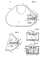
- a cartridge 10 having a take-up spool 12 extending outwardly through an opening 16 formed by side wall 14.
- This exposure of take-up spool 12 through opening 16, formed by side wall 14, allows access by drive roller 18 to the periphery of take-up spool 12 or the periphery of ribbon disk 20 as the ribbon disk diameter grows.
- Ribbon disk 20 is accumulated and increases in diameter as consumed ribbon 22 is wound onto take-up spool 12 by the action of drive roller 18 rotating thereagainst.
- Web member 24 is shown covering the guide surfaces 26 formed in the top wall of cartridge 10.
- Guide surfaces 26 are conventionally formed during the molding operation by means of inserts in a mold to yield a guide slot 27 through which axle 28 of take-up spool 12 may protrude by a short distance.
- Axle 28 will extend sufficiently through guide slot 27 to extend beyond and exteriorally of the plane defined by frangible web 24.
- Frangible web 24 may be provided with an aperture through which axle 28 may be inserted during assembly or may be provided only as a solid sheet with the axle 28 being forcibly pierced therethrough during assembly.
- Figure 2 is a partial view of the cartridge 10 of figure 1 but illustrates frangible web member 24 after axle 28 has translated a substantial portion of its translatory path defined by guide slot 27. Frangible web 24 is ruptured during the translation of axle 28 and the torn edges of web 24 are shown at 30.
- FIG. 3 more clearly illustrates the guide slot 27 in the top wall 32 of cartridge 10. Overlaying the portion of the top wall 32 which acts to define guide slot 27 and adhered or sealed thereto is web 24.
- Figure 4 illustrates the same view of the cartridge as in figure 3 with the axle 28 extending through web 24 and shows the torn edges 30 of web 24.
- Take-up spool 12 is illustrated surrounding axle 28.
- a substantially identical web 38 is attached and bonded to the bottom wall 34 for the bottom end of axle 28 to engage.
- a guide slot 37 is formed and defined by guide surfaces 36 of bottom wall 34. This guide slot 37 is functionally identical to the guide slot 27 in the top wall 32 of cartridge 10.
- web 24 may be a thin piece or sheet or material such as polyethylene terephthalate or comparable sheet plastic.
- material such as polyethylene terephthalate or comparable sheet plastic.
- FIG. 5 illustrates web 38 as undisturbed and with the take-up spool 12 proximate to the opening 16 formed by side wall 14 of cartridge 10.
- Figure 6 is an identical view of the cartridge 10 except for the translation of axle 28 along the guide slot 37 leaving web 38 fractured and torn with the torn surfaces 30 illustrated to the left of axle 28.
- FIG. 7 illustrates an alternate embodiment of the invention.
- Cartridge 10 is shown with the top wall 32 and bottom wall 34.
- Formed into top wall 32 is a channel 27 having guide surfaces 26 formed into the thickness of the top wall 32.
- the web portions 40 in top wall 32 and in bottom wall 34 are formed by leaving a flash, in the molding operation, extending across guide slots 27, 37 formed by surfaces 26 and 36. This flash or thin and thus weakened wall section will break as axle 28 translates in the guide slots 27, 37 and perform in the same manner as the webs 24 and 38 illustrated in figures 3 and 4.
Landscapes
- Impression-Transfer Materials And Handling Thereof (AREA)
- Photographic Developing Apparatuses (AREA)
- Automatic Tape Cassette Changers (AREA)
- Measurement And Recording Of Electrical Phenomena And Electrical Characteristics Of The Living Body (AREA)
Abstract
Description
- This invention relates to cartridges for spooled webs and particularly to cartridges for ribbons for use on typewriters and printers.
- Ribbon cartridges are known which include a ribbon take-up spool continuously spring biased in peripheral driving engagement with a drive roller having a spacially axis of rotation. In order to accomodate ribbon accumulation on the take-up spool, the axle thereof is shiftably mounted within the cartridge. Such ribbon cartridges are disclosed, for example, in the document FR-A-2,391,853.
- The manufacture of ribbon cartridges which utilize a translating take-up spool and require springs and spring guides for proper assembly and operation is expensive due, not only to the cost of the parts but also, to the expense of assembly.
- The expense of a spring and spring guide is not justified from the standpoint that the spring is a long-term functional element inherently possessing re-use capability. However, the discarding of cartridges after the consumption of the ribbon contained therein wastes the re-use capability of the parts and thus derives no benefit from the increased cost.
- Accordingly, it is the object of the invention to simplify a single use cartridge having a translating take-up spool to reduce the cost thereof.
- The ribbon cartridge according to the invention is of the type described in the above-mentioned document FR-A-2,391,853. It comprises top, bottom and side walls and at least a take-up spool including an axle. The take-up spool and axle are movable within the cartridge from a position adjacent to the side wall to a position displaced from said side wall, as the ribbon accumulates on the take-up spool. Restraining means acting on the axle resist the take-up spool displacement caused by the ribbon accumulation. The cartridge according to the invention is characterized in that the restraining means comprises a frangible member in the top and bottom walls and engaging said axle, whereby said axle breaks said member progressively as said axle and said take-up spool move away from said position adjacent to the side wall.
-
- Figure 1 illustrates the general configuration of a cartridge having a translating take-up spool together with a frangible web resistance member attached to the top surface thereof.
- Figure 2 illustrates the position occupied by the take-up spool axle after having accumulated a substantially full ribbon disk of consumed ribbon.
- Figure 3 illustrates the frangible web members in a position mounted on and bonded to the cartridge structure.
- Figure 4 shows a section along section line IV-IV in figure 1 with an axle of the take-up spool extending therethrough and breaking the frangible webs.
- Figure 5 is a bottom view of the cartridge as shown in figure 1 with a frangible web member resisting the axle of the take-up spool on the bottom side thereof.
- Figure 6 is a bottom view of the cartridge with the take-up spool having accumulated essentially full ribbon disk of consumed ribbon;
- Figure 7 shows a section along line VII-VII in figure 1 and illustrates an alternative embodiment of the frangible web section wherein the web section is formed as an integral part of the cartridge wall structure during molding.
- Referring to figure 1, there is illustrated a
cartridge 10 having a take-up spool 12 extending outwardly through anopening 16 formed byside wall 14. This exposure of take-up spool 12 throughopening 16, formed byside wall 14, allows access bydrive roller 18 to the periphery of take-up spool 12 or the periphery ofribbon disk 20 as the ribbon disk diameter grows.Ribbon disk 20 is accumulated and increases in diameter as consumedribbon 22 is wound onto take-up spool 12 by the action ofdrive roller 18 rotating thereagainst. -
Web member 24 is shown covering theguide surfaces 26 formed in the top wall ofcartridge 10.Guide surfaces 26 are conventionally formed during the molding operation by means of inserts in a mold to yield aguide slot 27 through whichaxle 28 of take-up spool 12 may protrude by a short distance. Axle 28 will extend sufficiently throughguide slot 27 to extend beyond and exteriorally of the plane defined byfrangible web 24.Frangible web 24 may be provided with an aperture through whichaxle 28 may be inserted during assembly or may be provided only as a solid sheet with theaxle 28 being forcibly pierced therethrough during assembly. - As take-
up spool 12 is forced to translate due to the increasing diameter ofribbon disk 20, the force of the spool on theaxle 28 will increase and will continue to increase and create a stress onweb 24 until such time as the rupture strength of the web is exceeded. This will create a localized tearing or breaking ofweb 24 allowingaxle 28 to translate an incremental amount, thus relieving the forces exerted onaxle 28 until such time as additional ribbon is accumulated on take-up spool 12, thus increasing the forces again to exceed the rupture strength at the web. - Figure 2 is a partial view of the
cartridge 10 of figure 1 but illustratesfrangible web member 24 afteraxle 28 has translated a substantial portion of its translatory path defined byguide slot 27.Frangible web 24 is ruptured during the translation ofaxle 28 and the torn edges ofweb 24 are shown at 30. - Figure 3 more clearly illustrates the
guide slot 27 in thetop wall 32 ofcartridge 10. Overlaying the portion of thetop wall 32 which acts to defineguide slot 27 and adhered or sealed thereto isweb 24. - Figure 4 illustrates the same view of the cartridge as in figure 3 with the
axle 28 extending throughweb 24 and shows thetorn edges 30 ofweb 24. Take-upspool 12 is illustrated surroundingaxle 28. A substantiallyidentical web 38 is attached and bonded to thebottom wall 34 for the bottom end ofaxle 28 to engage. Aguide slot 37 is formed and defined byguide surfaces 36 ofbottom wall 34. Thisguide slot 37 is functionally identical to theguide slot 27 in thetop wall 32 ofcartridge 10. - In the embodiments illustrated in figures 1-4,
web 24 may be a thin piece or sheet or material such as polyethylene terephthalate or comparable sheet plastic. There appears to be nothing critical in the selection of the material so long as the material is sufficiently resistive to tearing that the resistance exerted by the material, prior to rupture, onaxle 28 is enough to insure engagement between the periphery ofribbon disk 20 anddrive roller 18 throughaperture 16 formed byside wall 14 ofcartridge 10. The rupture or tearing strength ofwebs axle 28, take-up .spool 12 and the periphery ofribbon disk 20 to driveroller 18. - Referring to figures 5 and 6,
web 38 is illustrated in two conditions. Figure 5 illustratesweb 38 as undisturbed and with the take-up spool 12 proximate to theopening 16 formed byside wall 14 ofcartridge 10. Figure 6 is an identical view of thecartridge 10 except for the translation ofaxle 28 along theguide slot 37 leavingweb 38 fractured and torn with thetorn surfaces 30 illustrated to the left ofaxle 28. - Figure 7 illustrates an alternate embodiment of the invention.
Cartridge 10 is shown with thetop wall 32 andbottom wall 34. Formed intotop wall 32 is achannel 27 havingguide surfaces 26 formed into the thickness of thetop wall 32. Theweb portions 40 intop wall 32 and inbottom wall 34 are formed by leaving a flash, in the molding operation, extending acrossguide slots surfaces axle 28 translates in theguide slots webs - While the invention is shown in the foregoing embodiments, changes and modifications may be made by one of skill in the art within the scope of the invention.
Claims (4)
said ribbon cartridge (10) being characterized in that said restraining means (24, 38, 40) comprises a frangible member in said top and bottom walls (32, 34) and engaging said axle means (28), whereby said axle means (28) breaks said member progressively as said axle means (28) and said take-up spool (12) move away from said position adjacent to said side wall (14).
Priority Applications (1)
| Application Number | Priority Date | Filing Date | Title |
|---|---|---|---|
| AT81108562T ATE9076T1 (en) | 1980-12-08 | 1981-10-20 | DISPOSABLE RIBBON CARTRIDGE WITH A FRAGILE RESISTOR ELEMENT TO SLOW DOWN THE LATERAL DEFLECTION OF THE TAKE-UP COIL. |
Applications Claiming Priority (2)
| Application Number | Priority Date | Filing Date | Title |
|---|---|---|---|
| US06/213,718 US4329073A (en) | 1980-12-08 | 1980-12-08 | Single use ribbon cartridge with frangible resistive element for restraining the takeup spool |
| US213718 | 1980-12-08 |
Publications (3)
| Publication Number | Publication Date |
|---|---|
| EP0053685A2 true EP0053685A2 (en) | 1982-06-16 |
| EP0053685A3 EP0053685A3 (en) | 1982-07-21 |
| EP0053685B1 EP0053685B1 (en) | 1984-08-22 |
Family
ID=22796228
Family Applications (1)
| Application Number | Title | Priority Date | Filing Date |
|---|---|---|---|
| EP81108562A Expired EP0053685B1 (en) | 1980-12-08 | 1981-10-20 | Single use ribbon cartridge with frangible resistive element for restraining the translating take-up spool |
Country Status (9)
| Country | Link |
|---|---|
| US (1) | US4329073A (en) |
| EP (1) | EP0053685B1 (en) |
| JP (1) | JPS6026717B2 (en) |
| AT (1) | ATE9076T1 (en) |
| AU (1) | AU541050B2 (en) |
| CA (1) | CA1151129A (en) |
| DE (1) | DE3165702D1 (en) |
| ES (1) | ES8300579A1 (en) |
| NZ (1) | NZ198627A (en) |
Families Citing this family (9)
| Publication number | Priority date | Publication date | Assignee | Title |
|---|---|---|---|---|
| US4451166A (en) * | 1982-03-03 | 1984-05-29 | Triumph-Adler A.G. Fur Buround Informationstechnik | Inked ribbon cartridge with ribbon drag device |
| JPS5921961U (en) * | 1982-08-03 | 1984-02-10 | キャノン・エヌ・ティー・シー株式会社 | Typewriter ribbon winding device |
| NL8300476A (en) * | 1983-02-09 | 1984-09-03 | Philips Nv | MAGNETIC TAPE CASSETTE. |
| EP0545898A3 (en) * | 1987-04-25 | 1993-06-30 | Canon Kabushiki Kaisha | Ink ribbon cassette |
| DE3741361A1 (en) * | 1987-12-07 | 1989-06-15 | Triumph Adler Ag | CARRIER OF A RIBBON FOR WRITING AND SIMILAR MACHINES |
| US4998833A (en) * | 1990-01-17 | 1991-03-12 | Hwang Chiman | Refillable ink ribbon cartridge for use in an electronic typewriter |
| US5826991A (en) * | 1996-01-19 | 1998-10-27 | Interbold | Printer apparatus for automated banking machine |
| US7213990B2 (en) | 2004-03-15 | 2007-05-08 | Brother Kogyo Kabushiki Kaisha | Ink ribbon cartridge |
| US20150108122A1 (en) * | 2013-10-18 | 2015-04-23 | Ronald C. Jimdar | Selectable Volume Container |
Family Cites Families (11)
| Publication number | Priority date | Publication date | Assignee | Title |
|---|---|---|---|---|
| US459379A (en) * | 1891-09-08 | Third to frederick c | ||
| US769928A (en) * | 1903-01-23 | 1904-09-13 | John W Slater | Non-collapsible paint tube or receptacle. |
| US2717101A (en) * | 1949-05-04 | 1955-09-06 | Ambrose B Van Handel | Paste-type dentifrice dispensing toothbrush |
| US2804508A (en) * | 1954-07-31 | 1957-08-27 | Ernst Mastling | Tape reproducer |
| US3011691A (en) * | 1959-04-27 | 1961-12-05 | Dorothy S Mcglynn | Envelope |
| US3520495A (en) * | 1966-10-29 | 1970-07-14 | Tadashi Sotani | Tape cartridge and driving mechanism for the tape |
| IT1024899B (en) * | 1974-11-25 | 1978-07-20 | Olivetti Ing C S P A | REMOVABLE CARTRIDGE FOR A CAREON TAPE OF TELESCRIPTING ACCOUNTING MACHINES AND SIMILAR OFFICE MACHINES |
| US4347007A (en) * | 1977-05-27 | 1982-08-31 | International Business Machines Corporation | Typewriter cartridge and feed mechanism therefor |
| JPS55101560A (en) * | 1979-01-23 | 1980-08-02 | Murata Mach Ltd | Method and apparatus for joining spum yarns |
| DE2951610C2 (en) * | 1979-12-21 | 1987-03-26 | Olympia AG, 2940 Wilhelmshaven | Ribbon cassette for a typewriter or similar office machine |
| US4272201A (en) * | 1980-02-19 | 1981-06-09 | International Business Machines Corporation | Ribbon shaper for typewriter cartridge |
-
1980
- 1980-12-08 US US06/213,718 patent/US4329073A/en not_active Expired - Lifetime
-
1981
- 1981-09-03 JP JP56137893A patent/JPS6026717B2/en not_active Expired
- 1981-10-09 CA CA000387640A patent/CA1151129A/en not_active Expired
- 1981-10-13 NZ NZ198627A patent/NZ198627A/en unknown
- 1981-10-20 EP EP81108562A patent/EP0053685B1/en not_active Expired
- 1981-10-20 AT AT81108562T patent/ATE9076T1/en active
- 1981-10-20 DE DE8181108562T patent/DE3165702D1/en not_active Expired
- 1981-11-20 AU AU77691/81A patent/AU541050B2/en not_active Ceased
- 1981-12-07 ES ES507762A patent/ES8300579A1/en not_active Expired
Also Published As
| Publication number | Publication date |
|---|---|
| AU541050B2 (en) | 1984-12-13 |
| AU7769181A (en) | 1982-06-17 |
| ES507762A0 (en) | 1982-11-01 |
| DE3165702D1 (en) | 1984-09-27 |
| US4329073A (en) | 1982-05-11 |
| ATE9076T1 (en) | 1984-09-15 |
| JPS6026717B2 (en) | 1985-06-25 |
| CA1151129A (en) | 1983-08-02 |
| EP0053685A3 (en) | 1982-07-21 |
| EP0053685B1 (en) | 1984-08-22 |
| ES8300579A1 (en) | 1982-11-01 |
| JPS5796888A (en) | 1982-06-16 |
| NZ198627A (en) | 1984-08-24 |
Similar Documents
| Publication | Publication Date | Title |
|---|---|---|
| EP0053685B1 (en) | Single use ribbon cartridge with frangible resistive element for restraining the translating take-up spool | |
| US3604549A (en) | Dual feed rate ribbon mechanism and supply cartridge therefor | |
| US4983058A (en) | Tape holding case | |
| EP1707395B1 (en) | Tape cassette | |
| EP0170504B1 (en) | Print ribbon cassette | |
| AU2015243050A1 (en) | Tape cassette and tape printer | |
| EP0096545B1 (en) | Typing ribbon cartridge with blocking element | |
| EP0360400B1 (en) | Web roll holding device | |
| IE51276B1 (en) | Anti-reversal device for printer ribbon cartridge take-up spool | |
| KR100418840B1 (en) | Cartridge and cartridge for consumable ribbon | |
| EP0066689B1 (en) | Ribbon feed mode shift mechanism | |
| EP3666530B1 (en) | Portable printer | |
| EP0004047B1 (en) | Ribbon cartridge | |
| US4026492A (en) | Ribbon tension control means | |
| US5738448A (en) | Ribbon cassette for printer | |
| US6347895B1 (en) | Printer cartridge with breakable frangible member | |
| US4209139A (en) | Power driven paper take-up mechanism | |
| EP0224347B1 (en) | Ribbon cassette for printers | |
| KR960007404A (en) | Paper ejector | |
| JPS62271776A (en) | Endless ink ribbon cassette | |
| US3612242A (en) | Automatic ribbon takeup | |
| CA1243289A (en) | Tape-ribbon cartridge | |
| JPH0331150B2 (en) | ||
| JP3901176B2 (en) | Tape cassette and tape printer | |
| JP4062344B2 (en) | Tape cassette and tape printer |
Legal Events
| Date | Code | Title | Description |
|---|---|---|---|
| PUAI | Public reference made under article 153(3) epc to a published international application that has entered the european phase |
Free format text: ORIGINAL CODE: 0009012 |
|
| PUAL | Search report despatched |
Free format text: ORIGINAL CODE: 0009013 |
|
| 17P | Request for examination filed |
Effective date: 19811020 |
|
| AK | Designated contracting states |
Designated state(s): AT BE CH DE FR GB IT NL SE |
|
| AK | Designated contracting states |
Designated state(s): AT BE CH DE FR GB IT NL SE |
|
| ITF | It: translation for a ep patent filed | ||
| GRAA | (expected) grant |
Free format text: ORIGINAL CODE: 0009210 |
|
| AK | Designated contracting states |
Designated state(s): AT BE CH DE FR GB IT LI NL SE |
|
| REF | Corresponds to: |
Ref document number: 9076 Country of ref document: AT Date of ref document: 19840915 Kind code of ref document: T |
|
| REF | Corresponds to: |
Ref document number: 3165702 Country of ref document: DE Date of ref document: 19840927 |
|
| ET | Fr: translation filed | ||
| PLBE | No opposition filed within time limit |
Free format text: ORIGINAL CODE: 0009261 |
|
| STAA | Information on the status of an ep patent application or granted ep patent |
Free format text: STATUS: NO OPPOSITION FILED WITHIN TIME LIMIT |
|
| 26N | No opposition filed | ||
| REG | Reference to a national code |
Ref country code: FR Ref legal event code: GC |
|
| REG | Reference to a national code |
Ref country code: CH Ref legal event code: PUE Owner name: LEXMARK INTERNATIONAL, INC. |
|
| REG | Reference to a national code |
Ref country code: GB Ref legal event code: 732 |
|
| REG | Reference to a national code |
Ref country code: FR Ref legal event code: TP |
|
| ITPR | It: changes in ownership of a european patent |
Owner name: CESSIONE;LEXMARK INTERNATIONAL INC. |
|
| NLS | Nl: assignments of ep-patents |
Owner name: LEXMARK INTERNATIONAL, INC. TE LEXINGTON, KENTUCKY |
|
| ITPR | It: changes in ownership of a european patent |
Owner name: PEGNO;J.P. MORGAN DELAWARE |
|
| REG | Reference to a national code |
Ref country code: CH Ref legal event code: PVP Owner name: J.P. MORGAN DELAWARE |
|
| ITTA | It: last paid annual fee | ||
| EAL | Se: european patent in force in sweden |
Ref document number: 81108562.0 |
|
| PGFP | Annual fee paid to national office [announced via postgrant information from national office to epo] |
Ref country code: SE Payment date: 19950913 Year of fee payment: 15 Ref country code: NL Payment date: 19950913 Year of fee payment: 15 Ref country code: FR Payment date: 19950913 Year of fee payment: 15 Ref country code: CH Payment date: 19950913 Year of fee payment: 15 |
|
| PGFP | Annual fee paid to national office [announced via postgrant information from national office to epo] |
Ref country code: AT Payment date: 19950915 Year of fee payment: 15 |
|
| PGFP | Annual fee paid to national office [announced via postgrant information from national office to epo] |
Ref country code: DE Payment date: 19950925 Year of fee payment: 15 Ref country code: BE Payment date: 19950925 Year of fee payment: 15 |
|
| PGFP | Annual fee paid to national office [announced via postgrant information from national office to epo] |
Ref country code: GB Payment date: 19950927 Year of fee payment: 15 |
|
| PG25 | Lapsed in a contracting state [announced via postgrant information from national office to epo] |
Ref country code: GB Effective date: 19961020 Ref country code: AT Effective date: 19961020 |
|
| PG25 | Lapsed in a contracting state [announced via postgrant information from national office to epo] |
Ref country code: SE Effective date: 19961021 |
|
| PG25 | Lapsed in a contracting state [announced via postgrant information from national office to epo] |
Ref country code: LI Effective date: 19961031 Ref country code: CH Effective date: 19961031 Ref country code: BE Effective date: 19961031 |
|
| BERE | Be: lapsed |
Owner name: LEXMARK INTERNATIONAL INC. Effective date: 19961031 |
|
| PG25 | Lapsed in a contracting state [announced via postgrant information from national office to epo] |
Ref country code: NL Effective date: 19970501 |
|
| GBPC | Gb: european patent ceased through non-payment of renewal fee |
Effective date: 19961020 |
|
| REG | Reference to a national code |
Ref country code: CH Ref legal event code: PL |
|
| PG25 | Lapsed in a contracting state [announced via postgrant information from national office to epo] |
Ref country code: FR Effective date: 19970630 |
|
| NLV4 | Nl: lapsed or anulled due to non-payment of the annual fee |
Effective date: 19970501 |
|
| PG25 | Lapsed in a contracting state [announced via postgrant information from national office to epo] |
Ref country code: DE Effective date: 19970701 |
|
| EUG | Se: european patent has lapsed |
Ref document number: 81108562.0 |
|
| REG | Reference to a national code |
Ref country code: FR Ref legal event code: ST |