EP0053468A2 - Liquid ink drop generator - Google Patents
Liquid ink drop generator Download PDFInfo
- Publication number
- EP0053468A2 EP0053468A2 EP81305538A EP81305538A EP0053468A2 EP 0053468 A2 EP0053468 A2 EP 0053468A2 EP 81305538 A EP81305538 A EP 81305538A EP 81305538 A EP81305538 A EP 81305538A EP 0053468 A2 EP0053468 A2 EP 0053468A2
- Authority
- EP
- European Patent Office
- Prior art keywords
- liquid
- generator
- nozzle
- cavity
- drop
- Prior art date
- Legal status (The legal status is an assumption and is not a legal conclusion. Google has not performed a legal analysis and makes no representation as to the accuracy of the status listed.)
- Granted
Links
Images


Classifications
-
- B—PERFORMING OPERATIONS; TRANSPORTING
- B41—PRINTING; LINING MACHINES; TYPEWRITERS; STAMPS
- B41J—TYPEWRITERS; SELECTIVE PRINTING MECHANISMS, i.e. MECHANISMS PRINTING OTHERWISE THAN FROM A FORME; CORRECTION OF TYPOGRAPHICAL ERRORS
- B41J2/00—Typewriters or selective printing mechanisms characterised by the printing or marking process for which they are designed
- B41J2/005—Typewriters or selective printing mechanisms characterised by the printing or marking process for which they are designed characterised by bringing liquid or particles selectively into contact with a printing material
- B41J2/01—Ink jet
- B41J2/015—Ink jet characterised by the jet generation process
- B41J2/02—Ink jet characterised by the jet generation process generating a continuous ink jet
- B41J2/03—Ink jet characterised by the jet generation process generating a continuous ink jet by pressure
-
- B—PERFORMING OPERATIONS; TRANSPORTING
- B41—PRINTING; LINING MACHINES; TYPEWRITERS; STAMPS
- B41J—TYPEWRITERS; SELECTIVE PRINTING MECHANISMS, i.e. MECHANISMS PRINTING OTHERWISE THAN FROM A FORME; CORRECTION OF TYPOGRAPHICAL ERRORS
- B41J2/00—Typewriters or selective printing mechanisms characterised by the printing or marking process for which they are designed
- B41J2/005—Typewriters or selective printing mechanisms characterised by the printing or marking process for which they are designed characterised by bringing liquid or particles selectively into contact with a printing material
- B41J2/01—Ink jet
- B41J2/135—Nozzles
- B41J2/145—Arrangement thereof
- B41J2/155—Arrangement thereof for line printing
-
- Y—GENERAL TAGGING OF NEW TECHNOLOGICAL DEVELOPMENTS; GENERAL TAGGING OF CROSS-SECTIONAL TECHNOLOGIES SPANNING OVER SEVERAL SECTIONS OF THE IPC; TECHNICAL SUBJECTS COVERED BY FORMER USPC CROSS-REFERENCE ART COLLECTIONS [XRACs] AND DIGESTS
- Y10—TECHNICAL SUBJECTS COVERED BY FORMER USPC
- Y10S—TECHNICAL SUBJECTS COVERED BY FORMER USPC CROSS-REFERENCE ART COLLECTIONS [XRACs] AND DIGESTS
- Y10S310/00—Electrical generator or motor structure
- Y10S310/80—Piezoelectric polymers, e.g. PVDF
Definitions
- This invention relates to ink jet or liquid drop recording, printing and the like systems.
- this invention relates to a liquid drop generator comprising a body member including a liquid cavity between a backing plate and a nozzle plate, said nozzle plate including at least one nozzle means for emitting a liquid column due to pressure in the cavity, conduit means for coupling a liquid under pressure to the liquid cavity for emitting a liquid column through the nozzle means from which the drops are formed and a piezoelectric exciter coupled to the body member to acoustically stimulate a liquid in the liquid cavity.
- Liquid drop generators of the present type are described by Sweet in U.S. Patent 3,596,275. Drops are generated continuously from a column of liquid emitted under pressure from a chamber via a nozzle. As characterised by Lord Rayleigh, drops continuously separate from the end of the liquid column in a predictable fashion. The uniformity of drop size and spacing are improved by stimulating the liquid at a fixed frequency. In addition, the stimulation stabilizes the location of drop separation from the liquid column. This is important for controlling the process of charging the drops by a charging electrode tunnel located at the drop separation region.
- a widebank ink jet modulator using a thin piezoelectric crystal is disclosed in U.S. Patent 4,032,928 to White and Lovelady. That patent also discloses a multiple nozzle drop generator in the embodiment of Figure 8.
- the single nozzle modulator 10 in Figures 1, 2, 3, 4 and 5 of White et al and the multi-nozzle modulator 101 in Figure 8 are truly miniature devices. That is, the thickness of the entire modulator is small compared to the smallest standing acoustic wave that can be established in the part in question. However, the width of the device is also confined to a small dimension 9.5 mm.
- the multi-nozzle embodiment of Figure 8 is reported as equal in configuration to the single nozzle device 10 in Figures 1-5.
- start up and shut down of an ink drop generator is troublesome in single as well as multi-nozzle drop generators.
- the liquid can cause electrical shorting and other problems if a liquid column and its drop stream are not appropriately handled at start up and shut off.
- the present invention is intended to provide a liquid drop generator that overcomes the limitations of prior art generators, and which is capable of generating drops over a wide range of drop generation rates or frequencies.
- the invention is characterised in that in a liquid drop generator of the kind described, the backing plate, the piezoelectric exciter, the liquid cavity and the nozzle plate each has a dimension in the direction of liquid emission which is small compared with its dimensions in the plane to which said direction is normal, and in that the piezolectric exciter is a flexible member.
- the generator of this invention has a low volume liquid cavity or chamber from which liquid drop streams are emitted to improve the start up and shut down ability of a drop generator of the present type. Furthermore, the generator has a plurality of nozzles extending over a significant distance such as a 21.6 cm document width in an ink jet printer. The use of a thin liquid chamber does not adversely impact the acoustic performance of the generator.
- the preferred embodiment includes a polyvinylidene fluoride (PVF 2 ) film as the acoustic exciter.
- the exciter is sandwiched between a backing plate and a transmission block.
- the thin liquid chamber is formed in a gap between the transmission block and a nozzle plate.
- the transmission block serves to chemically isolate the PVF 2 film and to provide means for coupling a liquid supply to the thin chamber.
- the nozzle plate contains the nozzle or nozzles for emitting the liquid drop streams. It may be characterised as a mass coupled to a spring.
- the spring is the liquid in the thin cavity.
- the nozzle plate is oscillated by the acoustic waves generated by the PVF 2 exciter.
- the backing plate, transmission plate, liquid chamber and nozzle plate are all thin. That is, their thickness are small compared to a half wavelength of the acoustic waves in the plates and liquid at the frequency of the drop generation rate.
- the transmission block and nozzle plate may include liquid moats to isolate the generator body from the acoustic excitation.
- the backing plate may include air moats to isolate the generator body from the PVF 2 exciter oscillations.
- a special suspension means is provided for the nozzle plate to enable it to act as the mass on the spring and for the backing and transmission plates to confine the acoustic energy to the region of the liquid chamber.
- the nozzle plate has adequate thickness to withstand the liquid pressure in the thin chamber yet is thin enough to resonate as a mass spring at the desired drop generation rate.
- the thin body generator 1 in Figure 1 includes a backing plate 2, a thin piezoelectric exciter 3, a transmission block 4, a liquid chamber 5 and a nozzle plate 6.
- the exciter includes an electrically poled polyvinylidene fluoride (PVF 2 ) film 7 having electrodes 8 and 9 on opposite sides of the film.
- the electrodes or leads 8 and 9 are electrically coupled to an AC voltage source 10 to electrically activate the film.
- the activated film generates acoustic oscillations at the frequency of the AC source.
- a suitable AC signal frequency is 100 kHz .
- the oscillation frequency of the exciter 3 determines the drop generation rate, in this example 100 thousand drops per second.
- Spacers 11 between the transmission block and nozzle plate along with plates 4 and 6 define the cavity or chamber 5.
- Drops are produced from liquid fed into the chamber 5 under pressure.
- the liquid pressure forces a column 13 (see Figure 4) of liquid out of the generator 1 through a nozzle 14.
- the column breaks up into drops 15 (see Figure 4) at some finite distance from the nozzle.
- the break up point remains constant as do the size and spacing of the drops due to the fixed frequency, acoustic stimulation of the liquid by exciter 3.
- the exciter 3 is preferably an electrically poled, PVF 2 film of the type disclosed in European Patent Publication No. 0020182, to which the reader is referred for a more detailed explanation.
- the term piezoelectric, as used herein, is meant to include not only a piezoelectric response exhibited by a structure but also an electrostrictive response exhibited by a structure. Broadly, the present piezoelectric exciter is intended to define those devices that convert AC electrical energy into AC mechanical or acoustic energy.
- the exciter, PVF 2 film 7, including the electrodes 8 and 9, is about 25 microns thick.
- the lowest acoustic resonant frequency associated with a PVF 2 exciter of such thickness is well above the 50-250 kHz drop generation frequencies of interest in ink jet printing systems. Consequently, the exciter 3 is operated at a non-resonant frequency which is contrary to prior art experience.
- Conventional practice is to drive an exciter at its lowest or a multiple resonant frequency because the maximum coupling of the acoustic energy to a liquid is realized at a resonant frequency.
- An exception to the conventional practice is the usage reported by White et al in U.S. Patent 4,032,92.8 supra.
- White et al is limited to a specific miniature drop modulator that is not merely thin but also very narrow.
- the narrowness of the structure reported by White et a makes the device unsuited for generating a plurality of streams spanning all or large portions of the width of a target, e.g. a 21.6 cm or 27.9 cm dimension of a plain paper target.
- the exciter 1 is successful as a wide, multiple nozzle drop generator for reasons that include the use of polymer exciters such as PVF 2 films.
- the miniature modulator of White et al succeeds simply because of its exceptionally small scale in width as well as thickness.
- the exciter 1 also differs from the White et al exciter in other ways. One dramatic difference is that exciter 1 employs a transmission block 4. Another dramatic difference is that exciter 1 employs a comparatively thick backing plate 2.
- the thickness of the backing plate 2 and transmission plate or block 4 are selected such that the acoustic resonant frequency of the composite layers 2, 3 and 4 is still well above the desired drop generation frequency. For this reason, the present drop generators are substantially different from those of the prior art.
- the thickness "a” (see Figure 1) of the backing plate 2 is made large compared to that shown in Figure 3 of the White et al patent 4,032,928 wherein the thickness of a backing plate is represented as less than that of the piezoelectric crystal.
- the thickness "b" of the transmission block 4 is selected here to be equal to or less than that of the backing plate, a thin diaphram is disclosed in White et al rather than a transmission block.
- the transmission block chemically isolates the exciter 3 from the liquid in the chamber 5. It also has adequate thickness for accommodating the fluid or liquid infeed conduit 16.
- the infeed pipe 16 is coupled to an external conduit 17 which in turn is in fluid communication with a pressurized liquid source represented by the arrow 18.
- the chamber thickness "c" (see Figure 1) is very small. Specifically, it is significantly less than that of the transmission plate or nozzle plate. Its thickness is selected such that there is substantially no difference in the acoustic pressure across the dimension "c". This condition permits the generator to be characterized or analogized to a mass on a spring. The mass is the nozzle plate and the spring is the liquid in chamber 5. The motion or displacement of wall 20 of the transmission block due to the oscillation of exciter 3 is imparted to the nozzle plate 6 by the liquid. The result is that the static pressure of the liquid in chamber 5 is varied by some amount at the frequency established by the AC voltage source 10. These pressure variations in turn cause drops 15 ( Figure 4) to be generated at the frequency of source 10.
- Past generators while successful, have shown some non-uniformity from drop stream to drop stream in multiple nozzle generators.
- the cause of this is due, at least in part, to the interaction of the acoustic waves in the liquid chamber and the acoustic waves in the body of the generator, i.e. the walls, backing plates and the like.
- the thin body generators of the present invention are designed to confine the acoustic energy to a small volume of liquid, i.e. the liquid 12 in chamber 5, made with very simple parts.
- the thickness of chamber 5 forces offensive transverse compressional acoustic wave modes to occur at frequencies far in excess of the drop generation rate.
- the thickness "c" of chamber 5, according to the present concept, should be less than 5 percent of the wavelength of sound in the liquid at the drop rate.
- the thickness "a" of the backing plate 2 is made as large as permissible while remaining thin in terms of percent of wavelength.
- the ideal is to have the backing plate wall 21 at rest so that the total thickness changes in the exciter 3 are applied to the transmission block 4. Accordingly, the dimension "a" of a backing plate should be about 5 percent of L B , the acoustic wavelength at the drop rate in the backing plate material.
- the backing plate 21, transmission block 4 and nozzle plate 6 are composed of stainless steel, the presently preferred material.
- the transmission block thickness "b" should be equal to or less than that of "a” when both are made of the same material. Otherwise, the dimension “b” should also be equal to or less than about 5 percent of L T , the acoustic wavelength in the block 4 at the desired drop rate or range of drop rates. This condition is readily met because of the thinness of the plates.
- the dimension "d" for nozzle plate 6 is selected to be compatible with the foregoing.
- the thickness "d” should be large enough to enable the nozzle plate to contain the liquid in chamber 5. It should also be thin to reduce acoustic pressure drop within the nozzle 14 formed in plate 6.
- the nozzle plate 6 may be viewed as a mass vibrating on a spring, i.e. the liquid in chamber 5. If this mass and spring system is operated at its resonant frequency, significant pressure variations are developed in the liquid.
- the resonant frequency is of course, selected to be near that of the range of desired drop rates.
- the resonant frequency f is defined by where P and P n are the densities of the liquid and nozzle plate, C is the speed of an acoustic wave in the liquid, and "c" and "d” are the thicknesses of the chamber 5 and plate 6 shown in Figures 1 and 2.
- the dimension "e” is selected by setting the value of "e” to one half the acoustic wavelength in the liquid at the drop rate. This is defined by the expression where L f is the acoustic wavelength in the liquid, C f the acoustic speed in the liquid and f the drop rate.
- the foregoing discussion describes in terms of drop frequency or rate the thin drop generator of this invention.
- the generator 25 of Figure 2 has its dimensions a-e selected in the same manner.
- Generator 25 is the presently preferred embodiment of the present invention, however, because it includes moats for isolating the acoustic energy in the region of a liquid chamber.
- Generator 25 also includes novel suspension means for the backing plate, transmission block and nozzle plate which act to insulate the supporting structure from the acoustic vibrations.
- Generator 25 includes: backing plate 26; pizoelectric exciter 27; transmission plate 28; liquid chamber 29; and nozzle plate 30.
- the nozzle plate contains a plurality of nozzles 31 that extend for a significant distance 1. (See the isometric view in Figure 3.)
- the infeed conduit 32 is coupled to the external conduit 33 that couples a liquid 33 into chamber 29 from a pressurized source represented by arrow 34.
- the active acoustic parts of generator 25 are those within the elevation"e" as shown.
- the regions above and below the dimension "e” constitute the support structure for the generator.
- the active parts are held in place by thin regions or suspension means of the backing, transmission and nozzle plates identified by the dashed circles 36 at six places in Figures 2 and 3.
- the suspension means or regions extend the length 1 of generator 25.
- Each suspension region has a uniform cross-section with dimensions h and T as shown in Figure 2.
- the h and T dimensions are the smallest possible for the most critical element; namely, the nozzle plate 30.
- the like dimensions for the suspension regions on the backing plate 26 and transmission plate 28 are by necessity adequate.
- the suspension regions also define the moats.
- the generator 25 includes upper and lower air moats 37 and 38 and upper and lower liquid moats 39 and 40.
- the moats 37-40 extend across the width of the generator.
- the x, y and z orthogonal vectors of an x, y and z orthogonal coordinate system are shown in all the figures.
- the z axis is the direction of the drop streams and the axis along which the thicknesses "a", “b", “c” and “T” are measured.
- the y axis is the axis along which the heights "e” and "h” are measured.
- the x axis is the axis along which the plurality of nozzles 31 are arranged over a length 1.
- the air moats 37 and 38 are formed in the backing plate 26. Their purpose is to confine the acoustic energy to the region of the backing plate within the elevation "e". Also, the air moats define the cross-sectional shape of the suspension means 36 for the backing plate. The y and z axis dimensions of all the suspension means are the same; namely, h x T which are shown in Figure 2 and explained below.
- the suspension means 36 for the backing plate can be located at other positions within the air moats along the z axis. In that case, each moat 37 and 38 would be divided into two separate air chambers.
- the air moats are cut-outs from the backing plate. They contain an ambient gas such as air. Other gases or materials that have a low acoustic impedance can be used in these moats in lieu of air.
- the liquid moats 39 and 40 are formed by cut-outs in the transmission and nozzle plates 28 and 30 above and below the liquid chamber 29.
- the chamber 29 is itself formed from a cut-out in the transmission block 28.
- the location of the boundary 35 between plates 28 and 30 in the regions above and below moats 39 and 40 can be varied to suit a specific design requirement.
- the height of the liquid chamber is treated as the dimension "e" even though it is continuous with the upper and lower moats over its gap or thickness "c".
- the height "h” of the liquid moats is small enough for the liquid to be acoustically non-resonant at the drop frequency.
- the length of the moats along the z axis is given by the sum of the dimensions "b", "c" and “d” less two times the thickness "T” of the suspension regions 36.
- the liquid moats acoustically isolate the regions of the transmission and nozzle plates above and below the moats from the acoustic energy generated by the exciter 27. (The exciter is, of couse, a PVF 2 film having electrodes on its sides like the exciter 3 in Figure 1.)
- the liquid moats also define the suspension regions 36 of the transmission and nozzle plates 28 and 30.
- the suspension regions 36 are to allow the portion of plates 26, 28 and 30 within the elevation "e" to move freely (comparatively speaking) left to right along the z axis in response to acoustic pressures created by the exciter 27.
- the suspension regions 36 must be strong enough, however, to retain the pressurized liquid in the chamber 29. If the suspension regions 36 are too soft, start up and shut down of the drop streams is adversely affected.
- the fundamental criterion is that the retaining force on the suspension regions 36 be less than the inertial forces on the suspension regions 36. This is achieved by choosing the resonant frequency for the suspension regions 36 to be below the drop generation frequency or rate by a factor of two. All six suspension regions 36 are made the same size which suggests that the dimension chosen are those dictated by the plate with the smallest mass: the nozzle plate.
- the ratio of T to h is independent of frequency. To obtain a desired stiffness for the suspension regions one merely chooses an appropriate ratio for T:h. Specific values for T and h are chosen by making the assumption that the mass of the suspension regions 36 of the nozzle plate are negligible compared to that of the portion of the nozzle plate within the acoustic region defined by elevation "e". This assumption is valid if the cross-sectonal area of the suspension regions 36, i.e. h x T, is much smaller than the cross-sectional area of portion of the nozzle plate within the height "e", i.e. d x e.
- a dimension for "h” is selected empirically for drop generators suited for printing operations.
- a presently preferred range for h is from about 0.5 to about 1.0 millimeters.
- a family of drop generator 25 dimensions are available.
- the family of generators are scaled in size according to drop generation frequencies f.
- An example of a family of generators 25 is given by the following Table 1.
- the material making up the nozzle plate is stainless steel and the liquid is water in the table.
- the values of "a" through “T” are in micrais.
- the drop generators of this invention are suited for ink jet printing systems of the type in Figure 4 shown by way of example.
- the generator 1 of Figure 1 is employed in the system of Figure 4.
- Liquid columns 13 exit from a plurality of nozzles aligned along the x axis like the nozzles 31 shown in Figure 3.
- a charging electrode tunnel 42 is positioned.
- the liquid 12 is electrically grounded through the steel body of generator 1.
- a voltage coupled to a charging electrode, at and just prior to the moment of drop separation from column 13, causes a drop to assume a net charge proportional to the applied voltage.
- Uncharged drops for example, fly directly to the target or a test gutter (not shown) located downstream of the target.
- the test gutter is used during such times such as start up and shut down of the drop generator 1.
- Charged drops are deflected in the x-z plane by a steady state electrostatic field created between two deflection electrodes located on both sides of each drop stream. Only one deflection electrode 45 is shown in Figure 4 because the other lies directly behind it.
- the nozzles 14 are spaced apart by many drop diameters. The electrostatic deflection of drops in the x-z plane enables each nozzle to generate drops that address the plurality of pixels within a segment of a scan line at the target 45.
- a unique charge is assigned to each pixel within the scan line segment.
- the multiple nozzles compose a full scan line or print line from the line segments addressed by each nozzle. If a drop is needed at a given pixel, the drop is charged to the level corresponding to the pixel address. If a drop is not needed or desired at the target, the drop is charged to a level that enables the drop to intersect the collection gutter 46.
- Two dimensional images are printed on target 44 in a scan line by scan line raster scanning process.
- the target is moved in the direction of arrow 47 to present a fresh print line on the target at the x-z plane in which the drops fly.
- the drive wheels 48 and 49 represent a transport means for moving the target 44 relative to the drop generator 1.
- the liquid from the drops collected by the gutter 46 is returned via the conduit 50 to the liquid ink reservoir 53.
- Liquid is supplied under pressure to generator 1 by the pump 54 that is coupled to conduit 55 running from the reservoir to the generator 1.
- the device 56 is a filter.
- the printing system of Figure 4 is operated by a controller 57.
- the controller includes a microprocessor, associated memory and appropriate interface circuits.
- the controller receives video data at an input line 58.
- the controller orchestrates the operation of the various components of the system to place drops on the target at desired pixels within a two dimensional raster pattern.
- the controller regulates the pump 54 via the digital to analog converter (DAC) 59 and the amplifier 60. It controls the AC voltage source 10 that drives the exciter 3.
- the controller operates the target transport wheels via the DAC 61 and amplifier 62 coupled to the motor 63.
- the motor is coupled to the wheels 48 and 49 to move the target synchronously with the creation of adjacent scan lines or print lines by drops emitted from the plurality of nozzles 14.
- the controller applies voltages to each charging electrode 42 for each drop stream via the DAC's 64 and amplifiers 65.
- the controller includes a system clock for synchronizing the operation of the many components of the system. In addition, the controller operates the system during the start up, shut down and test procedures.
- the generator 1 or 25 can be made without the transmission block with the infeed conduit being located in the backing plate or nozzle plate.
- the generators of this invention can be employed on carriages that move relative to the target rather than vice versa as shown.
- a multi-nozzle generator can be used in a binary print system wherein the drops from each nozzle either go to a drop position on the target or to a collection gutter. That is, a nozzle is needed for every pixel within a scan line on a target with each drop in a stream binarily being routed to either the target or the collection gutter.
- Systems that are a hybrids of the foregoing are also possible.
Abstract
Description
- This invention relates to ink jet or liquid drop recording, printing and the like systems. In particular, this invention relates to a liquid drop generator comprising a body member including a liquid cavity between a backing plate and a nozzle plate, said nozzle plate including at least one nozzle means for emitting a liquid column due to pressure in the cavity, conduit means for coupling a liquid under pressure to the liquid cavity for emitting a liquid column through the nozzle means from which the drops are formed and a piezoelectric exciter coupled to the body member to acoustically stimulate a liquid in the liquid cavity.
- Liquid drop generators of the present type are described by Sweet in U.S. Patent 3,596,275. Drops are generated continuously from a column of liquid emitted under pressure from a chamber via a nozzle. As characterised by Lord Rayleigh, drops continuously separate from the end of the liquid column in a predictable fashion. The uniformity of drop size and spacing are improved by stimulating the liquid at a fixed frequency. In addition, the stimulation stabilizes the location of drop separation from the liquid column. This is important for controlling the process of charging the drops by a charging electrode tunnel located at the drop separation region.
- A widebank ink jet modulator using a thin piezoelectric crystal is disclosed in U.S. Patent 4,032,928 to White and Lovelady. That patent also discloses a multiple nozzle drop generator in the embodiment of Figure 8. The
single nozzle modulator 10 in Figures 1, 2, 3, 4 and 5 of White et al and the multi-nozzle modulator 101 in Figure 8 are truly miniature devices. That is, the thickness of the entire modulator is small compared to the smallest standing acoustic wave that can be established in the part in question. However, the width of the device is also confined to a small dimension 9.5 mm. The multi-nozzle embodiment of Figure 8 is reported as equal in configuration to thesingle nozzle device 10 in Figures 1-5. - U.S. Patents 4,005,435 and 4,138,687 are representative patents describing large volume, reasonantly driven drop generators.
- The problems associated with drop generation, such as non-uniformity in drop size and shape or in the non-stability of the drop break-off point, are most troublesome in mutli-nozzle or multi-drop stream systems. Simply put, variations in drop parameters from nozzle to nozzle create control problems. The problems are especially difficult in systems where great accuracy in drop placement is required. An example of such a system is a high resolution ink jet printer.
- Also, start up and shut down of an ink drop generator is troublesome in single as well as multi-nozzle drop generators. The liquid can cause electrical shorting and other problems if a liquid column and its drop stream are not appropriately handled at start up and shut off.
- The present invention is intended to provide a liquid drop generator that overcomes the limitations of prior art generators, and which is capable of generating drops over a wide range of drop generation rates or frequencies.
- The invention is characterised in that in a liquid drop generator of the kind described, the backing plate, the piezoelectric exciter, the liquid cavity and the nozzle plate each has a dimension in the direction of liquid emission which is small compared with its dimensions in the plane to which said direction is normal, and in that the piezolectric exciter is a flexible member.
- The generator of this invention has a low volume liquid cavity or chamber from which liquid drop streams are emitted to improve the start up and shut down ability of a drop generator of the present type. Furthermore, the generator has a plurality of nozzles extending over a significant distance such as a 21.6 cm document width in an ink jet printer. The use of a thin liquid chamber does not adversely impact the acoustic performance of the generator.
- The preferred embodiment includes a polyvinylidene fluoride (PVF2) film as the acoustic exciter. The exciter is sandwiched between a backing plate and a transmission block. The thin liquid chamber is formed in a gap between the transmission block and a nozzle plate. The transmission block serves to chemically isolate the PVF 2 film and to provide means for coupling a liquid supply to the thin chamber.
- The nozzle plate contains the nozzle or nozzles for emitting the liquid drop streams. It may be characterised as a mass coupled to a spring. The spring is the liquid in the thin cavity. The nozzle plate is oscillated by the acoustic waves generated by the PVF 2 exciter. The backing plate, transmission plate, liquid chamber and nozzle plate are all thin. That is, their thickness are small compared to a half wavelength of the acoustic waves in the plates and liquid at the frequency of the drop generation rate.
- Also, the transmission block and nozzle plate may include liquid moats to isolate the generator body from the acoustic excitation. In addition, the backing plate may include air moats to isolate the generator body from the PVF 2 exciter oscillations.
- A special suspension means is provided for the nozzle plate to enable it to act as the mass on the spring and for the backing and transmission plates to confine the acoustic energy to the region of the liquid chamber. The nozzle plate has adequate thickness to withstand the liquid pressure in the thin chamber yet is thin enough to resonate as a mass spring at the desired drop generation rate.
- A liquid drop generator in accordance with the invention will now be described, by way of example, with reference to the accompanying drawings, in which:-
- Figure 1 is a sectional, side view of one embodiment of the liquid drop generator according to the present invention.
- Figure 2 is. a sectional, side view of another embodiment of a drop generator according to the present invention employing air moats in the backing plate, liquid moats in the transmission block and nozzle plate and six thin suspension regions or means for the backing plate, transmission block and nozzle plate.
- Figure 3 is an isometric view of the drop generator of Figure 2 that illustrates the multiple nozzle construction of generators of the present invention.
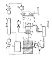
- Figure 4 is a schematic view of a liquid drop printing or recording system using a drop generator according to the present invention.
- The scale of the drawings is greatly exaggerated to help in the description. The
thin body generator 1 in Figure 1 includes a backing plate 2, a thinpiezoelectric exciter 3, a transmission block 4, aliquid chamber 5 and anozzle plate 6. The exciter includes an electrically poled polyvinylidene fluoride (PVF2) film 7 havingelectrodes AC voltage source 10 to electrically activate the film. The activated film generates acoustic oscillations at the frequency of the AC source. One example of a suitable AC signal frequency is 100 kHz. The oscillation frequency of theexciter 3 determines the drop generation rate, in this example 100 thousand drops per second. Spacers 11 between the transmission block and nozzle plate along withplates 4 and 6 define the cavity orchamber 5. - Drops are produced from liquid fed into the
chamber 5 under pressure. The liquid pressure forces a column 13 (see Figure 4) of liquid out of thegenerator 1 through anozzle 14. The column breaks up into drops 15 (see Figure 4) at some finite distance from the nozzle. The break up point remains constant as do the size and spacing of the drops due to the fixed frequency, acoustic stimulation of the liquid by exciter 3. - The
exciter 3 is preferably an electrically poled, PVF 2film of the type disclosed in European Patent Publication No. 0020182, to which the reader is referred for a more detailed explanation. The term piezoelectric, as used herein, is meant to include not only a piezoelectric response exhibited by a structure but also an electrostrictive response exhibited by a structure. Broadly, the present piezoelectric exciter is intended to define those devices that convert AC electrical energy into AC mechanical or acoustic energy. - The exciter, PVF2 film 7, including the
electrodes exciter 3 is operated at a non-resonant frequency which is contrary to prior art experience. Conventional practice is to drive an exciter at its lowest or a multiple resonant frequency because the maximum coupling of the acoustic energy to a liquid is realized at a resonant frequency. An exception to the conventional practice is the usage reported by White et al in U.S. Patent 4,032,92.8 supra. However, the disclosure of White et al is limited to a specific miniature drop modulator that is not merely thin but also very narrow. The narrowness of the structure reported by White et a makes the device unsuited for generating a plurality of streams spanning all or large portions of the width of a target, e.g. a 21.6 cm or 27.9 cm dimension of a plain paper target. - The
exciter 1 is successful as a wide, multiple nozzle drop generator for reasons that include the use of polymer exciters such as PVF2 films. The prior art teaching, as represented by White et al, suggested that only limited surface area exciters are possible. It is believed that this attitude follows from a desire to have the lowest lateral resonant mode (in the plane of the exciter) lie at frequencies well in excess of the desired opeating frequency. In hard, low attenuation materials such as piezoelectric crystals and ceramics, the lateral resonances can have dramatic effects. Furthermore, thin piezoelectric crystals and ceramics are difficult if not impossible to produce and use in large area sheets because of their brittle nature. The miniature modulator of White et al succeeds simply because of its exceptionally small scale in width as well as thickness. - The
exciter 1 also differs from the White et al exciter in other ways. One dramatic difference is thatexciter 1 employs a transmission block 4. Another dramatic difference is thatexciter 1 employs a comparatively thick backing plate 2. - Viewed as an
entity generator 1, withexciter 3 sandwiched between twothick plates 2 and 3, appears to be similar to prior art devices such as those disclosed in U.S. Patents 4,005,435 to Lindquist et al and 4,138,687 to Cha et al. In these two patents a piezoelectric crystal or ceramic is located between two thick metal blocks. One of the blocks is in contact with the liquid in an ink chamber. In these devices, the dimensions of the metal blocks or plates are comparable to the acoustic wavelengths involved. The thicknesses of the sandwich in the prior art devices are selected to set the shortest acoustic resonant frequency of the three composite layers equal to the desired drop generation rate. - In this invention, the thickness of the backing plate 2 and transmission plate or block 4 are selected such that the acoustic resonant frequency of the
composite layers 2, 3 and 4 is still well above the desired drop generation frequency. For this reason, the present drop generators are substantially different from those of the prior art. - The thickness "a" (see Figure 1) of the backing plate 2 is made large compared to that shown in Figure 3 of the White et al patent 4,032,928 wherein the thickness of a backing plate is represented as less than that of the piezoelectric crystal. The thickness "b" of the transmission block 4 is selected here to be equal to or less than that of the backing plate, a thin diaphram is disclosed in White et al rather than a transmission block.
- The transmission block chemically isolates the
exciter 3 from the liquid in thechamber 5. It also has adequate thickness for accommodating the fluid orliquid infeed conduit 16. Theinfeed pipe 16 is coupled to anexternal conduit 17 which in turn is in fluid communication with a pressurized liquid source represented by thearrow 18. - The chamber thickness "c" (see Figure 1) is very small. Specifically, it is significantly less than that of the transmission plate or nozzle plate. Its thickness is selected such that there is substantially no difference in the acoustic pressure across the dimension "c". This condition permits the generator to be characterized or analogized to a mass on a spring. The mass is the nozzle plate and the spring is the liquid in
chamber 5. The motion or displacement ofwall 20 of the transmission block due to the oscillation ofexciter 3 is imparted to thenozzle plate 6 by the liquid. The result is that the static pressure of the liquid inchamber 5 is varied by some amount at the frequency established by theAC voltage source 10. These pressure variations in turn cause drops 15 (Figure 4) to be generated at the frequency ofsource 10. - Past generators, while successful, have shown some non-uniformity from drop stream to drop stream in multiple nozzle generators. The cause of this is due, at least in part, to the interaction of the acoustic waves in the liquid chamber and the acoustic waves in the body of the generator, i.e. the walls, backing plates and the like. The thin body generators of the present invention are designed to confine the acoustic energy to a small volume of liquid, i.e. the liquid 12 in
chamber 5, made with very simple parts. - The thickness of
chamber 5 forces offensive transverse compressional acoustic wave modes to occur at frequencies far in excess of the drop generation rate. The thickness "c" ofchamber 5, according to the present concept, should be less than 5 percent of the wavelength of sound in the liquid at the drop rate. - The thickness "a" of the backing plate 2 is made as large as permissible while remaining thin in terms of percent of wavelength. The ideal is to have the
backing plate wall 21 at rest so that the total thickness changes in theexciter 3 are applied to the transmission block 4. Accordingly, the dimension "a" of a backing plate should be about 5 percent of LB, the acoustic wavelength at the drop rate in the backing plate material. Thebacking plate 21, transmission block 4 andnozzle plate 6 are composed of stainless steel, the presently preferred material. - As mentioned earlier, the transmission block thickness "b" should be equal to or less than that of "a" when both are made of the same material. Otherwise, the dimension "b" should also be equal to or less than about 5 percent of LT, the acoustic wavelength in the block 4 at the desired drop rate or range of drop rates. This condition is readily met because of the thinness of the plates.
- The dimension "d" for
nozzle plate 6 is selected to be compatible with the foregoing. The thickness "d" should be large enough to enable the nozzle plate to contain the liquid inchamber 5. It should also be thin to reduce acoustic pressure drop within thenozzle 14 formed inplate 6. - The
nozzle plate 6 may be viewed as a mass vibrating on a spring, i.e. the liquid inchamber 5. If this mass and spring system is operated at its resonant frequency, significant pressure variations are developed in the liquid. The resonant frequency is of course, selected to be near that of the range of desired drop rates. The resonant frequency f is defined by
chamber 5 andplate 6 shown in Figures 1 and 2. - From equation (1), keeping dimension "d" small is intuitively advantageous to the above objectives. However, "d" must be large enough to enable the nozzle plate to withstand the liquid pressure developed in
chamber 5. To achieve good mechanical stiffness for the nozzle plate while making the thickness "d" as small as possible, the dimensions "c" and "d" are selected to set the flexural resonance frequency of the nozzle plate near twice the drop rate. The expression for flexural resonance is
- The dimension "e" is selected by setting the value of "e" to one half the acoustic wavelength in the liquid at the drop rate. This is defined by the expression

- From equations (2) and (3) setting fflex = 2f, d is given by

- From equations (1) and (4), "c" is given by

- At the outset, the dimensions "a" and "b" for the backing and transmission plates were said to be about 5 percent of the acoustic wavelength. This is expressed for "a" in


- The foregoing discussion describes in terms of drop frequency or rate the thin drop generator of this invention. The
generator 25 of Figure 2 has its dimensions a-e selected in the same manner.Generator 25 is the presently preferred embodiment of the present invention, however, because it includes moats for isolating the acoustic energy in the region of a liquid chamber.Generator 25 also includes novel suspension means for the backing plate, transmission block and nozzle plate which act to insulate the supporting structure from the acoustic vibrations. -
Generator 25 includes: backingplate 26;pizoelectric exciter 27;transmission plate 28;liquid chamber 29; and nozzle plate 30. the nozzle plate contains a plurality of nozzles 31 that extend for asignificant distance 1. (See the isometric view in Figure 3.) Theinfeed conduit 32 is coupled to theexternal conduit 33 that couples a liquid 33 intochamber 29 from a pressurized source represented byarrow 34. - The active acoustic parts of
generator 25 are those within the elevation"e" as shown. The regions above and below the dimension "e" constitute the support structure for the generator. The active parts are held in place by thin regions or suspension means of the backing, transmission and nozzle plates identified by the dashedcircles 36 at six places in Figures 2 and 3. As best seen in Figure 3, the suspension means or regions extend thelength 1 ofgenerator 25. Each suspension region has a uniform cross-section with dimensions h and T as shown in Figure 2. The h and T dimensions are the smallest possible for the most critical element; namely, the nozzle plate 30. The like dimensions for the suspension regions on thebacking plate 26 andtransmission plate 28 are by necessity adequate. The suspension regions also define the moats. Thegenerator 25 includes upper andlower air moats lower liquid moats - The moats 37-40 extend across the width of the generator. The x, y and z orthogonal vectors of an x, y and z orthogonal coordinate system are shown in all the figures. The z axis is the direction of the drop streams and the axis along which the thicknesses "a", "b", "c" and "T" are measured. The y axis is the axis along which the heights "e" and "h" are measured. The x axis is the axis along which the plurality of nozzles 31 are arranged over a
length 1. - The
air moats backing plate 26. Their purpose is to confine the acoustic energy to the region of the backing plate within the elevation "e". Also, the air moats define the cross-sectional shape of the suspension means 36 for the backing plate. The y and z axis dimensions of all the suspension means are the same; namely, h x T which are shown in Figure 2 and explained below. The suspension means 36 for the backing plate can be located at other positions within the air moats along the z axis. In that case, eachmoat - The air moats are cut-outs from the backing plate. They contain an ambient gas such as air. Other gases or materials that have a low acoustic impedance can be used in these moats in lieu of air.
- The
liquid moats nozzle plates 28 and 30 above and below theliquid chamber 29. Thechamber 29 is itself formed from a cut-out in thetransmission block 28. The location of theboundary 35 betweenplates 28 and 30 in the regions above and belowmoats - The height "h" of the liquid moats is small enough for the liquid to be acoustically non-resonant at the drop frequency. The length of the moats along the z axis is given by the sum of the dimensions "b", "c" and "d" less two times the thickness "T" of the
suspension regions 36. The liquid moats acoustically isolate the regions of the transmission and nozzle plates above and below the moats from the acoustic energy generated by theexciter 27. (The exciter is, of couse, a PVF2 film having electrodes on its sides like theexciter 3 in Figure 1.) The liquid moats also define thesuspension regions 36 of the transmission andnozzle plates 28 and 30. - The suspension regions 36 (all six) are to allow the portion of
plates exciter 27. Thesuspension regions 36 must be strong enough, however, to retain the pressurized liquid in thechamber 29. If thesuspension regions 36 are too soft, start up and shut down of the drop streams is adversely affected. The fundamental criterion is that the retaining force on thesuspension regions 36 be less than the inertial forces on thesuspension regions 36. This is achieved by choosing the resonant frequency for thesuspension regions 36 to be below the drop generation frequency or rate by a factor of two. All sixsuspension regions 36 are made the same size which suggests that the dimension chosen are those dictated by the plate with the smallest mass: the nozzle plate. - When nozzle plate 30 is executing harmonic motion with displacement amplitude A, the inertial force per unit area along the nozzle area in the x axis is given by

- For a suspension region height "h" and thickness "T", the combined force per unit length along the x axis of the
suspension regions 36 of the nozzle plate is given by
suspension region 36. - When the
suspension regions 36 of the nozzle plate is at a resonant frequency, the forces F. and F are equal. This condition enables the following expression for f to be stated by


- The ratio of T to h is independent of frequency. To obtain a desired stiffness for the suspension regions one merely chooses an appropriate ratio for T:h. Specific values for T and h are chosen by making the assumption that the mass of the
suspension regions 36 of the nozzle plate are negligible compared to that of the portion of the nozzle plate within the acoustic region defined by elevation "e". This assumption is valid if the cross-sectonal area of thesuspension regions 36, i.e. h x T, is much smaller than the cross-sectional area of portion of the nozzle plate within the height "e", i.e. d x e. - A dimension for "h" is selected empirically for drop generators suited for printing operations. A presently preferred range for h is from about 0.5 to about 1.0 millimeters.
- Using the above equations and assumptions, a family of
drop generator 25 dimensions are available. The family of generators are scaled in size according to drop generation frequencies f. An example of a family ofgenerators 25 is given by the following Table 1. The material making up the nozzle plate is stainless steel and the liquid is water in the table.
- The drop generators of this invention are suited for ink jet printing systems of the type in Figure 4 shown by way of example. The
generator 1 of Figure 1 is employed in the system of Figure 4.Liquid columns 13 exit from a plurality of nozzles aligned along the x axis like the nozzles 31 shown in Figure 3. At the point of drop formation, a chargingelectrode tunnel 42 is positioned. The liquid 12 is electrically grounded through the steel body ofgenerator 1. A voltage coupled to a charging electrode, at and just prior to the moment of drop separation fromcolumn 13, causes a drop to assume a net charge proportional to the applied voltage. - The drops follow a
trajectory 43 toward atarget 44 to be printed. Uncharged drops, for example, fly directly to the target or a test gutter (not shown) located downstream of the target. The test gutter is used during such times such as start up and shut down of thedrop generator 1. Charged drops are deflected in the x-z plane by a steady state electrostatic field created between two deflection electrodes located on both sides of each drop stream. Only onedeflection electrode 45 is shown in Figure 4 because the other lies directly behind it. Thenozzles 14 are spaced apart by many drop diameters. The electrostatic deflection of drops in the x-z plane enables each nozzle to generate drops that address the plurality of pixels within a segment of a scan line at thetarget 45. A unique charge is assigned to each pixel within the scan line segment. Collectively, the multiple nozzles compose a full scan line or print line from the line segments addressed by each nozzle. If a drop is needed at a given pixel, the drop is charged to the level corresponding to the pixel address. If a drop is not needed or desired at the target, the drop is charged to a level that enables the drop to intersect the collection gutter 46. - Two dimensional images are printed on
target 44 in a scan line by scan line raster scanning process. The target is moved in the direction ofarrow 47 to present a fresh print line on the target at the x-z plane in which the drops fly. Thedrive wheels target 44 relative to thedrop generator 1. - The liquid from the drops collected by the gutter 46 is returned via the
conduit 50 to theliquid ink reservoir 53. Liquid is supplied under pressure togenerator 1 by the pump 54 that is coupled toconduit 55 running from the reservoir to thegenerator 1. Thedevice 56 is a filter. - The printing system of Figure 4 is operated by a
controller 57. The controller includes a microprocessor, associated memory and appropriate interface circuits. The controller receives video data at an input line 58. The controller orchestrates the operation of the various components of the system to place drops on the target at desired pixels within a two dimensional raster pattern. The controller regulates the pump 54 via the digital to analog converter (DAC) 59 and theamplifier 60. It controls theAC voltage source 10 that drives theexciter 3. The controller operates the target transport wheels via theDAC 61 andamplifier 62 coupled to themotor 63. The motor is coupled to thewheels nozzles 14. - The controller applies voltages to each charging
electrode 42 for each drop stream via the DAC's 64 and amplifiers 65. The controller includes a system clock for synchronizing the operation of the many components of the system. In addition, the controller operates the system during the start up, shut down and test procedures. - Many modifications and variations are apparent from the foregoing described method and apparatus. For example, the
generator
Claims (10)
Applications Claiming Priority (2)
| Application Number | Priority Date | Filing Date | Title |
|---|---|---|---|
| US212646 | 1980-12-03 | ||
| US06/212,646 US4370663A (en) | 1980-12-03 | 1980-12-03 | Thin body ink drop generator |
Publications (3)
| Publication Number | Publication Date |
|---|---|
| EP0053468A2 true EP0053468A2 (en) | 1982-06-09 |
| EP0053468A3 EP0053468A3 (en) | 1983-11-02 |
| EP0053468B1 EP0053468B1 (en) | 1986-01-29 |
Family
ID=22791895
Family Applications (1)
| Application Number | Title | Priority Date | Filing Date |
|---|---|---|---|
| EP81305538A Expired EP0053468B1 (en) | 1980-12-03 | 1981-11-24 | Liquid ink drop generator |
Country Status (5)
| Country | Link |
|---|---|
| US (1) | US4370663A (en) |
| EP (1) | EP0053468B1 (en) |
| JP (1) | JPS57117972A (en) |
| DE (1) | DE3173677D1 (en) |
| DK (1) | DK501381A (en) |
Cited By (3)
| Publication number | Priority date | Publication date | Assignee | Title |
|---|---|---|---|---|
| EP0145066A2 (en) * | 1983-11-26 | 1985-06-19 | Philips Patentverwaltung GmbH | Microplanar ink jet print head |
| EP0275211A2 (en) * | 1987-01-16 | 1988-07-20 | Xerox Corporation | Travelling wave droplet generator for an ink jet printer |
| EP0359974A2 (en) * | 1988-09-17 | 1990-03-28 | Haubold-Kihlberg Gmbh | Pneumatically operated driving-tool with a relief valve in the main valve |
Families Citing this family (6)
| Publication number | Priority date | Publication date | Assignee | Title |
|---|---|---|---|---|
| DE3306098A1 (en) * | 1983-02-22 | 1984-08-23 | Siemens AG, 1000 Berlin und 8000 München | PIEZOELECTRICALLY OPERATED WRITING HEAD WITH CHANNEL MATRICE |
| US4843407A (en) * | 1987-08-18 | 1989-06-27 | Burlington Industries, Inc. | Fluid distribution bar for fluid-jet printing |
| US5387760A (en) * | 1990-10-19 | 1995-02-07 | Seiko Epson Corporation | Wet recording apparatus for developing electrostatic latent image |
| US6679584B2 (en) * | 1997-07-15 | 2004-01-20 | Silverbrook Research Pty Ltd. | High volume pagewidth printing |
| GB9827262D0 (en) * | 1998-12-10 | 1999-02-03 | The Technology Parternership Plc | Switchable spray generator and method of operation |
| GB0011713D0 (en) * | 2000-05-15 | 2000-07-05 | Marconi Data Systems Inc | A continuous stream binary array ink jet print head |
Citations (5)
| Publication number | Priority date | Publication date | Assignee | Title |
|---|---|---|---|---|
| DE2455854B2 (en) * | 1974-01-10 | 1976-07-22 | International Business Machines Corp., Armonk, N.Y. (V.StA.) | DEVICE FOR GENERATING SUCCESSIVE LIQUID DROPS IN PARALLEL JETS, IN PARTICULAR FOR INKJET PRINTERS |
| DE2166927A1 (en) * | 1970-09-09 | 1976-12-16 | Clevite Corp | DEVICE FOR GENERATING A JET OF DROPS, IN PARTICULAR FOR INK DROP PENS |
| US4032928A (en) * | 1976-08-12 | 1977-06-28 | Recognition Equipment Incorporated | Wideband ink jet modulator |
| US4056742A (en) * | 1976-04-30 | 1977-11-01 | Tibbetts Industries, Inc. | Transducer having piezoelectric film arranged with alternating curvatures |
| DE2812372A1 (en) * | 1977-03-23 | 1978-09-28 | Ibm | INKJET PRINT HEAD |
Family Cites Families (3)
| Publication number | Priority date | Publication date | Assignee | Title |
|---|---|---|---|---|
| US4005435A (en) * | 1975-05-15 | 1977-01-25 | Burroughs Corporation | Liquid jet droplet generator |
| US4138687A (en) * | 1977-07-18 | 1979-02-06 | The Mead Corporation | Apparatus for producing multiple uniform fluid filaments and drops |
| US4296417A (en) * | 1979-06-04 | 1981-10-20 | Xerox Corporation | Ink jet method and apparatus using a thin film piezoelectric excitor for drop generation with spherical and cylindrical fluid chambers |
-
1980
- 1980-12-03 US US06/212,646 patent/US4370663A/en not_active Expired - Lifetime
-
1981
- 1981-11-12 DK DK501381A patent/DK501381A/en not_active Application Discontinuation
- 1981-11-20 JP JP56186788A patent/JPS57117972A/en active Pending
- 1981-11-24 DE DE8181305538T patent/DE3173677D1/en not_active Expired
- 1981-11-24 EP EP81305538A patent/EP0053468B1/en not_active Expired
Patent Citations (5)
| Publication number | Priority date | Publication date | Assignee | Title |
|---|---|---|---|---|
| DE2166927A1 (en) * | 1970-09-09 | 1976-12-16 | Clevite Corp | DEVICE FOR GENERATING A JET OF DROPS, IN PARTICULAR FOR INK DROP PENS |
| DE2455854B2 (en) * | 1974-01-10 | 1976-07-22 | International Business Machines Corp., Armonk, N.Y. (V.StA.) | DEVICE FOR GENERATING SUCCESSIVE LIQUID DROPS IN PARALLEL JETS, IN PARTICULAR FOR INKJET PRINTERS |
| US4056742A (en) * | 1976-04-30 | 1977-11-01 | Tibbetts Industries, Inc. | Transducer having piezoelectric film arranged with alternating curvatures |
| US4032928A (en) * | 1976-08-12 | 1977-06-28 | Recognition Equipment Incorporated | Wideband ink jet modulator |
| DE2812372A1 (en) * | 1977-03-23 | 1978-09-28 | Ibm | INKJET PRINT HEAD |
Cited By (6)
| Publication number | Priority date | Publication date | Assignee | Title |
|---|---|---|---|---|
| EP0145066A2 (en) * | 1983-11-26 | 1985-06-19 | Philips Patentverwaltung GmbH | Microplanar ink jet print head |
| EP0145066A3 (en) * | 1983-11-26 | 1987-01-28 | Philips Patentverwaltung Gmbh | Microplanar ink jet print head |
| EP0275211A2 (en) * | 1987-01-16 | 1988-07-20 | Xerox Corporation | Travelling wave droplet generator for an ink jet printer |
| EP0275211A3 (en) * | 1987-01-16 | 1989-12-27 | Xerox Corporation | Travelling wave droplet generator for an ink jet printer |
| EP0359974A2 (en) * | 1988-09-17 | 1990-03-28 | Haubold-Kihlberg Gmbh | Pneumatically operated driving-tool with a relief valve in the main valve |
| EP0359974A3 (en) * | 1988-09-17 | 1991-07-03 | Haubold-Kihlberg Gmbh | Pneumatically operated driving-tool with a relief valve in the main valve |
Also Published As
| Publication number | Publication date |
|---|---|
| DK501381A (en) | 1982-06-04 |
| EP0053468A3 (en) | 1983-11-02 |
| EP0053468B1 (en) | 1986-01-29 |
| US4370663A (en) | 1983-01-25 |
| DE3173677D1 (en) | 1986-03-13 |
| JPS57117972A (en) | 1982-07-22 |
Similar Documents
| Publication | Publication Date | Title |
|---|---|---|
| EP0243118B1 (en) | Spatial stabilization of standing capillary surface waves | |
| EP0243117B1 (en) | Spatially addressable capillary wave droplet ejectors | |
| EP0636477B1 (en) | Method and apparatus for producing dot size modulated ink jet printing | |
| EP0721840B1 (en) | Method and apparatus for producing dot size modulated ink jet printing | |
| EP0943436B1 (en) | Droplet generator | |
| EP0053468B1 (en) | Liquid ink drop generator | |
| US6196664B1 (en) | Ink droplet eject apparatus and method | |
| US4703330A (en) | Color ink jet drop generator using a solid acoustic cavity | |
| EP1286838B1 (en) | A continuous stream binary array ink jet print head | |
| US6206496B1 (en) | Ink jet recording head drive device and method thereof | |
| US6505920B1 (en) | Synchronously stimulated continuous ink jet head | |
| EP0624469A1 (en) | Improved drop generator utilizing damping for mode suppression | |
| JP2005280199A (en) | Liquid jet device | |
| US7500734B2 (en) | Inkjet recording head and inkjet recording device | |
| JP2001293865A (en) | Ink jet recording head and image recorder | |
| JPH01101160A (en) | Driving of on-demand ink jet head | |
| JP2690327B2 (en) | On-demand type inkjet head | |
| JPH0557891A (en) | Ink jet printing head | |
| JPH0858087A (en) | Method for driving ink jet head | |
| JPH0452143A (en) | Ink jet recorder | |
| JP2001293864A (en) | Oscillator unit and ink jet recording head | |
| EP0709194A1 (en) | Ink jet printhead | |
| JPH04187440A (en) | Ink jet recorder | |
| WO2000033972A1 (en) | Switchable spray generator and method of operation | |
| JPS59194863A (en) | Integrated ink-on-demand head |
Legal Events
| Date | Code | Title | Description |
|---|---|---|---|
| PUAI | Public reference made under article 153(3) epc to a published international application that has entered the european phase |
Free format text: ORIGINAL CODE: 0009012 |
|
| AK | Designated contracting states |
Designated state(s): DE FR GB IT |
|
| 17P | Request for examination filed |
Effective date: 19821222 |
|
| PUAL | Search report despatched |
Free format text: ORIGINAL CODE: 0009013 |
|
| AK | Designated contracting states |
Designated state(s): DE FR GB IT |
|
| GRAA | (expected) grant |
Free format text: ORIGINAL CODE: 0009210 |
|
| AK | Designated contracting states |
Designated state(s): DE FR GB IT |
|
| ET | Fr: translation filed | ||
| REF | Corresponds to: |
Ref document number: 3173677 Country of ref document: DE Date of ref document: 19860313 |
|
| ITF | It: translation for a ep patent filed |
Owner name: MODIANO & ASSOCIATI S.R.L. |
|
| PLBE | No opposition filed within time limit |
Free format text: ORIGINAL CODE: 0009261 |
|
| STAA | Information on the status of an ep patent application or granted ep patent |
Free format text: STATUS: NO OPPOSITION FILED WITHIN TIME LIMIT |
|
| 26N | No opposition filed | ||
| PGFP | Annual fee paid to national office [announced via postgrant information from national office to epo] |
Ref country code: FR Payment date: 19890911 Year of fee payment: 9 |
|
| PGFP | Annual fee paid to national office [announced via postgrant information from national office to epo] |
Ref country code: DE Payment date: 19891002 Year of fee payment: 9 |
|
| PGFP | Annual fee paid to national office [announced via postgrant information from national office to epo] |
Ref country code: GB Payment date: 19891031 Year of fee payment: 9 |
|
| ITTA | It: last paid annual fee | ||
| PG25 | Lapsed in a contracting state [announced via postgrant information from national office to epo] |
Ref country code: GB Effective date: 19901124 |
|
| GBPC | Gb: european patent ceased through non-payment of renewal fee | ||
| PG25 | Lapsed in a contracting state [announced via postgrant information from national office to epo] |
Ref country code: FR Effective date: 19910731 |
|
| PG25 | Lapsed in a contracting state [announced via postgrant information from national office to epo] |
Ref country code: DE Effective date: 19910801 |
|
| REG | Reference to a national code |
Ref country code: FR Ref legal event code: ST |