EP0053418A2 - A method for the underground gasification of coal or browncoal - Google Patents
A method for the underground gasification of coal or browncoal Download PDFInfo
- Publication number
- EP0053418A2 EP0053418A2 EP81201289A EP81201289A EP0053418A2 EP 0053418 A2 EP0053418 A2 EP 0053418A2 EP 81201289 A EP81201289 A EP 81201289A EP 81201289 A EP81201289 A EP 81201289A EP 0053418 A2 EP0053418 A2 EP 0053418A2
- Authority
- EP
- European Patent Office
- Prior art keywords
- cavity
- coal
- liquid
- gas
- boreholes
- Prior art date
- Legal status (The legal status is an assumption and is not a legal conclusion. Google has not performed a legal analysis and makes no representation as to the accuracy of the status listed.)
- Granted
Links
- 239000003245 coal Substances 0.000 title claims abstract description 39
- 238000002309 gasification Methods 0.000 title claims abstract description 21
- 238000000034 method Methods 0.000 title claims abstract description 17
- 239000003077 lignite Substances 0.000 title claims abstract description 4
- 239000007788 liquid Substances 0.000 claims abstract description 41
- 239000000945 filler Substances 0.000 claims abstract description 37
- XLYOFNOQVPJJNP-UHFFFAOYSA-N water Substances O XLYOFNOQVPJJNP-UHFFFAOYSA-N 0.000 claims abstract description 33
- 239000000463 material Substances 0.000 claims abstract description 23
- 238000002485 combustion reaction Methods 0.000 claims abstract description 19
- 239000000126 substance Substances 0.000 claims abstract description 8
- 239000007789 gas Substances 0.000 claims description 52
- 239000000725 suspension Substances 0.000 claims description 17
- QVGXLLKOCUKJST-UHFFFAOYSA-N atomic oxygen Chemical compound [O] QVGXLLKOCUKJST-UHFFFAOYSA-N 0.000 claims description 13
- 230000008021 deposition Effects 0.000 claims description 13
- 239000001301 oxygen Substances 0.000 claims description 13
- 229910052760 oxygen Inorganic materials 0.000 claims description 13
- 239000000567 combustion gas Substances 0.000 claims description 8
- 238000007254 oxidation reaction Methods 0.000 claims description 8
- 238000007599 discharging Methods 0.000 claims description 6
- 230000003647 oxidation Effects 0.000 claims description 6
- 239000002689 soil Substances 0.000 claims description 5
- 238000004891 communication Methods 0.000 claims description 2
- 239000002244 precipitate Substances 0.000 claims description 2
- 238000001556 precipitation Methods 0.000 claims description 2
- 238000005728 strengthening Methods 0.000 claims description 2
- 230000015572 biosynthetic process Effects 0.000 abstract description 2
- 230000000977 initiatory effect Effects 0.000 abstract description 2
- 238000005755 formation reaction Methods 0.000 abstract 1
- CURLTUGMZLYLDI-UHFFFAOYSA-N Carbon dioxide Chemical compound O=C=O CURLTUGMZLYLDI-UHFFFAOYSA-N 0.000 description 8
- 239000000203 mixture Substances 0.000 description 8
- 238000002474 experimental method Methods 0.000 description 6
- 239000004576 sand Substances 0.000 description 6
- 229910002092 carbon dioxide Inorganic materials 0.000 description 4
- 239000001569 carbon dioxide Substances 0.000 description 4
- 239000008187 granular material Substances 0.000 description 3
- 230000001788 irregular Effects 0.000 description 3
- 239000002002 slurry Substances 0.000 description 3
- 239000004568 cement Substances 0.000 description 2
- 238000001704 evaporation Methods 0.000 description 2
- 230000002349 favourable effect Effects 0.000 description 2
- 238000011010 flushing procedure Methods 0.000 description 2
- 239000006194 liquid suspension Substances 0.000 description 2
- VNWKTOKETHGBQD-UHFFFAOYSA-N methane Chemical compound C VNWKTOKETHGBQD-UHFFFAOYSA-N 0.000 description 2
- 239000002245 particle Substances 0.000 description 2
- 230000000063 preceeding effect Effects 0.000 description 2
- 230000001105 regulatory effect Effects 0.000 description 2
- OKTJSMMVPCPJKN-UHFFFAOYSA-N Carbon Chemical compound [C] OKTJSMMVPCPJKN-UHFFFAOYSA-N 0.000 description 1
- UGFAIRIUMAVXCW-UHFFFAOYSA-N Carbon monoxide Chemical compound [O+]#[C-] UGFAIRIUMAVXCW-UHFFFAOYSA-N 0.000 description 1
- UFHFLCQGNIYNRP-UHFFFAOYSA-N Hydrogen Chemical compound [H][H] UFHFLCQGNIYNRP-UHFFFAOYSA-N 0.000 description 1
- 239000007900 aqueous suspension Substances 0.000 description 1
- 229910052799 carbon Inorganic materials 0.000 description 1
- 229910002091 carbon monoxide Inorganic materials 0.000 description 1
- 230000001276 controlling effect Effects 0.000 description 1
- 230000003628 erosive effect Effects 0.000 description 1
- 230000008020 evaporation Effects 0.000 description 1
- 238000004880 explosion Methods 0.000 description 1
- 239000001257 hydrogen Substances 0.000 description 1
- 229910052739 hydrogen Inorganic materials 0.000 description 1
- 210000003141 lower extremity Anatomy 0.000 description 1
- 238000004519 manufacturing process Methods 0.000 description 1
- 238000003825 pressing Methods 0.000 description 1
- 230000000644 propagated effect Effects 0.000 description 1
- 238000004062 sedimentation Methods 0.000 description 1
- 239000007787 solid Substances 0.000 description 1
Images
Classifications
-
- E—FIXED CONSTRUCTIONS
- E21—EARTH OR ROCK DRILLING; MINING
- E21B—EARTH OR ROCK DRILLING; OBTAINING OIL, GAS, WATER, SOLUBLE OR MELTABLE MATERIALS OR A SLURRY OF MINERALS FROM WELLS
- E21B43/00—Methods or apparatus for obtaining oil, gas, water, soluble or meltable materials or a slurry of minerals from wells
- E21B43/295—Gasification of minerals, e.g. for producing mixtures of combustible gases
-
- E—FIXED CONSTRUCTIONS
- E21—EARTH OR ROCK DRILLING; MINING
- E21B—EARTH OR ROCK DRILLING; OBTAINING OIL, GAS, WATER, SOLUBLE OR MELTABLE MATERIALS OR A SLURRY OF MINERALS FROM WELLS
- E21B43/00—Methods or apparatus for obtaining oil, gas, water, soluble or meltable materials or a slurry of minerals from wells
- E21B43/16—Enhanced recovery methods for obtaining hydrocarbons
- E21B43/24—Enhanced recovery methods for obtaining hydrocarbons using heat, e.g. steam injection
- E21B43/243—Combustion in situ
- E21B43/247—Combustion in situ in association with fracturing processes or crevice forming processes
-
- E—FIXED CONSTRUCTIONS
- E21—EARTH OR ROCK DRILLING; MINING
- E21B—EARTH OR ROCK DRILLING; OBTAINING OIL, GAS, WATER, SOLUBLE OR MELTABLE MATERIALS OR A SLURRY OF MINERALS FROM WELLS
- E21B43/00—Methods or apparatus for obtaining oil, gas, water, soluble or meltable materials or a slurry of minerals from wells
- E21B43/25—Methods for stimulating production
- E21B43/26—Methods for stimulating production by forming crevices or fractures
- E21B43/267—Methods for stimulating production by forming crevices or fractures reinforcing fractures by propping
-
- E—FIXED CONSTRUCTIONS
- E21—EARTH OR ROCK DRILLING; MINING
- E21F—SAFETY DEVICES, TRANSPORT, FILLING-UP, RESCUE, VENTILATION, OR DRAINING IN OR OF MINES OR TUNNELS
- E21F15/00—Methods or devices for placing filling-up materials in underground workings
-
- Y—GENERAL TAGGING OF NEW TECHNOLOGICAL DEVELOPMENTS; GENERAL TAGGING OF CROSS-SECTIONAL TECHNOLOGIES SPANNING OVER SEVERAL SECTIONS OF THE IPC; TECHNICAL SUBJECTS COVERED BY FORMER USPC CROSS-REFERENCE ART COLLECTIONS [XRACs] AND DIGESTS
- Y10—TECHNICAL SUBJECTS COVERED BY FORMER USPC
- Y10S—TECHNICAL SUBJECTS COVERED BY FORMER USPC CROSS-REFERENCE ART COLLECTIONS [XRACs] AND DIGESTS
- Y10S48/00—Gas: heating and illuminating
- Y10S48/06—Underground gasification of coal
Definitions
- the invention relates to a method for the underground gasification of coal or browncoal in an inclined coal layer, in which two boreholes are drilled from the soil surface into the coal layer, which boreholes are continued downwards in said layer with the slope of said layer, and are interconnected at their lower ends, after which the coal can be ignited, and, furthermore, by supplying an oxygen containing gas through one of the boreholes and discharging the combustion gases through the other borehole, the combustion front will be propagated upwards through the coal layer, and care is taken that the boreholes remain in communication with the cavity behind the combustion front, which cavity is, moreover, intermittently filled with a filler which is supplied through one of the boreholes.
- the filler serves to support the upper layer and to prevent its collapse, and, on the other hand, to ensure that the oxygen containing gas flow will contact the burning coal as efficiently as possible.
- a part of this gas flow will flow off directly towards the other borehole, and will, then, be lost for the combustion, and,moreover, the presence of oxygen containing gas in the produced combustion gases can be dangerous. Therefore a not too wide passage above the filler should be maintained in which the gas flow is turbulent, so that an optimal use of the oxygen is made possible.
- the invention is based on the insight obtained from experiments with models, during which it has appeared that the deposition from a suspension of the grains used for filling begins when entering the cavity, where the flow velocity of the suspension is sharply reduced, and, as soon as the passage is locally narrowed, a break-through will take place leading to a deposition beyond the original deposition, which break-through will move upwards to near the coal front, all this in such a manner that, eventually, the whole cavity is filled, with the exception of a relatively narrow passage having such dimensions that an equilibrium between the deposition from the suspension and the dragging along with the suspension is obtained. It has, then, also appeared that this deposition can be controlled by a suitable choice of, inter alia, the concentration of the suspension and its flow velocity.
- the method of the invention is, therefore, characterised in that the filler material is suspended in a carrier substance, which suspension is led through the boreholes and the cavity, and this in such a concentration and with such a flow velocity that the filler material, at the reduction of the flow velocity when entering the cavity, will precipitate from the suspension, and the suspension flow is continued until the cavity has been completely filled with the filler material, with the exception of a narrow channel at the upper side of this cavity near the coal front, having a width which is determined by the flow velocity in that region at which an equilibrium between precipitation and dragging along of the filler material is reached.
- the filler material is suspended in a liquid, in particular water
- the liquid is to be removed from the channel after filling and before the gasification can be restarted again, which can be done by passing through a gas, in particular air.
- the intergranular spaces of a filling thus obtained are filled by the suspension liquid.
- the presence of this liquid near the hot gasification front can, however, be disadvantageous, since the water will evaporate at the surface so that the gas composition may be changed, and, moreover, much heat will be withdrawn from the gasification front.
- a filler which is considerably mixed with a liquid will behave as a liquid which, then, cannot sufficiently withstand the ground pressure, and will, therefore, be pressed away sometimes by the ground pressure, so that the gasification channel may be closed thereby.
- the filler should at least partly be,stripped of the suspension liquid.
- this can be done by lowering an inner tube in one of the boreholes, the lower ends of this tube and of the borehole in question extending to different depths, and, thereafter, a pressurised gas is supplied to the cavity through the inner tube or through the annular passage surrounding this tube, the other borehole being closed, or through the other borehole, said inner tube or said surrounding passage then being closed, and as a consequence thereof a liquid column will be pressed upwards in the not-closed passage, the height of said column corresponding to the gas pressure, reduced, as the case may be, with the pressure prevailing above said liquid column.
- the liquid in the filler can be pressed away to a desired level which cannot be situated deeper than the opening of the passage in which the liquid column has been pressed away.
- the liquid level can be accurately adjusted. If water continues to flow in from the surroundings, a suitable choice of the pressure will ensure that the liquid column will extend up to the soil surface, and there the water can flow off then continuously, and by using a suitable throttle a counter-pressure can be maintained if necessary.
- the passage. of the borehole provided with an inner tube not used for pressing upwards the water column can, furthermore, be used for supplying the gas required for the combustion, or for discharging the produced combustion gases, and it should be ensured of course that these gases remain under the above-mentioned pressure, and suitable throttle means in the passages used for gas discharge can be used to this end.
- the granular material can also be mixed with a gas which is put under such a high pressure that the viscosity and density thereof sufficiently increase for obtaining the flow conditions required for the desired deposition of filler material. In that case no suspension liquid is to be expelled from the filler.
- a gas which is put under such a high pressure that the viscosity and density thereof sufficiently increase for obtaining the flow conditions required for the desired deposition of filler material. In that case no suspension liquid is to be expelled from the filler.
- water which possibly flows in from the surroundings can, of course, be kept away from the gasification front again.
- the eventually obtained channel will be too narrow for the flow conditions desired for filling. From experiments it has appeared that such a channel can be enlarged in a controlled manner by leading through a liquid, e.g. the pure carrier liquid, mixed or not with a gas. From experiments relationships between the gas velocity, the slope of the coal layer, the grain size and the density of the filler material, the character of the liquid, and the obtained passage cross-section have been deduced, enabling a sufficiently accurate control of the dimensions of the channel.
- a liquid e.g. the pure carrier liquid
- Fig. 1 two boreholes 1 and 2 are shown which, as described in the prior NL patent application 7710 184, extend in the direction of a coal layer 3, and can approach one another in the downward direction. It is assumed here that the coal layer 3 has been burned away to form a straight coal front 4, the underlying cavity 5 having been filled before by means of a filler 6 up to 7. As described in said prior patent application, a straight profile of the coal front 4 can be obtained by filling the initially formed cavity, which can have an irregular shape, with a heavy slurry or a solidifying or hardening mass such as cement, so that a straight filling surface is obtained which will remain straight also at later fillings. Since, initially, the bores 1 and 2 are situated very closely to one another and the cavity is accordingly small, filling it with such a mass will proceed without difficulties.
- the filling 6 consists, for instance, of sand or similar granular material.
- the cavity 5 As soon as the cavity 5 has become so large by burning away the coal layer 3 that the air or other oxygen containing gas supplied, for instance, through the borehole 1 begins to flow in a substantially laminar manner, and will, then, no longer completely contact the combustion region, the cavity 5 is to be filled again. The combustion is, then, to be interrupted.
- For filling the cavity 5 use is made of the boreholes 1 and 2, communicating with the cavity 5 by means of ports 8 and 9 resp. Ports situated at a lower level,possibly used during the preceeding gasification steps, can be temporarily closed by means of suitable inner tubes, as far as said ports still communicate with the cavity.
- additional ports 8 and 9 have to be made of course. The manner in which this is done is known, so that no further description thereof is required.
- the port 9' can, for instance, be the discharge port for the combustion gases used during the preceeding combustion step, and, again, as indicated above, a suitable tubing can be used for temporarily closing specific ports.
- the channel 11 thus obtained can, sometimes, be too narrow, i.e. will have a too large flow resistance, for obtaining an efficient gasification.
- the sedimentation of the granular filler material cannot always be controlled in such a manner that a wider channel is obtained.
- the channel 11 present at the end of the filling operation can be flushed with a suitable liquid, i.e.. generally water.
- the present liquid is to be expelled from the channel and the boreholes, which can be done with the aid of a pressurised gas.
- the filling 6, extending up to the channel 11, consists of sand grains or the like, and the interstices between the grains are filled with a liquid, i.e. generally water.
- a liquid i.e. generally water.
- a disadvantage is that such a filling can behave as quicksand, and may be pressed away by the ground pressure acting on the surfaces 10, instead of taking up said pressure.
- Another disadvantage is that, when water is flowing inward from the surrounding ground layers, the channel will get filled so that the gasification becomes impossible. Even if this does not take place, the presence of water in the filling can be harmful, since the water will absorb relatively much heat, and will change the composition of the gas when evaporating. It is, therefore, often advisable to remove the water at least partially from the filling.
- an inner tube 13 is arranged in one of the boreholes, in this case the discharge borehole 2, said tube extending to the eventually desired water level 14.
- the interspace 15 between the tube 13 and the wall of the borehole 2 is closed at 16 above the soil surface, and communicates, by means of a regulating valve 17, with a discharge tube 18. If, now, gas pressure is applied to the borehole 1 while the valve 17 is closed, the tube 13 will be filled with water until the length of the water column corresponds to the gas pressure. If the gas pressure is higher than corresponds to the length of the tube 13, water will flow from the tube 13 at the upper end until the water in the filling has reached the level 14.
- the tasks of the tube 13 and the interspace 15 can be interchanged, and it is also,possible to close the borehole 1,and to apply the gas pressure through that part of the borehole 2 which is not used for the water column.
- the borehole 1 can then be used for discharging the produced combustion gas, and this hole can be provided with an adjustable valve to that end.
- this upper layer can be filled in one or more additional operations with a solidifying substance or with a substance mutually adhering the grains of the filler material, thus obtaining a surface which is insensitive for gas flows, so that no grains will be dragged away therefrom by the gas flow anymore, and this surface will remain straight under all circumstances. Furthermore no erosion will occur in the discharge borehole, and, moreover, evaporation of water from the underlying layers through the surface will be counteracted. As soon as the surface has been sufficiently sealed in this manner, the water level in the underlying layers can be raised if necessary.
- Fig. 4A it is indicated how the gasification takes place.
- the carbon dioxide produced will be reduced again thereafter to carbon monoxide by contact with the coal in the region 20, and the produced gases flow off through the borehole 2.
- the oxidation region 29 moves onward towards the discharge hole 2, the reduction region 20 will become shorter accordingly. If, however, this region becomes too short, the reduction will become insufficient, so that the discharged gas will contain more and more carbon dioxide, and also the temperature of the gas will become higher which can be harmful for the tubings present in the borehole 2.
Landscapes
- Engineering & Computer Science (AREA)
- Mining & Mineral Resources (AREA)
- Life Sciences & Earth Sciences (AREA)
- Geology (AREA)
- General Life Sciences & Earth Sciences (AREA)
- Geochemistry & Mineralogy (AREA)
- Physics & Mathematics (AREA)
- Environmental & Geological Engineering (AREA)
- Fluid Mechanics (AREA)
- Filling Or Discharging Of Gas Storage Vessels (AREA)
Abstract
Description
- The invention relates to a method for the underground gasification of coal or browncoal in an inclined coal layer, in which two boreholes are drilled from the soil surface into the coal layer, which boreholes are continued downwards in said layer with the slope of said layer, and are interconnected at their lower ends, after which the coal can be ignited, and, furthermore, by supplying an oxygen containing gas through one of the boreholes and discharging the combustion gases through the other borehole, the combustion front will be propagated upwards through the coal layer, and care is taken that the boreholes remain in communication with the cavity behind the combustion front, which cavity is, moreover, intermittently filled with a filler which is supplied through one of the boreholes.
- Such a method has been described in the prior NL patent application 7710184 of the same applicant. In particular the boreholes, at least near their lower extremities, converge towards one another, so as to facilitate the formation of the connection between both boreholes required for initiating the gasification, and by the upward divergence of these boreholes the gasification front will obtain a length which is sufficient for an economic production.
- The filler serves to support the upper layer and to prevent its collapse, and, on the other hand, to ensure that the oxygen containing gas flow will contact the burning coal as efficiently as possible. In the case of a too wide passage, a part of this gas flow will flow off directly towards the other borehole, and will, then, be lost for the combustion, and,moreover, the presence of oxygen containing gas in the produced combustion gases can be dangerous. Therefore a not too wide passage above the filler should be maintained in which the gas flow is turbulent, so that an optimal use of the oxygen is made possible.
- It is possible to use, for filling, a thick slurry of a hardening material such as cement, but, apart from the cost, this has the draw-back that in the cavity solid particles will separate too quickly from the slurry,and/or the hardenable material solidifies too early at the prevailing temperatures. This will lead in both instances to obstruction of the cavity and an insufficient filling thereof, in particular as soon as said cavity has obtained a certain extension. A consequence of this insufficient and non-uniform filling will be that collapses can no longer be avoided, and that, furthermore, the gas flow will insufficiently come into contact with the coal, so that the composition of the gas will become poor and unstable accordingly, and, because of the presence of oxygen in the gas mixture, an explosion hazard near or in the discharge hole will arise. Moreover a consequence of a non-uniform filling will be that the combustion front obtains an irregular shape, so that filling the cavity further will become still more difficult.
- Although it has been contemplated to fill the cavity with a granular material, e.g. sand, which is led into the cavity in a gas or liquid flow through the borehole, this has been considered to be impracticable until now, since it was thought that it would not be possible to fill the cavity in this manner in a sufficient degree, i.a. because of an irregular deposition, dragging away of already deposited particles, the possibility of obstruction near the supply hole etc., and, furthermore, it was assumed that such a manner of filling would be completely uncontrollable, so that the uniform filling required for a straight combustion front would never be obtained.
- The invention is based on the insight obtained from experiments with models, during which it has appeared that the deposition from a suspension of the grains used for filling begins when entering the cavity, where the flow velocity of the suspension is sharply reduced, and, as soon as the passage is locally narrowed, a break-through will take place leading to a deposition beyond the original deposition, which break-through will move upwards to near the coal front, all this in such a manner that, eventually, the whole cavity is filled, with the exception of a relatively narrow passage having such dimensions that an equilibrium between the deposition from the suspension and the dragging along with the suspension is obtained. It has, then, also appeared that this deposition can be controlled by a suitable choice of, inter alia, the concentration of the suspension and its flow velocity.
- The method of the invention is, therefore, characterised in that the filler material is suspended in a carrier substance, which suspension is led through the boreholes and the cavity, and this in such a concentration and with such a flow velocity that the filler material, at the reduction of the flow velocity when entering the cavity, will precipitate from the suspension, and the suspension flow is continued until the cavity has been completely filled with the filler material, with the exception of a narrow channel at the upper side of this cavity near the coal front, having a width which is determined by the flow velocity in that region at which an equilibrium between precipitation and dragging along of the filler material is reached.
- If the filler material is suspended in a liquid, in particular water, the liquid is to be removed from the channel after filling and before the gasification can be restarted again, which can be done by passing through a gas, in particular air.
- The intergranular spaces of a filling thus obtained are filled by the suspension liquid. The presence of this liquid near the hot gasification front can, however, be disadvantageous, since the water will evaporate at the surface so that the gas composition may be changed, and, moreover, much heat will be withdrawn from the gasification front. Furthermore a filler which is considerably mixed with a liquid will behave as a liquid which, then, cannot sufficiently withstand the ground pressure, and will, therefore, be pressed away sometimes by the ground pressure, so that the gasification channel may be closed thereby. Sometimes, therefore, the filler should at least partly be,stripped of the suspension liquid. According to the invention this can be done by lowering an inner tube in one of the boreholes, the lower ends of this tube and of the borehole in question extending to different depths, and, thereafter, a pressurised gas is supplied to the cavity through the inner tube or through the annular passage surrounding this tube, the other borehole being closed, or through the other borehole, said inner tube or said surrounding passage then being closed, and as a consequence thereof a liquid column will be pressed upwards in the not-closed passage, the height of said column corresponding to the gas pressure, reduced, as the case may be, with the pressure prevailing above said liquid column. In this manner the liquid in the filler can be pressed away to a desired level which cannot be situated deeper than the opening of the passage in which the liquid column has been pressed away. By varying the pressure, the length of the inner tube and/or the pressure above the liquid pressed upwards, the liquid level can be accurately adjusted. If water continues to flow in from the surroundings, a suitable choice of the pressure will ensure that the liquid column will extend up to the soil surface, and there the water can flow off then continuously, and by using a suitable throttle a counter-pressure can be maintained if necessary. The passage. of the borehole provided with an inner tube not used for pressing upwards the water column can, furthermore, be used for supplying the gas required for the combustion, or for discharging the produced combustion gases, and it should be ensured of course that these gases remain under the above-mentioned pressure, and suitable throttle means in the passages used for gas discharge can be used to this end.
- Instead of using a liquid suspension, the granular material can also be mixed with a gas which is put under such a high pressure that the viscosity and density thereof sufficiently increase for obtaining the flow conditions required for the desired deposition of filler material. In that case no suspension liquid is to be expelled from the filler. By maintaining the pressure, water which possibly flows in from the surroundings can, of course, be kept away from the gasification front again.
- In some instances the eventually obtained channel will be too narrow for the flow conditions desired for filling. From experiments it has appeared that such a channel can be enlarged in a controlled manner by leading through a liquid, e.g. the pure carrier liquid, mixed or not with a gas. From experiments relationships between the gas velocity, the slope of the coal layer, the grain size and the density of the filler material, the character of the liquid, and the obtained passage cross-section have been deduced, enabling a sufficiently accurate control of the dimensions of the channel.
- Sometimes it can be advantageous to introduce,into the upper layer of the filler stripped of the liquid,a substance for strengthening or hardening said filler.
- Finally it can be favourable to reverse the flow sense of the oxygen containing gas as soon as the combustion region is approaching the discharge borehole, so that, then, the last part of the coal layer will act as the oxydation region, and the original oxydation region as the reduction region, so as to maintain a constant gas composition until the end, and to avoid a too high temperature near the borehole which, initially, acted as the gas discharge.
- The invention will be elucidated below in more detail by reference to a drawing, showing in:
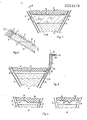
- Figs. 1 and 2 two cross-sections of a coal layer and the adjacent cavity according to line I-I of Fig. 2 or II-II of Fig. 1 reap.;
- Fig. 3 a corresponding cross-section with a completely filled cavity, and with means for removing water therefrom; and
- Figs. 4A and B two simplified cross-sections corresponding to a portion of Fig. 1 for elucidating the progression of the combustion front.
- In Fig. 1 two boreholes 1 and 2 are shown which, as described in the prior NL patent application 7710 184, extend in the direction of a coal layer 3, and can approach one another in the downward direction. It is assumed here that the coal layer 3 has been burned away to form a straight coal front 4, the
underlying cavity 5 having been filled before by means of afiller 6 up to 7. As described in said prior patent application, a straight profile of the coal front 4 can be obtained by filling the initially formed cavity, which can have an irregular shape, with a heavy slurry or a solidifying or hardening mass such as cement, so that a straight filling surface is obtained which will remain straight also at later fillings. Since, initially, the bores 1 and 2 are situated very closely to one another and the cavity is accordingly small, filling it with such a mass will proceed without difficulties. - The
filling 6 according to the invention consists, for instance, of sand or similar granular material. As soon as thecavity 5 has become so large by burning away the coal layer 3 that the air or other oxygen containing gas supplied, for instance, through the borehole 1 begins to flow in a substantially laminar manner, and will, then, no longer completely contact the combustion region, thecavity 5 is to be filled again. The combustion is, then, to be interrupted. For filling thecavity 5 use is made of the boreholes 1 and 2, communicating with thecavity 5 by means ofports 8 and 9 resp. Ports situated at a lower level,possibly used during the preceeding gasification steps, can be temporarily closed by means of suitable inner tubes, as far as said ports still communicate with the cavity. During the progression of the coal front 4additional ports 8 and 9 have to be made of course. The manner in which this is done is known, so that no further description thereof is required. - If, for instance, a sand-water suspension is supplied through the borehole 1, the flow velocity thereof will sharply decrease after leaving the port 8, so that deposition of sand will start immediately behind said port. The water fills the
space 5 and can flow off through theother port 9. Because of the deposition of sand the passage is gradually narrowed, which will lead to an increasing flow velocity and, eventually, to a break-through which, because of the upward slope of theboundary walls 10 ofspace 5, starts to revolve upwards, which will, eventually, lead to apassage 11 situated against the coal front 4. The boundary of the deposition in successive steps is schematically indicated at 12 in Fig. 1, and a break-through will occur again and again which moves upwards so that, eventually, acontinuous channel 11 extending between theports 8 and 9 is obtained. A small space 5' will remain free, unless the discharge can take place through a lower port 9', and then thechannel 11 will extend downwards along the boundary of the borehole 2 until the port 9' has been reached. The port 9' can, for instance, be the discharge port for the combustion gases used during the preceeding combustion step, and, again, as indicated above, a suitable tubing can be used for temporarily closing specific ports. - This manner of sand deposition has been ascertained by means of model experiments, in which scale factors have been taken into account. Thereby relationships between the concentration of the suspension, the grain size of the filler material, the density of the grains and the carrier, and the flow velocity of the suspension, have been determined, which, taking into account the scale factors, can be used for controlling the filling of an
underground cavity 5. - When supplying an oxygen containing gas and discharging the produced combustion gases, the
channel 11 thus obtained can, sometimes, be too narrow, i.e. will have a too large flow resistance, for obtaining an efficient gasification. The sedimentation of the granular filler material cannot always be controlled in such a manner that a wider channel is obtained. In that case, now, thechannel 11 present at the end of the filling operation can be flushed with a suitable liquid, i.e.. generally water. From model experiments relationships have-been derived indicating the relation between the grain size and the density of the filling, the flow velocity, the density and the character of the liquid flow, the slope of the coal layer and the obtained channel cross-section, so that the desired channel cross-section can be adjusted without difficulty by a corresponding choice of the liquid flow velocity. Also the viscosity of the liquid is important in this respect. Therefore it can sometimes be favourable to use, instead of a flushing liquid, a mixture of a gas and a liquid, in particular air and water. - After forming the
channel 11 and, as the case may be, widening the latter by means of a flushing liquid, the present liquid is to be expelled from the channel and the boreholes, which can be done with the aid of a pressurised gas. - The
filling 6, extending up to thechannel 11, consists of sand grains or the like, and the interstices between the grains are filled with a liquid, i.e. generally water. A disadvantage is that such a filling can behave as quicksand, and may be pressed away by the ground pressure acting on thesurfaces 10, instead of taking up said pressure. Another disadvantage is that, when water is flowing inward from the surrounding ground layers, the channel will get filled so that the gasification becomes impossible. Even if this does not take place, the presence of water in the filling can be harmful, since the water will absorb relatively much heat, and will change the composition of the gas when evaporating. It is, therefore, often advisable to remove the water at least partially from the filling. - This can, for instance, be done in the manner shown in Fig. 3. Thereto an
inner tube 13 is arranged in one of the boreholes, in this case the discharge borehole 2, said tube extending to the eventually desired water level 14. The interspace 15 between thetube 13 and the wall of the borehole 2 is closed at 16 above the soil surface, and communicates, by means of a regulatingvalve 17, with adischarge tube 18. If, now, gas pressure is applied to the borehole 1 while thevalve 17 is closed, thetube 13 will be filled with water until the length of the water column corresponds to the gas pressure. If the gas pressure is higher than corresponds to the length of thetube 13, water will flow from thetube 13 at the upper end until the water in the filling has reached the level 14. Furthermore it is possible to apply a counter-pressure to thetube 13, or to provide the latter with a regulating valve or throttle so that, then, a higher pressure than corresponds to the water column will be obtained. This can be useful for preventing that, upon reaching the level 14, substantial amounts of gas will escape through the water column. When performing the gasification under this pressure, which can be controlled by adjusting thevalve 17 through which the produced gas escapes, the filling will remain dry as low as the adjusted level. When water is flowing in from the surroundings, it can flow off through thetube 13, and the liquid level remains maintained at the desired level by adjusting the pressure and, as the case may be, the counter-pressure. - Of course the tasks of the
tube 13 and the interspace 15 can be interchanged, and it is also,possible to close the borehole 1,and to apply the gas pressure through that part of the borehole 2 which is not used for the water column. The borehole 1 can then be used for discharging the produced combustion gas, and this hole can be provided with an adjustable valve to that end. - As soon as the upper layer of the filling 6 is stripped of water, this upper layer can be filled in one or more additional operations with a solidifying substance or with a substance mutually adhering the grains of the filler material, thus obtaining a surface which is insensitive for gas flows, so that no grains will be dragged away therefrom by the gas flow anymore, and this surface will remain straight under all circumstances. Furthermore no erosion will occur in the discharge borehole, and, moreover, evaporation of water from the underlying layers through the surface will be counteracted. As soon as the surface has been sufficiently sealed in this manner, the water level in the underlying layers can be raised if necessary.
- Instead of using a liquid suspension for filling the
cavity 5 with thefiller 6, sometimes use can be made of a gas which is put under such a high pressure that its viscosity and density become sufficiently high -for obtaining the desired flow and deposition behaviour. The advantage thereof is that, afterwards, no liquid is to be expelled from the formedchannel 11, and the pressure can be chosen so that water possibly flowing in from the surroundings will be kept away from thechannel 11. In this manner the gasification can be initiated more quickly, in particular when an oxygen containing gas is used for introducing the filler material. - In Fig. 4A it is indicated how the gasification takes place. The oxygen containing gas supplied through the borehole 1, e.g. air mixed or not with water or steam, maintains the combustion in the coal layer 3, and oxidation of the coal will take place in a
region 19 where the carbon is burned to carbon dioxide, and in the presence of water vapour also hydrogen and/or methane can be produced. The carbon dioxide produced will be reduced again thereafter to carbon monoxide by contact with the coal in theregion 20, and the produced gases flow off through the borehole 2. As, however, the oxidation region 29 moves onward towards the discharge hole 2, thereduction region 20 will become shorter accordingly. If, however, this region becomes too short, the reduction will become insufficient, so that the discharged gas will contain more and more carbon dioxide, and also the temperature of the gas will become higher which can be harmful for the tubings present in the borehole 2. - In order to remove this disadvantage, the gas flow is reversed in the manner of Fig. 4B as soon as the
reduction region 20 would become too short, which can be ascertained by determining the carbon dioxide percentage. This means that, now, theoriginal reduction region 20 becomes the oxidation region, as indicated at 20', and the new coal front 4' formed behind theoriginal oxidation region 19 will act as the reduction region. In this manner the whole coal front can be burned away without changes in the composition of the gas and without the temperature thereof becoming too high. If, in the manner of Fig. 3, the gasification takes place under a high pressure, both boreholes 1 and 2 should, of course, be provided with suitable valves enabling to maintain the desired pressure also when reversing the sense of flow. Reversing the flow sense makes only sense if, in the manner of the invention, a substantiallyuniform channel 11 is formed above the filling 6, in which, along the total length, comparable flow conditions are present. - In the manner described above it becomes possible now to obtain an efficient gasification of underground coal layers with a good yield, and the composition of the gas can always be maintained at an optimal value. The relationships derived from model experiments allow to obtain, under all circumstances, an adapted cross-section of the
channel 11.
Claims (12)
Applications Claiming Priority (2)
| Application Number | Priority Date | Filing Date | Title |
|---|---|---|---|
| NL8006485A NL8006485A (en) | 1980-11-28 | 1980-11-28 | METHOD FOR UNDERGROUND GASIFICATION OF STONE OR BROWN COAL |
| NL8006485 | 1980-11-28 |
Publications (3)
| Publication Number | Publication Date |
|---|---|
| EP0053418A2 true EP0053418A2 (en) | 1982-06-09 |
| EP0053418A3 EP0053418A3 (en) | 1982-08-11 |
| EP0053418B1 EP0053418B1 (en) | 1985-04-03 |
Family
ID=19836258
Family Applications (1)
| Application Number | Title | Priority Date | Filing Date |
|---|---|---|---|
| EP81201289A Expired EP0053418B1 (en) | 1980-11-28 | 1981-11-20 | A method for the underground gasification of coal or browncoal |
Country Status (4)
| Country | Link |
|---|---|
| US (1) | US4441554A (en) |
| EP (1) | EP0053418B1 (en) |
| DE (1) | DE3169740D1 (en) |
| NL (1) | NL8006485A (en) |
Cited By (6)
| Publication number | Priority date | Publication date | Assignee | Title |
|---|---|---|---|---|
| EP0089085A1 (en) * | 1982-03-11 | 1983-09-21 | Arnold Willem Josephus Prof.Ir. Grupping | A method for the underground gasification of coal or browncoal |
| WO1991013236A1 (en) * | 1990-02-22 | 1991-09-05 | Grupping Arnold W | Method and system for underground gasification of coal or browncoal |
| CN103244178A (en) * | 2013-05-20 | 2013-08-14 | 中国矿业大学(北京) | Method for controlling diffusion and migration of underground gasification residual pollutants |
| WO2015070297A1 (en) * | 2013-11-12 | 2015-05-21 | Kovachki Hristo Atanasov | Method and device for single well underground gasification of fossil fuels |
| CN107218080A (en) * | 2017-06-28 | 2017-09-29 | 中建市政工程有限公司 | Underground water multi-stage filtering and draining system for deep and long-distance water-rich tunnel and construction method |
| CN113882895A (en) * | 2021-11-04 | 2022-01-04 | 安徽理工大学 | Strip filling coal underground gasification mining method |
Families Citing this family (5)
| Publication number | Priority date | Publication date | Assignee | Title |
|---|---|---|---|---|
| SU925094A1 (en) * | 1980-02-21 | 1988-08-15 | Всесоюзный Научно-Исследовательский Институт Использования Газа В Народном Хозяйстве И Подземного Хранения Нефти,Нефтепродуктов И Сжиженных Газов | Method of underground gasification of coal |
| BE901892A (en) * | 1985-03-07 | 1985-07-01 | Institution Pour Le Dev De La | NEW PROCESS FOR CONTROLLED RETRACTION OF THE GAS-INJECTING INJECTION POINT IN SUBTERRANEAN COAL GASIFICATION SITES. |
| CN101641496A (en) * | 2007-03-28 | 2010-02-03 | 国际壳牌研究有限公司 | Method of interconnecting subterranean boreholes |
| US8596356B2 (en) * | 2010-10-28 | 2013-12-03 | Baker Hughes Incorporated | Method of producing synthesis gas by the underground gasification of coal from a coal seam |
| CN109025951B (en) * | 2018-10-19 | 2024-01-02 | 国氢能源科技有限公司 | Underground gasifier type and building and gasification method |
Family Cites Families (15)
| Publication number | Priority date | Publication date | Assignee | Title |
|---|---|---|---|---|
| US2710232A (en) * | 1950-06-14 | 1955-06-07 | Lawrence D Schmidt | Method for filling cavities with granular solids |
| FR1053378A (en) * | 1951-04-09 | 1954-02-02 | Nat Res Dev | Improvements in underground coal gasification |
| GB716620A (en) * | 1951-08-30 | 1954-10-13 | Mini Of Fuel And Power | Improvements relating to the underground gasification of coal |
| DE1021312B (en) * | 1955-10-05 | 1957-12-27 | Hueser & Weber K G | Process for preventing dust generation in mining operations |
| US2994375A (en) * | 1957-12-23 | 1961-08-01 | Phillips Petroleum Co | Recovery of hydrocarbons by in situ combustion |
| US3331438A (en) * | 1964-09-30 | 1967-07-18 | Mobil Oil Corp | Method for in situ retorting of oil shale employing artificial barriers |
| US3440824A (en) * | 1967-05-16 | 1969-04-29 | Thomas J Doolin | Method and apparatus for backfilling and underpinning an underground coal or ore mine |
| US3566967A (en) * | 1969-06-19 | 1971-03-02 | Pan American Petroleum Corp | Thermal plugging with silicate solutions |
| SU572102A1 (en) * | 1974-12-27 | 1988-08-23 | Всесоюзный Научно-Исследовательский Институт Использования Газа В Народном Хозяйстве,Подземного Хранения Нефти,Нефтепродуктов И Сжиженных Газов | Method of working through coal channels |
| SU710245A1 (en) * | 1975-04-02 | 1988-08-23 | Всесоюзный Научно-Исследовательский Институт Использования Газа В Народном Хозяйстве,Подземного Хранения Нефти,Нефтепродуктов И Сжиженных Газов | Method of underground gasification of coal |
| US3999607A (en) * | 1976-01-22 | 1976-12-28 | Exxon Research And Engineering Company | Recovery of hydrocarbons from coal |
| US4095650A (en) * | 1977-08-10 | 1978-06-20 | The United States Of America As Represented By The United States Department Of Energy | Method for increasing the calorific value of gas produced by the in situ combustion of coal |
| NL181941C (en) * | 1977-09-16 | 1987-12-01 | Ir Arnold Willem Josephus Grup | METHOD FOR UNDERGROUND GASULATION OF COAL OR BROWN. |
| DE2846832B1 (en) * | 1978-10-27 | 1980-02-07 | Hoechst Ag | Trace element fertilizer pastes and process for their preparation |
| US4231617A (en) * | 1978-12-14 | 1980-11-04 | Gulf Oil Corporation | Consolidation of in-situ retort |
-
1980
- 1980-11-28 NL NL8006485A patent/NL8006485A/en not_active Application Discontinuation
-
1981
- 1981-11-18 US US06/322,476 patent/US4441554A/en not_active Expired - Fee Related
- 1981-11-20 DE DE8181201289T patent/DE3169740D1/en not_active Expired
- 1981-11-20 EP EP81201289A patent/EP0053418B1/en not_active Expired
Cited By (8)
| Publication number | Priority date | Publication date | Assignee | Title |
|---|---|---|---|---|
| EP0089085A1 (en) * | 1982-03-11 | 1983-09-21 | Arnold Willem Josephus Prof.Ir. Grupping | A method for the underground gasification of coal or browncoal |
| US4502539A (en) * | 1982-03-11 | 1985-03-05 | Grupping Arnold W | Method for the underground gasification of coal or browncoal |
| WO1991013236A1 (en) * | 1990-02-22 | 1991-09-05 | Grupping Arnold W | Method and system for underground gasification of coal or browncoal |
| CN103244178A (en) * | 2013-05-20 | 2013-08-14 | 中国矿业大学(北京) | Method for controlling diffusion and migration of underground gasification residual pollutants |
| WO2015070297A1 (en) * | 2013-11-12 | 2015-05-21 | Kovachki Hristo Atanasov | Method and device for single well underground gasification of fossil fuels |
| CN107218080A (en) * | 2017-06-28 | 2017-09-29 | 中建市政工程有限公司 | Underground water multi-stage filtering and draining system for deep and long-distance water-rich tunnel and construction method |
| CN113882895A (en) * | 2021-11-04 | 2022-01-04 | 安徽理工大学 | Strip filling coal underground gasification mining method |
| CN113882895B (en) * | 2021-11-04 | 2023-02-10 | 安徽理工大学 | A strip-shaped filling coal underground gasification mining method |
Also Published As
| Publication number | Publication date |
|---|---|
| EP0053418B1 (en) | 1985-04-03 |
| DE3169740D1 (en) | 1985-05-09 |
| EP0053418A3 (en) | 1982-08-11 |
| NL8006485A (en) | 1982-06-16 |
| US4441554A (en) | 1984-04-10 |
Similar Documents
| Publication | Publication Date | Title |
|---|---|---|
| US4441554A (en) | Method for the underground gasification of coal or browncoal | |
| CA1093958A (en) | Method for underground gasification of coal | |
| RU2253009C1 (en) | Method for concurrent-separate operation of several beds via one force well in turns | |
| US4099570A (en) | Oil production processes and apparatus | |
| CA1061249A (en) | Subterranean drilling and slurry mining | |
| US20100006289A1 (en) | Method and apparatus for sealing abandoned oil and gas wells | |
| NL9000426A (en) | METHOD AND SYSTEM FOR UNDERGROUND GASIFICATION OF STONE OR BROWN. | |
| US2434239A (en) | Method of producing oil | |
| US4230368A (en) | Method for displacing large blocks of earth | |
| US4227743A (en) | Method of thermal-mine recovery of oil and fluent bitumens | |
| US3730592A (en) | Method of subterranean drilling and mining | |
| US3439953A (en) | Apparatus for and method of mining a subterranean ore deposit | |
| CN100507207C (en) | Method and system for producing a mixture of hydrocarbons through a well | |
| JPS5849680B2 (en) | Through-hole drilling device | |
| CA1067819A (en) | Mining and extracting process and apparatus | |
| US2126576A (en) | Apparatus for and method of boring into and treating earth material | |
| CN110173230A (en) | Prevent artificial borehole wall, forming method and the completion structure of shale layer mud output or channelling | |
| US1530221A (en) | Process and apparatus for increasing the recovery of petroleum from wells | |
| CN110344788B (en) | Method and system for exploiting combustible ice natural gas by utilizing deep stratum hot water | |
| US1866522A (en) | Method of cementing wells | |
| US4234042A (en) | Direct combustion stimulation of a producing well | |
| US4703800A (en) | Method for consolidating formation surrounding borehole | |
| US1289320A (en) | Well construction. | |
| US4502539A (en) | Method for the underground gasification of coal or browncoal | |
| US3707847A (en) | Installation of sand drains |
Legal Events
| Date | Code | Title | Description |
|---|---|---|---|
| PUAI | Public reference made under article 153(3) epc to a published international application that has entered the european phase |
Free format text: ORIGINAL CODE: 0009012 |
|
| AK | Designated contracting states |
Designated state(s): BE DE FR GB NL |
|
| PUAL | Search report despatched |
Free format text: ORIGINAL CODE: 0009013 |
|
| AK | Designated contracting states |
Designated state(s): BE DE FR GB NL |
|
| 17P | Request for examination filed |
Effective date: 19821123 |
|
| GRAA | (expected) grant |
Free format text: ORIGINAL CODE: 0009210 |
|
| AK | Designated contracting states |
Designated state(s): BE DE FR GB NL |
|
| REF | Corresponds to: |
Ref document number: 3169740 Country of ref document: DE Date of ref document: 19850509 |
|
| ET | Fr: translation filed | ||
| PLBE | No opposition filed within time limit |
Free format text: ORIGINAL CODE: 0009261 |
|
| STAA | Information on the status of an ep patent application or granted ep patent |
Free format text: STATUS: NO OPPOSITION FILED WITHIN TIME LIMIT |
|
| 26N | No opposition filed | ||
| PGFP | Annual fee paid to national office [announced via postgrant information from national office to epo] |
Ref country code: NL Payment date: 19871130 Year of fee payment: 7 |
|
| PG25 | Lapsed in a contracting state [announced via postgrant information from national office to epo] |
Ref country code: GB Effective date: 19891120 |
|
| PG25 | Lapsed in a contracting state [announced via postgrant information from national office to epo] |
Ref country code: BE Effective date: 19891130 |
|
| BERE | Be: lapsed |
Owner name: GRUPPING ARNOLD WILLEM JOSEPHUS Effective date: 19891130 |
|
| PG25 | Lapsed in a contracting state [announced via postgrant information from national office to epo] |
Ref country code: NL Effective date: 19900601 |
|
| NLV4 | Nl: lapsed or anulled due to non-payment of the annual fee | ||
| GBPC | Gb: european patent ceased through non-payment of renewal fee | ||
| PG25 | Lapsed in a contracting state [announced via postgrant information from national office to epo] |
Ref country code: FR Effective date: 19900731 |
|
| PG25 | Lapsed in a contracting state [announced via postgrant information from national office to epo] |
Ref country code: DE Effective date: 19900801 |
|
| REG | Reference to a national code |
Ref country code: FR Ref legal event code: ST |