EP0053091B1 - Procédé de mesure capacitive de longueurs et d'angles - Google Patents
Procédé de mesure capacitive de longueurs et d'angles Download PDFInfo
- Publication number
- EP0053091B1 EP0053091B1 EP81810430A EP81810430A EP0053091B1 EP 0053091 B1 EP0053091 B1 EP 0053091B1 EP 81810430 A EP81810430 A EP 81810430A EP 81810430 A EP81810430 A EP 81810430A EP 0053091 B1 EP0053091 B1 EP 0053091B1
- Authority
- EP
- European Patent Office
- Prior art keywords
- alternating voltage
- displacement
- receiving electrode
- emitting electrodes
- electrode
- Prior art date
- Legal status (The legal status is an assumption and is not a legal conclusion. Google has not performed a legal analysis and makes no representation as to the accuracy of the status listed.)
- Expired
Links
- 238000000034 method Methods 0.000 title claims description 13
- 230000008569 process Effects 0.000 title claims description 9
- 238000006073 displacement reaction Methods 0.000 claims description 30
- 238000005259 measurement Methods 0.000 claims description 10
- 230000001360 synchronised effect Effects 0.000 claims description 6
- 238000012886 linear function Methods 0.000 claims description 3
- 238000010586 diagram Methods 0.000 description 6
- 230000007704 transition Effects 0.000 description 6
- 238000004519 manufacturing process Methods 0.000 description 2
- 230000008901 benefit Effects 0.000 description 1
- 230000008859 change Effects 0.000 description 1
- 230000007547 defect Effects 0.000 description 1
- 230000000694 effects Effects 0.000 description 1
- 238000000691 measurement method Methods 0.000 description 1
- 230000000737 periodic effect Effects 0.000 description 1
- 230000010363 phase shift Effects 0.000 description 1
Images

Classifications
-
- G—PHYSICS
- G01—MEASURING; TESTING
- G01D—MEASURING NOT SPECIALLY ADAPTED FOR A SPECIFIC VARIABLE; ARRANGEMENTS FOR MEASURING TWO OR MORE VARIABLES NOT COVERED IN A SINGLE OTHER SUBCLASS; TARIFF METERING APPARATUS; MEASURING OR TESTING NOT OTHERWISE PROVIDED FOR
- G01D5/00—Mechanical means for transferring the output of a sensing member; Means for converting the output of a sensing member to another variable where the form or nature of the sensing member does not constrain the means for converting; Transducers not specially adapted for a specific variable
- G01D5/12—Mechanical means for transferring the output of a sensing member; Means for converting the output of a sensing member to another variable where the form or nature of the sensing member does not constrain the means for converting; Transducers not specially adapted for a specific variable using electric or magnetic means
- G01D5/14—Mechanical means for transferring the output of a sensing member; Means for converting the output of a sensing member to another variable where the form or nature of the sensing member does not constrain the means for converting; Transducers not specially adapted for a specific variable using electric or magnetic means influencing the magnitude of a current or voltage
- G01D5/24—Mechanical means for transferring the output of a sensing member; Means for converting the output of a sensing member to another variable where the form or nature of the sensing member does not constrain the means for converting; Transducers not specially adapted for a specific variable using electric or magnetic means influencing the magnitude of a current or voltage by varying capacitance
- G01D5/241—Mechanical means for transferring the output of a sensing member; Means for converting the output of a sensing member to another variable where the form or nature of the sensing member does not constrain the means for converting; Transducers not specially adapted for a specific variable using electric or magnetic means influencing the magnitude of a current or voltage by varying capacitance by relative movement of capacitor electrodes
- G01D5/2412—Mechanical means for transferring the output of a sensing member; Means for converting the output of a sensing member to another variable where the form or nature of the sensing member does not constrain the means for converting; Transducers not specially adapted for a specific variable using electric or magnetic means influencing the magnitude of a current or voltage by varying capacitance by relative movement of capacitor electrodes by varying overlap
- G01D5/2415—Mechanical means for transferring the output of a sensing member; Means for converting the output of a sensing member to another variable where the form or nature of the sensing member does not constrain the means for converting; Transducers not specially adapted for a specific variable using electric or magnetic means influencing the magnitude of a current or voltage by varying capacitance by relative movement of capacitor electrodes by varying overlap adapted for encoders
Definitions
- the invention relates to a method of capacitive measurement of lengths and angles, using at least two emitting electrodes arranged side by side, facing at least one receiving electrode displaceable parallel to these emitting electrodes and picking up a signal by electrostatic influence. of the latter, the two emitting electrodes being respectively connected to a first alternating voltage V 1 and to a second alternating voltage V 2 , said first and second alternating voltages having the same frequency, constant respective amplitudes and being of opposite phases.
- the object of the invention is to eliminate these drawbacks by eliminating in a simple manner the errors of transfer from one interpolation element to the other, this while retaining the linear interpolation properties. It describes a capacitive method of measuring lengths and angles, using emitting electrodes connected in series and at least one receiving electrode facing the emitting electrodes, movable parallel to them.
- This method is characterized in that the emitting electrodes facing a receiving electrode are divided into two groups connected respectively to said first V 1 and second V 2 alternating voltages and separated by a transmitting electrode supplied by a third alternating voltage V x whose value varies between the amplitude of said first alternating voltage V 1 and the amplitude of said second alternating voltage V 2 so that the value of said third alternating voltage V x constitutes a measurement of the displacement of the receiving electrode, when the value of the signal picked up by the latter becomes zero; the capacities of the aforementioned groups which are opposite the receiving electrode being a linear function of the displacement of said electrode over a course of at least one offset distance L between two consecutive emitting electrodes.
- the advantage of these arrangements lies in the fact that at the transition points between two neighboring interpolation intervals, the value of the third voltage V x is identical, depending on the direction of displacement, to that of the first or second voltage V 1 or V 2 so that while retaining the high linearity of interpolation, as will be explained later, it is ensured to have transitions without any problem between neighboring intervals of interpolation.
- emitting electrodes 10 arranged opposite a single receiving electrode 20 are connected to three alternating voltages, an individual emitting electrode, usually, that which is located near the middle, being connected to an AC voltage V x , while the electrodes on one side are connected to an AC voltage V 1 of constant amplitude, and those on the other side are connected to an AC voltage V 2 of constant amplitude, the voltages V 1 and V 2 having the same amplitude and the same frequency, but being in phase opposition.
- the third alternating voltage V x is variable, for example in amplitude.
- the distribution of the voltages applied to the emitting electrodes is displaced from one electrode by electronic means. If there are several receiving electrodes, and if N emitting electrodes are placed on an interval separating the centers of two neighboring receiving electrodes, the distribution of the voltages applied to the emitting electrodes will be a periodic function of the position having a period of N electrodes .
- FIG. 2 represents the overall diagram of an electronic circuit usable for this purpose, this circuit itself not forming part of the invention.
- the signal received from the receiving electrodes 20 is amplified by an amplifier 21 and brought at low impedance to a synchronous demodulator 22 controlled by an oscillator 23.
- the signal is then analyzed in a comparator 24 which in turn controls the input for counting and counting down a binary counter 25.
- the counting input of counter 25 is connected, to simplify the representation, also to oscillator 23.
- the state of counter 25 is a direct measurement of the relative position of the electrodes, as shown in the explanations below.
- the low value outputs of the counter 25 control a digital-analog transformer 26 which supplies the modulation voltage for the amplitude variation which occurs linearly as a function of the displacement.
- This modulation voltage, as well as the high value outputs of the counter result in a function generator 27 which has N outputs (in this case, 8 outputs) 31 to 38.
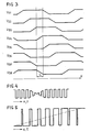
- FIG. 3 represents the output waveforms produced by the function generator 27, as a function of the position of the counter, as a result of the displacement.
- Each of these outputs 31 to 38 is brought to a modulator 28 connected to the oscillator 23.
- These modulators 28 develop from the pulses given by the oscillator 23 and the modulation voltages V 31 to V 38 delivered to each output 31 to 38 of the generator 27, a wave modulated in the form of an alternating voltage V 1 , V 2 or V x . These alternating voltages are then routed to the emitting electrodes 11 to 18.
- FIG. 4 shows the waveform obtained on a transmitting electrode, as a function of a displacement along X at constant speed. It can be seen in FIG. 3, that for a given displacement L, for two (emitting electrodes 14 and 18) of the 8 emitting electrodes 11-18, the modulation voltage V 34 and V 38 varies constantly.
- the emitting electrode 14 is located opposite a receiving electrode (see fig. 2), while the other emitting electrode 18 is located between two receiving electrodes 20, because the extension of the latter only reaches 'about half of its mean interval.
- the electrode 18 therefore has no influence on the receiving electrodes, so that only the emitting electrode 14 located opposite a receiving electrode is connected to V x .
- FIG. 3 also shows that the linear variations of neighboring electrodes follow each other exactly, so that the measurement is linear throughout the displacement range, and that the state of the counter therefore reproduces a linear measurement of the displacement.
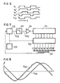
- FIG. 5 illustrates the corresponding modulation function, for displacement at constant speed. Equipped with a low-pass filter, this device is equivalent to a linear amplitude modulation.
- a adder counter 71 which counts continuously.
- the distribution of the voltages V 1 , V 2 and V x applied to the emitting electrodes 11 to 18 therefore follows a fictitious displacement of the receiving electrodes 20, at a speed proportional to the frequency of the counter 71.
- the function generator 72 develops, from the pulses delivered by the oscillator 23 and in accordance with the state of the counter 71, rectangular waves V 1 and V 2 and interpolation waves V x which in this case are waves V x , V x "and V x '"constituting a transition by discrete intermediate values between the waves V 1 and V 2 , as shown in FIG. 6. These waves are then routed, in a sequence and distribution corresponding to the state of the counter 71, to the different electrodes 11 to 18 As previously described, the electrode set to the voltage V x is bordered on one side by two electrodes set to the AC voltage V 1 and on the other side to the AC voltage V 2 of phase opposite to V 1 .
- the signal collected on the receiving electrode 20 is led to a demodulator 22 synchronous with the frequency of V 1 and V 2 and the demodulated signal (V 22 ) conveyed by a low-pass filter 70 to the comparator 24 intended to detect the passage to the zero.
- FIG. 6 illustrates the rectangular waves V 1 and V 2 and the interpolation waves Vx, V x "and V x "'applied to the emitting electrodes 11 to 18.
- the waves V x ', Vx “and V x '” make it possible to obtain, after the synchronous demodulation, a gradual transition between the effects produced by the alternating voltages V 1 and V 2 on the receiving electrode 20.
- the wave V 1 generates, at each cycle in the synchronous demodulator 22, two positive pulses, the V x 'wave, partially desynchronized, one positive pulse, the V x "wave completely desynchronized, none impulse, the wave V x '"a negative impulse, and finally the wave V 2 produces two negative impulses.
- the wave V x ' therefore corresponds to 0.5 V ,, V x " at zero and V x "' at + 0.5 V 2 .
- FIG. 8 represents the demodulated signal (V 22 ) which still has a residual ripple due to the discrete graduations of the transition waveform of V x .
- the voltage (V 70 ) however varies linearly in the region of the zero crossing, so that here, too, a linear relationship is obtained between the moment of the zero crossing, that is to say at the state of the counter at this time, and the displacement X.
Landscapes
- Engineering & Computer Science (AREA)
- Power Engineering (AREA)
- Physics & Mathematics (AREA)
- General Physics & Mathematics (AREA)
- Measurement Of Length, Angles, Or The Like Using Electric Or Magnetic Means (AREA)
- Transmission And Conversion Of Sensor Element Output (AREA)
Applications Claiming Priority (2)
| Application Number | Priority Date | Filing Date | Title |
|---|---|---|---|
| CH8609/80A CH651136A5 (de) | 1980-11-21 | 1980-11-21 | Kapazitives laengen- und winkelmessverfahren. |
| CH8609/80 | 1980-11-21 |
Publications (2)
| Publication Number | Publication Date |
|---|---|
| EP0053091A1 EP0053091A1 (fr) | 1982-06-02 |
| EP0053091B1 true EP0053091B1 (fr) | 1986-03-26 |
Family
ID=4342580
Family Applications (1)
| Application Number | Title | Priority Date | Filing Date |
|---|---|---|---|
| EP81810430A Expired EP0053091B1 (fr) | 1980-11-21 | 1981-10-29 | Procédé de mesure capacitive de longueurs et d'angles |
Country Status (6)
| Country | Link |
|---|---|
| US (1) | US4437055A (ja) |
| EP (1) | EP0053091B1 (ja) |
| JP (1) | JPS57114805A (ja) |
| CH (1) | CH651136A5 (ja) |
| DE (1) | DE3174201D1 (ja) |
| HK (1) | HK81889A (ja) |
Families Citing this family (31)
| Publication number | Priority date | Publication date | Assignee | Title |
|---|---|---|---|---|
| JPS6093311A (ja) * | 1983-10-27 | 1985-05-25 | Mitsutoyo Mfg Co Ltd | 容量式変位測定機 |
| JPS6093312A (ja) * | 1983-10-27 | 1985-05-25 | Mitsutoyo Mfg Co Ltd | 容量式変位測定機 |
| US4522517A (en) * | 1983-11-10 | 1985-06-11 | Wade Kenneth B | Encoder system for dot matrix line printer |
| US4567410A (en) * | 1984-12-03 | 1986-01-28 | Continental Can Company, Inc. | Capacitive article density monitor |
| CN85100991B (zh) * | 1985-04-01 | 1987-06-10 | 西安仪表厂 | 电容式位置传感器 |
| GB2176013B (en) * | 1985-05-23 | 1989-07-19 | Mitutoyo Mfg Co Ltd | Variable capacitance type encoder |
| CH665714A5 (fr) * | 1985-11-22 | 1988-05-31 | Hans Ulrich Meyer | Dispositif de mesure capacitif de longueurs et d'angles. |
| US4839646A (en) * | 1986-02-28 | 1989-06-13 | Royal Melbourne Institute Of Technology Limited | Movement parameter sensor |
| JPS62235504A (ja) * | 1986-04-04 | 1987-10-15 | Mitsutoyo Corp | 容量型位置測定トランスデユ−サ |
| CH670306A5 (ja) * | 1986-11-13 | 1989-05-31 | Hans Ulrich Meyer | |
| FR2607246B1 (fr) * | 1986-11-21 | 1990-05-04 | Thomson Csf | Capteurs de position angulaire ou lineaire, de haute precision, a couplage capacitif |
| GB2223589B (en) * | 1988-09-14 | 1991-07-24 | Valk Rob V D | Measurement of capacitance and parameters related thereto |
| CH685214A5 (fr) * | 1991-10-15 | 1995-04-28 | Hans Ulrich Meyer | Capteur capacitif de position. |
| US5237307A (en) * | 1991-11-27 | 1993-08-17 | The United States Of America As Represented By The United States Department Of Energy | Non-contact tamper sensing by electronic means |
| CH683638A5 (de) * | 1992-01-27 | 1994-04-15 | Hans Meyer | Längenmessgerät. |
| DE4313344A1 (de) * | 1993-04-23 | 1994-11-03 | Roch Pierre Ets | Kapazitive Meßeinrichtung |
| DE4447295A1 (de) * | 1994-11-10 | 1996-05-15 | Siedle Horst Kg | Verfahren und Vorrichtung zur Bestimmung einer jeweiligen örtlichen Position eines Körpers durch kapazitive Abtastung |
| EP0747673B1 (fr) | 1995-06-07 | 2003-03-26 | Brown & Sharpe Tesa S.A. | Dispositif de mesure capacitif |
| US5557584A (en) * | 1995-08-08 | 1996-09-17 | Sonatech, Inc. | Moderate depth underwater surveillance system |
| US5731707A (en) * | 1996-04-17 | 1998-03-24 | Mitutoyo Corporation | Method and apparatus for synthesizing spatial waveforms in an electronic position encoder |
| EP0836076B1 (fr) * | 1996-10-11 | 2002-05-22 | Brown & Sharpe Tesa S.A. | Dispositif de mesure de dimension capacitif |
| AT405104B (de) * | 1997-03-21 | 1999-05-25 | Brasseur Georg Dipl Ing Dr | Kapazitiver drehwinkel- und winkelgeschwindigkeitssensor und messeinrichtung für einen solchen |
| DE10035192C1 (de) * | 2000-07-20 | 2001-10-11 | Carl Mahr Holding Gmbh | Kapazitiver Wegaufnehmer für stromsparende Messgeräte |
| US6473362B1 (en) | 2001-04-30 | 2002-10-29 | Information System Laboratories, Inc. | Narrowband beamformer using nonlinear oscillators |
| JP2003223275A (ja) * | 2001-11-22 | 2003-08-08 | Omron Corp | 入力装置 |
| US6871049B2 (en) * | 2002-03-21 | 2005-03-22 | Cognio, Inc. | Improving the efficiency of power amplifiers in devices using transmit beamforming |
| AU2002349728A1 (en) | 2002-11-08 | 2004-06-18 | Beijing Aerospace Feng Guang Electronic Technical Corp. Ltd. | Magnetic displacement measurement device |
| US7570066B2 (en) * | 2007-11-01 | 2009-08-04 | Seagate Technology Llc | Simultaneous detection of in-plane and out-of-plane position displacement with capacitive sensors |
| CN102914248B (zh) * | 2012-10-11 | 2016-03-02 | 广东盈动高科自动化有限公司 | 被动式线性编码器 |
| US9714846B2 (en) | 2013-12-31 | 2017-07-25 | Chicago Dial Indicator Company | Displacement measuring device with capacitive sensing |
| CN209605843U (zh) | 2019-04-11 | 2019-11-08 | 郝佳 | 感应式位置测量传感器 |
Citations (1)
| Publication number | Priority date | Publication date | Assignee | Title |
|---|---|---|---|---|
| FR2193912A1 (ja) * | 1972-07-27 | 1974-02-22 | Viennet Claude |
Family Cites Families (9)
| Publication number | Priority date | Publication date | Assignee | Title |
|---|---|---|---|---|
| US3297941A (en) | 1963-01-23 | 1967-01-10 | Sogenique Electronics Ltd | Position-sensitive apparatus |
| GB1097760A (en) | 1965-04-27 | 1968-01-03 | Ilford Ltd | Testing material for irregularities of thickness |
| US3491292A (en) | 1967-04-28 | 1970-01-20 | Industrial Nucleonics Corp | Standard sample and method for simulating the effect of moist paper and the like on a capacitive gauge for dielectric materials |
| CH539837A (de) | 1972-03-22 | 1973-07-31 | Ulrich Meyer Hans | Kapazitive Längenmesseinrichtung |
| FR2193192B1 (ja) * | 1972-07-24 | 1979-09-21 | Alais Pierre | |
| US3959723A (en) | 1974-09-13 | 1976-05-25 | Wagner Delmer W | Lumber moisture measurement apparatus which is less sensitive to lumber movement and spacing |
| CH614042A5 (ja) * | 1977-04-20 | 1979-10-31 | Hans Ulrich Meyer | |
| SE411392B (sv) * | 1977-12-09 | 1979-12-17 | Inst Mikrovagsteknik Vid Tekni | Metanordning for kapacitiv bestemning av det inbordes leget hos tva relativt varandra rorliga delar |
| US4296371A (en) | 1980-03-17 | 1981-10-20 | Rca Corporation | System for measuring stylus shoe length |
-
1980
- 1980-11-21 CH CH8609/80A patent/CH651136A5/de not_active IP Right Cessation
-
1981
- 1981-10-29 EP EP81810430A patent/EP0053091B1/fr not_active Expired
- 1981-10-29 DE DE8181810430T patent/DE3174201D1/de not_active Expired
- 1981-11-20 US US06/323,478 patent/US4437055A/en not_active Expired - Lifetime
- 1981-11-20 JP JP56186792A patent/JPS57114805A/ja active Granted
-
1989
- 1989-10-12 HK HK818/89A patent/HK81889A/xx not_active IP Right Cessation
Patent Citations (1)
| Publication number | Priority date | Publication date | Assignee | Title |
|---|---|---|---|---|
| FR2193912A1 (ja) * | 1972-07-27 | 1974-02-22 | Viennet Claude |
Also Published As
| Publication number | Publication date |
|---|---|
| JPS57114805A (en) | 1982-07-16 |
| CH651136A5 (de) | 1985-08-30 |
| EP0053091A1 (fr) | 1982-06-02 |
| HK81889A (en) | 1989-10-20 |
| DE3174201D1 (en) | 1986-04-30 |
| JPH0241685B2 (ja) | 1990-09-19 |
| US4437055A (en) | 1984-03-13 |
Similar Documents
| Publication | Publication Date | Title |
|---|---|---|
| EP0053091B1 (fr) | Procédé de mesure capacitive de longueurs et d'angles | |
| EP0271436B1 (fr) | Capteur capacitif pour la mesure d'un déplacement | |
| US6532061B2 (en) | Measuring the velocity of small moving objects such as cells | |
| EP2181305B1 (fr) | Procede de determination d'une vitesse de rotation d'un capteur vibrant axisymetrique, et dispositif inertiel mettant en oeuvre le procede | |
| EP0648998B1 (fr) | Instrument de mesure de longueurs ou d'angles | |
| EP0225229B1 (fr) | Débitmètre électromagnetique à champ magnetique pulse | |
| EP0565462A1 (fr) | Perfectionnement aux micro-capteurs pendulaires asservis | |
| CH685214A5 (fr) | Capteur capacitif de position. | |
| EP2887014B1 (fr) | Circuit électronique de mesure de la vitesse de rotation dans un gyroscope du type MEMS et procédé pour sa mise en action | |
| FR2685092A1 (fr) | Procede et appareil optique pour detecter des objets dans une zone surveillee. | |
| FR2682835A1 (fr) | Procede de synchronisation de deux signaux. | |
| EP0148518B1 (fr) | Dispositif pour la production d'un signal électrique de vitesse | |
| EP0929795B1 (fr) | Circuit de multiplication de resolution et de determination de sens de deplacement | |
| EP0227591B1 (fr) | Dispositif de mesure capacitif de longueurs et d'angles | |
| FR2568014A1 (fr) | Dispositif de detection de parasites en forme d'impulsion et dispositif de suppression de parasites en forme d'impulsion muni d'un dispositif de detection de parasites en forme d'impulsion | |
| FR2562657A1 (fr) | Dispositif de mesure des longueurs | |
| BE898152A (fr) | Procede et dispositif de detection sans contact du mouvement d'un objet. | |
| CA1330716C (fr) | Dispositif de mesure, dans une gamme etendue, d'un dephasage non reciproque engendre dans un interferometre en anneau et procede de mesure | |
| EP0197801A2 (fr) | Procédé et dispositif de calage en phase rapide d'un signal d'horloge | |
| FR3138529A1 (fr) | Acquisition de distances d'un capteur à une scène | |
| CA1124793A (fr) | Phasemetre multiperiodique | |
| FR2552540A1 (fr) | Dispositif pour mesurer la proximite d'une surface metallique conductrice | |
| EP0210087B1 (fr) | Procédé de mesure de l'aimantation induite dans un bâtiment naval, et dispositif de mise en oeuvre | |
| CH411372A (fr) | Tête de lecture d'angles et utilisation de cette tête | |
| EP0065906B1 (fr) | Dispositif pour la détermination de la vitesse d'un produit en défilement par la méthode de corrélation |
Legal Events
| Date | Code | Title | Description |
|---|---|---|---|
| PUAI | Public reference made under article 153(3) epc to a published international application that has entered the european phase |
Free format text: ORIGINAL CODE: 0009012 |
|
| AK | Designated contracting states |
Designated state(s): DE FR GB |
|
| 17P | Request for examination filed |
Effective date: 19820906 |
|
| GRAA | (expected) grant |
Free format text: ORIGINAL CODE: 0009210 |
|
| AK | Designated contracting states |
Kind code of ref document: B1 Designated state(s): DE FR GB |
|
| REF | Corresponds to: |
Ref document number: 3174201 Country of ref document: DE Date of ref document: 19860430 |
|
| PLBI | Opposition filed |
Free format text: ORIGINAL CODE: 0009260 |
|
| 26 | Opposition filed |
Opponent name: C. E. JOHANSSON AB Effective date: 19861219 |
|
| PLBN | Opposition rejected |
Free format text: ORIGINAL CODE: 0009273 |
|
| STAA | Information on the status of an ep patent application or granted ep patent |
Free format text: STATUS: OPPOSITION REJECTED |
|
| 27O | Opposition rejected |
Effective date: 19880128 |
|
| REG | Reference to a national code |
Ref country code: GB Ref legal event code: 732E |
|
| REG | Reference to a national code |
Ref country code: FR Ref legal event code: TP |
|
| REG | Reference to a national code |
Ref country code: FR Ref legal event code: TP |
|
| PGFP | Annual fee paid to national office [announced via postgrant information from national office to epo] |
Ref country code: FR Payment date: 20000817 Year of fee payment: 20 |
|
| PGFP | Annual fee paid to national office [announced via postgrant information from national office to epo] |
Ref country code: GB Payment date: 20001025 Year of fee payment: 20 |
|
| PGFP | Annual fee paid to national office [announced via postgrant information from national office to epo] |
Ref country code: DE Payment date: 20001127 Year of fee payment: 20 |
|
| PG25 | Lapsed in a contracting state [announced via postgrant information from national office to epo] |
Ref country code: GB Free format text: LAPSE BECAUSE OF EXPIRATION OF PROTECTION Effective date: 20011028 |
|
| REG | Reference to a national code |
Ref country code: GB Ref legal event code: PE20 Effective date: 20011028 |