EP0053048B1 - Système de détection multivoies à émission diversifiée - Google Patents
Système de détection multivoies à émission diversifiée Download PDFInfo
- Publication number
- EP0053048B1 EP0053048B1 EP81401582A EP81401582A EP0053048B1 EP 0053048 B1 EP0053048 B1 EP 0053048B1 EP 81401582 A EP81401582 A EP 81401582A EP 81401582 A EP81401582 A EP 81401582A EP 0053048 B1 EP0053048 B1 EP 0053048B1
- Authority
- EP
- European Patent Office
- Prior art keywords
- angular
- transmission
- filters
- characteristic
- radiating elements
- Prior art date
- Legal status (The legal status is an assumption and is not a legal conclusion. Google has not performed a legal analysis and makes no representation as to the accuracy of the status listed.)
- Expired - Lifetime
Links
- 230000005540 biological transmission Effects 0.000 title claims description 17
- 238000001514 detection method Methods 0.000 title claims description 10
- 238000002592 echocardiography Methods 0.000 claims description 8
- 230000001934 delay Effects 0.000 claims description 7
- 230000015572 biosynthetic process Effects 0.000 claims description 5
- 230000005284 excitation Effects 0.000 claims description 5
- 230000005855 radiation Effects 0.000 claims description 3
- 239000002131 composite material Substances 0.000 description 2
- 238000010586 diagram Methods 0.000 description 2
- 238000000034 method Methods 0.000 description 2
- 238000004040 coloring Methods 0.000 description 1
- 230000001143 conditioned effect Effects 0.000 description 1
- 238000002059 diagnostic imaging Methods 0.000 description 1
- 238000005286 illumination Methods 0.000 description 1
- 238000003384 imaging method Methods 0.000 description 1
- 239000011159 matrix material Substances 0.000 description 1
- 239000000203 mixture Substances 0.000 description 1
- 238000009659 non-destructive testing Methods 0.000 description 1
Images

Classifications
-
- G—PHYSICS
- G01—MEASURING; TESTING
- G01S—RADIO DIRECTION-FINDING; RADIO NAVIGATION; DETERMINING DISTANCE OR VELOCITY BY USE OF RADIO WAVES; LOCATING OR PRESENCE-DETECTING BY USE OF THE REFLECTION OR RERADIATION OF RADIO WAVES; ANALOGOUS ARRANGEMENTS USING OTHER WAVES
- G01S7/00—Details of systems according to groups G01S13/00, G01S15/00, G01S17/00
- G01S7/52—Details of systems according to groups G01S13/00, G01S15/00, G01S17/00 of systems according to group G01S15/00
- G01S7/52003—Techniques for enhancing spatial resolution of targets
-
- G—PHYSICS
- G01—MEASURING; TESTING
- G01S—RADIO DIRECTION-FINDING; RADIO NAVIGATION; DETERMINING DISTANCE OR VELOCITY BY USE OF RADIO WAVES; LOCATING OR PRESENCE-DETECTING BY USE OF THE REFLECTION OR RERADIATION OF RADIO WAVES; ANALOGOUS ARRANGEMENTS USING OTHER WAVES
- G01S15/00—Systems using the reflection or reradiation of acoustic waves, e.g. sonar systems
- G01S15/88—Sonar systems specially adapted for specific applications
- G01S15/89—Sonar systems specially adapted for specific applications for mapping or imaging
Definitions
- the present invention relates to radar or sonar type echo detection systems in which an angular sector is the seat of electromagnetic or ultrasonic radiation emissions.
- the determination of the content of the sector results from the detection and detailed analysis of the signals reflected by the points of space which have been irradiated or insonified. This analysis provides data relating to the angular position and the distance from the targets. Using these data, an image representative of the area explored can be formed on the screen of a cathode ray tube.
- the distance of a target from the transmission-reception assembly is a function of the time elapsed between the transmission of a pulse and the reception of the corresponding echo.
- the angular position of the target can depend on the directivity of the transmission and / or reception means.
- the invention relates more particularly to echo detection systems in which the reception uses a receiver while the emission of the waves is ensured simultaneously by a set of radiating elements.
- This American patent describes in particular a multi-channel detection system comprising on transmission a set of radiating elements which each radiate a continuous signal at a single given carrier frequency, the signal radiated by each element being amplitude modulated by a characteristic signal which is a separate random signal for each element.
- These elements are arranged and radiate in such a way that, in each angular direction of the space, contributions from at least two radiating elements are received. These contributions and these elements are different for each angular direction and each point in space can therefore return an echo formed by a single composite wave.
- a receiver and angular channels comprising suitable filters designed to each recognize the single composite wave reflected by a target in the associated angular direction. Such a system therefore allows a determination of the angular direction from which an echo comes.
- the present invention aims to overcome this drawback by taking advantage of the fact that the number of radiating emission elements, in a system such as that of the American patent cited above, is much lower than the number of angular directions at to separate.
- Such an emission is said to be colored, because it assigns to each direction of the surveillance sector a law of illumination which is specific to it and which will characterize each echo according to its origin. The echo thus personalized can be perceived unequivocally by a set of reception channels.
- the invention consists in separating, in the echo received from a target, the different characteristic signals of each radiating element using suitable filters and then performing a formation of reception channels simply using delays .
- Such a principle can be applied to both radar and sonar, as well as for example to medical imaging or non-destructive testing devices.
- the subject of the invention is a diversified transmission multi-channel detection system comprising transmission means using a set of radiating elements, and reception means capturing echoes due to the reflection of the radiation emitted by said radiating elements, in which said transmission means comprise means of simultaneous pulse excitation of said radiating elements assigning to each of them a characteristic transmission signal, said reception means comprising a receiver connected to several reception channels corresponding respectively to predetermined angular directions, characterized in that each radiating element illuminates substantially the same angular sector, in that said receiving means are arranged at the top of said angular sector and in that said receiving channels comprise several filters, adapted respectively to the particular configuration of the characteristic emission signals and connected to said receiver to separate said characteristic signals in the echoes received, and angular path formation means connected to said filters adapted to compensate, for each angular path, the delays suffered by said characteristic signals. are contained in an echo coming from the corresponding angular direction.
- FIG. 1 one can see a set 1 of emitting electromagnetic or ultrasonic waves making it possible to carry out detection by echoes of the radar or sonar type within the framework of a diversified emission.
- the radioelectric space or the marine propagation medium are related to a system of axes u, v, w whose origin O is located at the center of the set 1 also represents the apex of an angular area of surveillance.
- the transmission assembly 1 comprises for example a matrix arrangement of radiating elements E 1,1 ... E 1, n ... E m, 1 ... E m, n which, in the case of a sonar, are electromechanical transducers capable of insonating the surveillance sector uniformly.
- Each radiating element of the assembly 1 is excited by an emission generator 2 which delivers a short pulse serving as a reference on an output 3.
- a set of connections 4 supplies each of the radiating elements of set 1 with impulse signals 5 the shape of which is represented in FIG. 1 to the left of the generator 2.
- the duration of the excitation signals 5 is T and their form S (t) is chosen so as to be able to identify each radiating element by the content which it emits .
- FIG. 1 shows a grid of space by r lines parallel to v and by s lines parallel to u.
- One of the points P i, k of the set of intersection rxs collects an emission composed of mxn discernible values.
- the polar coordinates ⁇ i, k , ⁇ i, k , ⁇ i, k of the point P i, k determine with the coordinates of the radiating elements E m, n , a particular type of irradiation that can be calculated.
- ⁇ ij is the propagation time along a line joining E j to P i .
- the radiating elements can be arranged in any way, provided that they suitably sample the space and that identifiable codes can be used to predict and unambiguously recognize the combinations which represent this coloring of the space. .
- the signal S (P i, k ) only depends on the coordinates ⁇ i, k and ⁇ i, k .
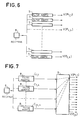
- FIG. 6 shows how a colored emission can be exploited on reception, while the wave receiver 6 does not have its own directivity.
- the echo signals are received by the receiver 6 which delivers a complex electrical signal to the input of a set of channels angular. Each angular channel is assigned to a direction from which the echo comes, which in FIG. 1 is the straight line passing through O and through P i, k .
- the receiver 6 can for example be located at point O and the receiver system of FIG. 6 can comprise rxs angular channels.
- Each angular channel in fact consists of a filter adapted 7 to the signals S (P i, k ) from which a correlation peak V (P i, k ) emerges.
- the adapted filter 7 of the angular path ( ⁇ i, k , ⁇ i, k , ⁇ i, k ) is conditioned to react to the theoretical combination (S (P i, k ) of the emissions produced in P i, k by l It is therefore seen that the diversified emission results in a priori defining a colored space which gives the system of FIG. 6 reception properties provided with angular selectivity.
- FIG. 7 illustrates an embodiment according to the invention of a receiver system provided with the same angular selectivity.
- Filters adapted to code C are supplied by the single receiver 6 which receives the echoes coming from the colored space.
- the filters adapted 8 to each of the emitted codes used to excite the radiating elements of the emission assembly 1 separate each of the codes from the set of codes C 1,1 , C 1,2 , ... C 1, n , ... C min .
- the correlation peaks delivered by the adapted filters 8 are then processed by an angular path formation circuit 9 which has mxn inputs connected to rxs outputs.
- the internal grouping of the circuit 9 for compensating for delays ⁇ ij of the codes which is used to form the channel V (P 1.1 ) has been represented by dashed lines.
- This channel is served by the signals from the mxn filters 8 added with delays which, added to the arrival delays at point P 1.1 of the elementary emissions, give a constant total delay.
- the receiver assembly of Figure 7 is equivalent to the assembly of Figure 6, but it better highlights the "imaging" function of the training circuit 9 which, although located in the reception section of an echo system, provides power separator and an energy contrast based on the geometry of the emission means.
- the forming circuit 9 is a circuit known as "transmission channel formation on reception".
Landscapes
- Engineering & Computer Science (AREA)
- Radar, Positioning & Navigation (AREA)
- Remote Sensing (AREA)
- Physics & Mathematics (AREA)
- Computer Networks & Wireless Communication (AREA)
- General Physics & Mathematics (AREA)
- Acoustics & Sound (AREA)
- Measurement Of Velocity Or Position Using Acoustic Or Ultrasonic Waves (AREA)
Applications Claiming Priority (2)
| Application Number | Priority Date | Filing Date | Title |
|---|---|---|---|
| FR8023519 | 1980-11-04 | ||
| FR8023519A FR2493528A1 (fr) | 1980-11-04 | 1980-11-04 | Systeme de detection multivoies a emission diversifiee |
Publications (2)
| Publication Number | Publication Date |
|---|---|
| EP0053048A1 EP0053048A1 (fr) | 1982-06-02 |
| EP0053048B1 true EP0053048B1 (fr) | 1992-04-29 |
Family
ID=9247655
Family Applications (1)
| Application Number | Title | Priority Date | Filing Date |
|---|---|---|---|
| EP81401582A Expired - Lifetime EP0053048B1 (fr) | 1980-11-04 | 1981-10-13 | Système de détection multivoies à émission diversifiée |
Country Status (5)
| Country | Link |
|---|---|
| US (1) | US4458342A (oth) |
| EP (1) | EP0053048B1 (oth) |
| CA (1) | CA1189609A (oth) |
| DE (1) | DE3177278D1 (oth) |
| FR (1) | FR2493528A1 (oth) |
Families Citing this family (30)
| Publication number | Priority date | Publication date | Assignee | Title |
|---|---|---|---|---|
| DE3644363A1 (de) * | 1985-12-27 | 1987-07-02 | Mitsubishi Electric Corp | System zum abbilden eines objektes mit ultraschall- oder elektromagnetischen wellen |
| EP0252075B1 (en) * | 1986-01-07 | 1990-05-23 | Norges Teknisk-Naturvitenskapelige Forskningsrad | System for detection of objects with given, known characteristics against a background |
| US4809249A (en) * | 1986-04-21 | 1989-02-28 | North American Philips Corporation | Apparatus for ultrasound flow mapping |
| US4855961A (en) * | 1986-07-31 | 1989-08-08 | Woods Hole Oceanographic Institute | Imaging apparatus |
| US4831601A (en) * | 1986-10-31 | 1989-05-16 | Siemens Aktiengesellschaft | Apparatus for transmitting and receiving ultrasonic signals |
| GB2202329A (en) * | 1987-03-05 | 1988-09-21 | British Aerospace | Imaging systems for marine use |
| US4829306A (en) * | 1987-08-31 | 1989-05-09 | Norges Teknisk-Naturvitenskapelige Forskningsråd | System for detection of objects with given, known characteristics against a background |
| US5030956A (en) * | 1989-04-25 | 1991-07-09 | Murphy Quentin M | Radar tomography |
| DE4000698A1 (de) * | 1990-01-12 | 1991-07-18 | Hermesmeyer Alexander C Dipl I | Vorrichtung und verfahren zum erkennen der anwesenheit eines fahrzeugs mittels einer ultraschallvorrichtung |
| US5546356A (en) * | 1993-06-30 | 1996-08-13 | The United States Of America As Represented By The Secretary Of The Navy | Wide beam acoustic projector with sharp cutoff and low side lobes |
| US6027448A (en) * | 1995-03-02 | 2000-02-22 | Acuson Corporation | Ultrasonic transducer and method for harmonic imaging |
| US6009046A (en) * | 1995-03-02 | 1999-12-28 | Acuson Corporation | Ultrasonic harmonic imaging system and method |
| US6005827A (en) | 1995-03-02 | 1999-12-21 | Acuson Corporation | Ultrasonic harmonic imaging system and method |
| US5608690A (en) * | 1995-03-02 | 1997-03-04 | Acuson Corporation | Transmit beamformer with frequency dependent focus |
| US5678554A (en) * | 1996-07-02 | 1997-10-21 | Acuson Corporation | Ultrasound transducer for multiple focusing and method for manufacture thereof |
| US5891037A (en) * | 1997-12-18 | 1999-04-06 | Acuson Corporation | Ultrasonic Doppler imaging system with frequency dependent focus |
| US6160756A (en) | 1998-06-15 | 2000-12-12 | Guigne International Limited | Seabed sonar matrix system |
| US6213947B1 (en) | 1999-03-31 | 2001-04-10 | Acuson Corporation | Medical diagnostic ultrasonic imaging system using coded transmit pulses |
| US6241674B1 (en) | 1999-03-31 | 2001-06-05 | Acuson Corporation | Medical ultrasound diagnostic imaging method and system with nonlinear phase modulation pulse compression |
| US6823021B1 (en) | 2000-10-27 | 2004-11-23 | Greenwich Technologies Associates | Method and apparatus for space division multiple access receiver |
| US7965794B2 (en) | 2000-05-05 | 2011-06-21 | Greenwich Technologies Associates | Method and apparatus for broadcasting with spatially diverse signals |
| CN100406851C (zh) * | 2003-06-04 | 2008-07-30 | 北京师范大学 | 一种侧扫声纳数据采集处理系统及其方法 |
| US9234978B2 (en) * | 2009-07-07 | 2016-01-12 | Westerngeco L.L.C. | Method for positioning the front end of a seismic spread |
| US8305840B2 (en) | 2009-07-14 | 2012-11-06 | Navico, Inc. | Downscan imaging sonar |
| US8300499B2 (en) | 2009-07-14 | 2012-10-30 | Navico, Inc. | Linear and circular downscan imaging sonar |
| US9268020B2 (en) * | 2012-02-10 | 2016-02-23 | Navico Holding As | Sonar assembly for reduced interference |
| US9354312B2 (en) | 2012-07-06 | 2016-05-31 | Navico Holding As | Sonar system using frequency bursts |
| JP5980636B2 (ja) * | 2012-09-20 | 2016-08-31 | 日本無線株式会社 | 物標検出装置 |
| FR3010799B1 (fr) * | 2013-09-13 | 2015-08-28 | Thales Sa | Systeme de detection et de localisation d'objets immerges flottant entre deux eaux tels que des mines a orins et procede associe |
| US10101479B2 (en) | 2014-08-14 | 2018-10-16 | Conocophillips Company | Marine deterministic notch compensation |
Citations (1)
| Publication number | Priority date | Publication date | Assignee | Title |
|---|---|---|---|---|
| US2368069A (en) * | 1943-05-28 | 1945-01-23 | Wright Tool & Forge Company | Procedure and equipment for forging or forming articles |
Family Cites Families (15)
| Publication number | Priority date | Publication date | Assignee | Title |
|---|---|---|---|---|
| US3427617A (en) * | 1959-04-21 | 1969-02-11 | Hazeltine Research Inc | Signal transmitting and receiving system |
| FR1329388A (fr) * | 1961-07-21 | 1963-06-07 | Smith & Sons Ltd S | Perfectionnements aux appareils de sondage par échos |
| GB946839A (en) * | 1961-07-21 | 1964-01-15 | Smith & Sons Ltd S | Improvements in and relating to echo sounding apparatus |
| US3268893A (en) * | 1963-10-08 | 1966-08-23 | Philco Corp | Angle measuring radar utilizing broad beam signal of known form and waveform recognition circuitry |
| FR1528578A (fr) * | 1965-11-19 | 1968-06-14 | Inst Francais Du Petrole | Méthode de détermination des courbes de niveau du fond sous-marin et dispositif pour sa mise en oeuvre |
| US3484737A (en) * | 1968-02-23 | 1969-12-16 | Raytheon Co | Acoustic mapping apparatus |
| US3458854A (en) * | 1968-07-08 | 1969-07-29 | Us Navy | Echo detection and ranging system |
| BE757456A (fr) * | 1969-10-17 | 1971-03-16 | Westinghouse Electric Corp | Appareil sonar a vue laterale |
| US3676584A (en) * | 1970-07-13 | 1972-07-11 | Chris J Plakas | Echo coincidence ultrasonic scanning |
| US3680100A (en) * | 1970-12-15 | 1972-07-25 | Us Navy | Randomly phase coded antenna technique for search radar |
| US3771116A (en) * | 1972-01-12 | 1973-11-06 | Bendix Corp | Method and apparatus for imaging stationary and moving objects |
| US3750152A (en) * | 1972-04-17 | 1973-07-31 | Gen Electric | Pulse-echo phase discriminator using deltic processing |
| US3956749A (en) * | 1973-04-16 | 1976-05-11 | The United States Of America As Represented By The Secretary Of The Navy | Bearing measurement device for a portable attack warning radar |
| US3875550A (en) * | 1973-07-16 | 1975-04-01 | Univ Leland Stanford Junior | Electronically focused acoustic imaging system and method |
| US4119940A (en) * | 1976-10-18 | 1978-10-10 | The Bendix Corporation | Underwater viewing system |
-
1980
- 1980-11-04 FR FR8023519A patent/FR2493528A1/fr active Granted
-
1981
- 1981-10-13 DE DE8181401582T patent/DE3177278D1/de not_active Expired - Fee Related
- 1981-10-13 EP EP81401582A patent/EP0053048B1/fr not_active Expired - Lifetime
- 1981-10-30 US US06/316,913 patent/US4458342A/en not_active Expired - Lifetime
- 1981-11-02 CA CA000389229A patent/CA1189609A/en not_active Expired
Patent Citations (1)
| Publication number | Priority date | Publication date | Assignee | Title |
|---|---|---|---|---|
| US2368069A (en) * | 1943-05-28 | 1945-01-23 | Wright Tool & Forge Company | Procedure and equipment for forging or forming articles |
Non-Patent Citations (1)
| Title |
|---|
| IEEE Radar Conference Publ. 155, 1977, pp. 46-52 * |
Also Published As
| Publication number | Publication date |
|---|---|
| FR2493528A1 (fr) | 1982-05-07 |
| FR2493528B1 (oth) | 1984-08-03 |
| EP0053048A1 (fr) | 1982-06-02 |
| DE3177278D1 (de) | 1992-06-04 |
| US4458342A (en) | 1984-07-03 |
| CA1189609A (en) | 1985-06-25 |
Similar Documents
| Publication | Publication Date | Title |
|---|---|---|
| EP0053048B1 (fr) | Système de détection multivoies à émission diversifiée | |
| US6790182B2 (en) | Ultrasound system and ultrasound diagnostic apparatus for imaging scatterers in a medium | |
| US12055627B2 (en) | Multifan survey system and method | |
| US7852709B1 (en) | Sonar system and process | |
| US11846705B2 (en) | Multimission and multispectral sonar | |
| CN114167427B (zh) | 一种多频段三维探掩埋物声呐装置及方法 | |
| EP0002642B1 (fr) | Système d'antenne à pouvoir séparateur élevé | |
| EP0084466A1 (fr) | Système d'antenne à pouvoir séparateur élevé | |
| EP2317335B1 (en) | Improved beamforming method for analysing signals received by a transducer arrray, and relative detection system | |
| JP2004108826A (ja) | 超音波を用いた距離測定方法および距離測定装置 | |
| US20060083110A1 (en) | Ambient bistatic echo ranging system and method | |
| EP1407292B1 (fr) | Sonar d'imagerie et systeme de detection utilisant un tel sonar | |
| IL301008A (en) | Method and system for imaging a target from coherent waves | |
| US11187801B2 (en) | Spiral sonar | |
| US20240248203A1 (en) | Multifan survey system and method | |
| Hardiman et al. | High repetition rate side looking SONAR | |
| JP2668066B2 (ja) | 超音波映像装置用送受波アレイ | |
| Carter et al. | Sonar Systems | |
| WO2025234884A1 (en) | Modulated beamforming | |
| GB2638288A (en) | An ultrasound sensor apparatus and an operating method thereof | |
| Ramsdale et al. | Effect of element failure and random errors in amplitude and phase on the sidelobe level attainable with a linear array | |
| Stergiopoulos | Sonar Systems | |
| CA2113195A1 (fr) | Systeme d'exploration des fonds marins |
Legal Events
| Date | Code | Title | Description |
|---|---|---|---|
| PUAI | Public reference made under article 153(3) epc to a published international application that has entered the european phase |
Free format text: ORIGINAL CODE: 0009012 |
|
| AK | Designated contracting states |
Designated state(s): BE DE GB IT NL |
|
| 17P | Request for examination filed |
Effective date: 19820621 |
|
| RAP3 | Party data changed (applicant data changed or rights of an application transferred) |
Owner name: THOMSON-CSF |
|
| GRAA | (expected) grant |
Free format text: ORIGINAL CODE: 0009210 |
|
| AK | Designated contracting states |
Kind code of ref document: B1 Designated state(s): BE DE GB IT NL |
|
| ITF | It: translation for a ep patent filed | ||
| REF | Corresponds to: |
Ref document number: 3177278 Country of ref document: DE Date of ref document: 19920604 |
|
| GBT | Gb: translation of ep patent filed (gb section 77(6)(a)/1977) | ||
| PGFP | Annual fee paid to national office [announced via postgrant information from national office to epo] |
Ref country code: BE Payment date: 19920925 Year of fee payment: 12 |
|
| PLBE | No opposition filed within time limit |
Free format text: ORIGINAL CODE: 0009261 |
|
| STAA | Information on the status of an ep patent application or granted ep patent |
Free format text: STATUS: NO OPPOSITION FILED WITHIN TIME LIMIT |
|
| 26N | No opposition filed | ||
| PG25 | Lapsed in a contracting state [announced via postgrant information from national office to epo] |
Ref country code: NL Effective date: 19930501 |
|
| NLV4 | Nl: lapsed or anulled due to non-payment of the annual fee | ||
| ITTA | It: last paid annual fee | ||
| PG25 | Lapsed in a contracting state [announced via postgrant information from national office to epo] |
Ref country code: BE Effective date: 19931031 |
|
| BERE | Be: lapsed |
Owner name: THOMSON-CSF Effective date: 19931031 |
|
| PGFP | Annual fee paid to national office [announced via postgrant information from national office to epo] |
Ref country code: GB Payment date: 19970918 Year of fee payment: 17 Ref country code: DE Payment date: 19970918 Year of fee payment: 17 |
|
| PG25 | Lapsed in a contracting state [announced via postgrant information from national office to epo] |
Ref country code: GB Free format text: LAPSE BECAUSE OF NON-PAYMENT OF DUE FEES Effective date: 19981013 |
|
| GBPC | Gb: european patent ceased through non-payment of renewal fee |
Effective date: 19981013 |
|
| PG25 | Lapsed in a contracting state [announced via postgrant information from national office to epo] |
Ref country code: DE Free format text: LAPSE BECAUSE OF NON-PAYMENT OF DUE FEES Effective date: 19990803 |
|
| APAH | Appeal reference modified |
Free format text: ORIGINAL CODE: EPIDOSCREFNO |