EP0052971B1 - Selbstverriegelnde Kupplungsmutter für elektrische Verbinder - Google Patents
Selbstverriegelnde Kupplungsmutter für elektrische Verbinder Download PDFInfo
- Publication number
- EP0052971B1 EP0052971B1 EP81305279A EP81305279A EP0052971B1 EP 0052971 B1 EP0052971 B1 EP 0052971B1 EP 81305279 A EP81305279 A EP 81305279A EP 81305279 A EP81305279 A EP 81305279A EP 0052971 B1 EP0052971 B1 EP 0052971B1
- Authority
- EP
- European Patent Office
- Prior art keywords
- shell
- nut
- ball receiving
- self
- balls
- Prior art date
- Legal status (The legal status is an assumption and is not a legal conclusion. Google has not performed a legal analysis and makes no representation as to the accuracy of the status listed.)
- Expired
Links
Images
Classifications
-
- H—ELECTRICITY
- H01—ELECTRIC ELEMENTS
- H01R—ELECTRICALLY-CONDUCTIVE CONNECTIONS; STRUCTURAL ASSOCIATIONS OF A PLURALITY OF MUTUALLY-INSULATED ELECTRICAL CONNECTING ELEMENTS; COUPLING DEVICES; CURRENT COLLECTORS
- H01R13/00—Details of coupling devices of the kinds covered by groups H01R12/70 or H01R24/00 - H01R33/00
- H01R13/62—Means for facilitating engagement or disengagement of coupling parts or for holding them in engagement
- H01R13/622—Screw-ring or screw-casing
Definitions
- This invention relates to a self-locking coupling nut for electrical connectors which provides visual and tactile proof of the locked condition.
- Such self-locking devices usually include at least two members adapted for threaded engagement to secure the electrical connector in the engaged condition and a detent apparatus for preventing disengagement of the threaded members except in response to a predetermined force.
- the detenting apparatus may operate either in the radial direction, for example, the devices shown in US Patents 3,587,030; 3,594,700; 3,601,764 and 4,109,990, or in the axial direction, for example, the devices shown in US Patents 3,069,187; 3,462,727; 3,552,777; 3,594,700; 3,808,580 and French Patent Number 2,002,273.
- US Patent No. 3,343,852 discloses a device in which a plurality of individually spring loaded balls or a spring loaded plurality of T-shaped studs are drawn laterally towards the sides of a gear-shaped ratchet wheel when a nut is done up to secure connector members. This could give rise to a jam and the present invention avoids such a problem.
- GB-A-2053590 discloses a connector assembly in which means are provided to give a visible and tactile indication of a mating condition of two connector members, and also an audible indication of the mating condition.
- the visible and tactile indication is given by a split ring (28) which is cammed outwardly by balls (38) which ride up a cap ramp (42) in a cam ring (34).
- the audible ratcheting indication is given by detent protrusions (56) on a spring wave washer (52) which cooperate with detent recesses (50) in the cam ring (34).
- This form of construction has several disadvantages. For example, the cam ring (34) is separate and it can become lost and/or damaged.
- the cam ring and the spring wave washer (52) both need to be specially shaped and manufactured leading to reduced economy in manufacture.
- the balls (38) and cam ring (34) serve only to cam the split ring outwardly to give the visible and tactile indication of a mating condition and do not provide any audible or ratcheting indication.
- the audible or ratcheting indicating does not initially or necessarily indicate a locked condition (since further tightening is required to ensure full compression of the spring wave washer and locking between the detents and detent recesses).
- the ratcheting also causes some resistance to initial threaded engagement.
- the present invention seeks to overcome the foregoing difficulties and disadvantages of the prior art connector assemblies.
- the present invention provides a self-locking coupling nut comprising a first cylindrical shell, a second cylindrical shell for mating engagement with said first shell and having external threads thereon, said first and second shells having cooperating surfaces for locating said shells with respect to each other upon said mating engagement, a nut surrounding said first shell and having threads for threadably engaging said threads of said second shell to secure said first and second shells in said mating engagement, said nut having a plurality of radially extending ball receiving apertures in which respective balls are movably positioned and said nut also having a circumferentially extending spring receiving slot intercepting each of said ball receiving apertures, a spring positioned in said slot for retaining said balls in the ball receiving apertures and for urging said balls inwards towards said first shell, characterised in that said first shell has on its outer surface a radially inwardly located, longitudinally-extending, ball-receiving surface which can be initially aligned with said ball receiving apertures, a ball camming surface extending o
- first shell has ball receiving and camming surfaces
- a separate cam ring is un- ecessary.
- an audible or ratcheting indication is given to indicate that the first and second shells are fully and matingly engaged.
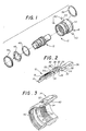
- the self-locking coupling nut 10 includes a first shell 12 and a nut 14 which is normally positioned in a coaxial and overlying relationship with respect to the first shell 12.
- the first shell 12 is preferably from metal, for example, stainless steel or aluminum, although other types of materials may be used in fabricating the first shell 12, if desired.
- the first shell 12 is provided with projections 16 at one end thereof. Threads 18 are formed on the exterior of the first shell 12 adjacent the projections 16. The projections 16 and the threads 18 are adapted to secure the first shell 12 to a cable.
- the projections 16 and the threads 18 are conventional, and do not form part of the present invention.
- a groove 19 is formed in the first shell 12 and extends around its circumference.
- the first shell 12 has a thrust ring 20 extending around the entire circumference thereof.
- the thrust ring 20 includes a radially extending, axially facing thrust surface 22.
- a longitudinally extending ball receiving surface 24 Positioned adjacent the thrust ring 20 is a longitudinally extending ball receiving surface 24.
- the surface 24 extends to a ball camming surface 26 which inclines angularly outwardly from the surface 24.
- the surface 26 extends outwardly to a plurality of lands 28, each having a longitudinally extending, cylindrically shaped, outer surface 30. Adjacent lands 28 are separated by a ball receiving groove 32 which is arcuate in shape.
- the first shell 12 further includes a locating collar 34.
- a tubular portion 36 extends beyond the collar 34.
- a second shell engaging surface 38 is formed at the intersection of the lands 28 and the tubular portion 36.
- the nut 14 is likewise preferably formed from metal, for example, stainless steel or aluminum, although other types of materials may be used in the manufacture of the nut 14, if desired.
- the nut 14 is internally threaded at 40 for threaded engagement with corresponding threads on a second shell (not shown in FIGURES 1 or 3).
- the nut 14 is also internally threaded at 42 to threadedly engage an externally threaded retaining ring 44.
- a thrust washer 46 normally surrounds the first shell 12 and is adapted for engagement with the thrust surface 22 of the thrust ring 20.
- the thrust washer 46 has an inside diameter that is smaller than the outside diameter of the thrust ring 20. Therefore, the thrust washer 46 cannot pass the thrust ring 20 of the first shell 12.
- a sinusoidal or wave-shaped spring 48 is also normally positioned around the first shell 12.
- the wave-shaped spring 48 has an outside dimension which is greater than the inside diameter of the thrust washer 46, and which is also greater than the inside diameter of the retaining ring 44.
- the nut 14 further includes a plurality of ball receiving apertures 50.
- a ball 52 is received in each of the apertures 50 and is freely movable through the aperture.
- a circumferential spring receiving groove 54 is formed in the nut 14 and interconnects all of the ball receiving apertures 50.
- An annular spring 56 is normally received in the groove 54 and functions to retain the balls 52 in the apertures 50.
- the spring 56 comprises a flat spiral that is radially expandable both for assembly into the groove 54 and during operation of the self-locking coupling nut.
- the first shell 12 and the nut 14 are shown in the assembled state.
- the wave-shaped spring 48 and the thrust washer 46 are retained by the retaining ring 44 which is threadedly engaged with the nut 14.
- the thrust washer 46 is engaged with the thrust ring 20 under slight pressure.
- the balls 52 are aligned with the surface 24 and are retained in engagement therewith by the spring 56. It will therefore be understood that other than a very limited amount of rolling friction caused by the engagement of the balls 52 with the surface 24, the nut 14 is freely rotatable relative to the first shell 12.
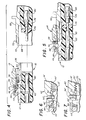
- the first shell 12 receives and retains electrically insulative components 60 and electrically conductive components 62 mounted therein.
- the components 60 and 62 are conventional, and do not form part of the present invention. It will be understood that the interior configuration and dimensions of the first shell 12 may be altered as necessary to accommodate the components 60 and 62 that are desired for a particular application of the present invention.
- FIGURE 4 further illustrates a second shell 66 adapted for mating and locking engagement with the first shell 12 and the nut 14 comprising the self-locking coupling nut 10 of the present invention.
- the second shell 16 is preferably formed from metal, for example, stainless steel or aluminum. However, the second shell 16 may be formed from other materials in accordance with particular requirements.
- the second shell 66 includes a tubular extension 68 having a first shell engaging surface 70 at one end thereof.
- the interior of the extension 68 of the second shell 66 is dimensioned to receive the tubular extension 36 of the first shell 12 therein.
- the exterior of the tubular extension 68 is provided with external threads 72 wh.ich are dimensioned and adapted for mating threaded engagement with the internal threads 40 of the nut 14.
- the interior of the second shell 66 receives electrically insulative components 74 and 76 and electrically conductive components 80.
- the function of the self-locking coupling nut 10 of the present invention is to secure the components 80 of the second shell 66 in electrically conductive engagement with the components 62 of the first shell 12.
- the interior configuration and dimensions of the second shell 66 may be altered in order to suit the requirements of the components 74, 76 and 80 that are to be utilized in a particular application of the invention.
- FIGURE 5 illustrates the component parts of the self-locking coupling nut 10 in the assembled state.
- the tubular extension 36 of the first shell 12 is initially inserted into the tubular extension 68 of the second shell 66, and the two components are moved toward one another. This causes the threads 72 of the second shell 66 to come into engagement with the threads 40 of the nut 14.
- the nut 14 is then rotated in order to establish a threaded connection between the threads 72 and 40 and thereby secure the engagement between the first shell 12 and the components 60 and 62 carried thereby and the second shell 66 and the components 74, 76 and 80 carried thereby.
- the initial threaded engagement between the nut 14 and the second shell 66 is facilitated because at this point the nut 14 is relatively freely rotatable on the first shell 12.
- Relative axial movement rightwardly (FIGURES 4 and 5) of the nut 14 with respect to the first shell 12 also causes the balls 52 to move upwardly on the camming surface 26 of the first shell 12 against the action of the spring 56.
- the balls 52 enter the grooves 32 between the lands 28.
- rotation of the nut 14 relative to the first shell 12 in either direction can only occur by generating sufficient force to move the balls upwardly and out of the grooves 32, across the surfaces 30 of the lands 28, and into the next adjacent grooves 32.
- This movement is resisted by the spring 56 which generates a predetermined force that urges the balls 52 to move radially inwardly.
- initial rotation of the nut 14 of the present invention to lock the first shell 12 in engagement with the second shell 66 does not cause a ratcheting and/or detent effect.
- further rotation of the nut 14 causes ratcheting and/or detenting. This effect is both audible and tactile, and provides an indication that the self-locking coupling nut 10 has substantially reached its fully engaged condition.
- the balls 52 are positioned substantially radially outwardly with respect to their positioning when the component parts are disengaged. This in turn causes outward radial positioning of the spring 56.
- the spring 56 is dimensioned so that it entirely received within the groove 54 when the component parts of the self-locking coupling nut 10 are disengaged, and so that it projects outwardly beyond the confines of the groove 54 when the component parts are fully engaged. This positioning of the spring 56 provides both visual and tactile proof of the fully engaged and locked status of the self-locking coupling nut 10.
- the spring 56 has a surface 58 that is fully exposed when the self-locking coupling nut 10 is in the locked status, but which is otherwise hidden from view by the walls of the groove 54.
- the groove 19 of the first shell 12 is normally hidden, but is exposed when self-locking coupling nut 10 is in the locked status.
- the surface 58 and the groove 19 are preferably painted a bright color such as yellow to facilitate visual inspections and proof of the locked status of the self-locking coupling nut 10.
- the nut 14 Whenever it is desired to disengage the shell 66 from the shell 12, the nut 14 is rotated to disengage the threads 40 from the threads 72. Of course, the nut 14 cannot be rotated unless sufficient torque is developed to overcome the detenting action of the spring 56, the balls 52 and the grooves 32. As the self-locking coupling nut 10 is returned to its unlocked status, the component parts of the shell 10 and the nut 14 are returned to the positions shown in FIGURE 4 under the action of the spring 48.
- FIGURES 6 and 7 A self-locking coupling nut 82 comprising a second embodiment of the invention is illustrated in FIGURES 6 and 7.
- Many of the component parts of the self-locking coupling nut 82 are substantially identical in construction and function to component parts of the self-locking coupling nut 10.
- Such identical component parts are designated in FIGURES 6 and 7 with the same reference numerals utilized hereinabove in the description of the self-locking coupling nut 10, but are differentiated therefrom by means of a prime (') designation.
- the self-locking coupling nut 82 differs from the self-locking coupling nut 10 primarily in the substitution of a coil spring 84 for the wave-shaped spring 48 of the self-locking coupling nut 10.
- the coil spring 84 is trapped between the retaining ring 44' and the thrust washer 46', and is adapted to be substantially compressed when the component parts of the self-locking coupling nut 82 are assembled.
- Other types of springs adapted for compression between the retaining ring and the thrust washer may also be utilised in the practice of the invention.
Landscapes
- Transmission Devices (AREA)
- Details Of Connecting Devices For Male And Female Coupling (AREA)
- Snaps, Bayonet Connections, Set Pins, And Snap Rings (AREA)
Claims (6)
Applications Claiming Priority (2)
| Application Number | Priority Date | Filing Date | Title |
|---|---|---|---|
| US06/209,429 US4407529A (en) | 1980-11-24 | 1980-11-24 | Self-locking coupling nut for electrical connectors |
| US209429 | 1980-11-24 |
Publications (3)
| Publication Number | Publication Date |
|---|---|
| EP0052971A2 EP0052971A2 (de) | 1982-06-02 |
| EP0052971A3 EP0052971A3 (en) | 1982-06-30 |
| EP0052971B1 true EP0052971B1 (de) | 1985-02-20 |
Family
ID=22778720
Family Applications (1)
| Application Number | Title | Priority Date | Filing Date |
|---|---|---|---|
| EP81305279A Expired EP0052971B1 (de) | 1980-11-24 | 1981-11-06 | Selbstverriegelnde Kupplungsmutter für elektrische Verbinder |
Country Status (5)
| Country | Link |
|---|---|
| US (1) | US4407529A (de) |
| EP (1) | EP0052971B1 (de) |
| JP (1) | JPS57154509A (de) |
| CA (1) | CA1170328A (de) |
| DE (1) | DE3169097D1 (de) |
Families Citing this family (94)
| Publication number | Priority date | Publication date | Assignee | Title |
|---|---|---|---|---|
| US4462653A (en) * | 1981-11-27 | 1984-07-31 | Bendix Corporation | Electrical connector assembly |
| US4544224A (en) * | 1982-09-07 | 1985-10-01 | International Telephone & Telegraph Corp. | Self-locking electrical connector |
| US4508406A (en) * | 1982-09-30 | 1985-04-02 | Allied Corporation | Electrical connector assembly having an anti-decoupling device |
| US4596431A (en) * | 1985-02-08 | 1986-06-24 | Automation Industries | Tactile coupling indicator for an electrical connector |
| US4808123A (en) * | 1987-02-04 | 1989-02-28 | Diverse Termination Products, Inc. | Self-locking strain-relief end bell for electrical connector assembly |
| US4820184A (en) * | 1987-10-05 | 1989-04-11 | Interconnection Products Incorporated | Electrical connector retaining ratchet |
| JPH0350775U (de) * | 1989-09-25 | 1991-05-17 | ||
| US4984995A (en) * | 1989-11-13 | 1991-01-15 | Icore International, Inc. | Anti-decoupling device for electrical conduit connector |
| JPH0460723U (de) * | 1990-10-03 | 1992-05-25 | ||
| US5145394A (en) * | 1991-10-03 | 1992-09-08 | G & H Technology, Inc. | Anti-rotation assembly for interconnect devices |
| US5322451A (en) * | 1992-11-10 | 1994-06-21 | Woodhead Industries, Inc. | Vibration resistant electrical coupling with tactile indication |
| CA2128172C (en) * | 1993-08-27 | 1997-05-13 | Alan R. Miklos | Self-seating connector adapter |
| JPH07153518A (ja) * | 1993-09-13 | 1995-06-16 | Labinal Components & Syst Inc | 電気用コネクタ |
| US5456614A (en) * | 1994-01-25 | 1995-10-10 | John Mezzalingua Assoc., Inc. | Coaxial cable end connector with signal seal |
| FR2766974A1 (fr) * | 1997-07-30 | 1999-01-29 | Socapex Amphenol | Dispositif de connexion electrique |
| US6135800A (en) * | 1998-12-22 | 2000-10-24 | Conxall Corporation | Anti-rotational electrical connector |
| US6135799A (en) * | 1999-04-05 | 2000-10-24 | Unistar Industries | Coupling nut retention apparatus |
| US6666726B2 (en) * | 2000-07-31 | 2003-12-23 | Tru Corporation | Electrical connector assembly |
| US6824415B2 (en) | 2001-11-01 | 2004-11-30 | Andrew Corporation | Coaxial connector with spring loaded coupling mechanism |
| US6725761B1 (en) | 2002-09-30 | 2004-04-27 | Prince Manufacturing Corporation | Spooling device assembly for hydraulic cylinder and method of assembling same |
| US7201404B1 (en) * | 2003-12-17 | 2007-04-10 | Related Metal Fabrication, Inc. | Union nut with lock member |
| FR2867253B1 (fr) * | 2004-03-05 | 2007-10-12 | Staubli Sa Ets | Raccord de jonction amovible et procede de raccordement correspondant |
| US8157589B2 (en) | 2004-11-24 | 2012-04-17 | John Mezzalingua Associates, Inc. | Connector having a conductively coated member and method of use thereof |
| US20060110977A1 (en) | 2004-11-24 | 2006-05-25 | Roger Matthews | Connector having conductive member and method of use thereof |
| US7114990B2 (en) | 2005-01-25 | 2006-10-03 | Corning Gilbert Incorporated | Coaxial cable connector with grounding member |
| US7762279B2 (en) | 2005-11-05 | 2010-07-27 | Snap-Tite Technologies, Inc. | Threaded coupling with flow shutoff |
| US7575024B2 (en) | 2005-11-05 | 2009-08-18 | Snap-Tite Technologies, Inc. | Threaded coupling with flow shutoff |
| US7566236B2 (en) | 2007-06-14 | 2009-07-28 | Thomas & Betts International, Inc. | Constant force coaxial cable connector |
| US7798849B2 (en) * | 2008-08-28 | 2010-09-21 | John Mezzalingua Associates, Inc. | Connecting assembly for an end of a coaxial cable and method of connecting a coaxial cable to a connector |
| US8113875B2 (en) | 2008-09-30 | 2012-02-14 | Belden Inc. | Cable connector |
| US8025518B2 (en) | 2009-02-24 | 2011-09-27 | Corning Gilbert Inc. | Coaxial connector with dual-grip nut |
| US8029315B2 (en) | 2009-04-01 | 2011-10-04 | John Mezzalingua Associates, Inc. | Coaxial cable connector with improved physical and RF sealing |
| US7824216B2 (en) | 2009-04-02 | 2010-11-02 | John Mezzalingua Associates, Inc. | Coaxial cable continuity connector |
| US7892005B2 (en) | 2009-05-19 | 2011-02-22 | John Mezzalingua Associates, Inc. | Click-tight coaxial cable continuity connector |
| US8444445B2 (en) | 2009-05-22 | 2013-05-21 | Ppc Broadband, Inc. | Coaxial cable connector having electrical continuity member |
| US8287320B2 (en) | 2009-05-22 | 2012-10-16 | John Mezzalingua Associates, Inc. | Coaxial cable connector having electrical continuity member |
| US9570845B2 (en) | 2009-05-22 | 2017-02-14 | Ppc Broadband, Inc. | Connector having a continuity member operable in a radial direction |
| US9017101B2 (en) | 2011-03-30 | 2015-04-28 | Ppc Broadband, Inc. | Continuity maintaining biasing member |
| US8573996B2 (en) | 2009-05-22 | 2013-11-05 | Ppc Broadband, Inc. | Coaxial cable connector having electrical continuity member |
| US8272893B2 (en) | 2009-11-16 | 2012-09-25 | Corning Gilbert Inc. | Integrally conductive and shielded coaxial cable connector |
| TWI549386B (zh) | 2010-04-13 | 2016-09-11 | 康寧吉伯特公司 | 具有防止進入及改良接地之同軸連接器 |
| FR2961883B1 (fr) | 2010-06-24 | 2014-01-17 | Souriau | Connecteur a vis a verrouillage renforce |
| US8152551B2 (en) | 2010-07-22 | 2012-04-10 | John Mezzalingua Associates, Inc. | Port seizing cable connector nut and assembly |
| US8079860B1 (en) | 2010-07-22 | 2011-12-20 | John Mezzalingua Associates, Inc. | Cable connector having threaded locking collet and nut |
| US8113879B1 (en) | 2010-07-27 | 2012-02-14 | John Mezzalingua Associates, Inc. | One-piece compression connector body for coaxial cable connector |
| US8888526B2 (en) | 2010-08-10 | 2014-11-18 | Corning Gilbert, Inc. | Coaxial cable connector with radio frequency interference and grounding shield |
| US8167636B1 (en) | 2010-10-15 | 2012-05-01 | John Mezzalingua Associates, Inc. | Connector having a continuity member |
| US8167635B1 (en) | 2010-10-18 | 2012-05-01 | John Mezzalingua Associates, Inc. | Dielectric sealing member and method of use thereof |
| US8075338B1 (en) | 2010-10-18 | 2011-12-13 | John Mezzalingua Associates, Inc. | Connector having a constant contact post |
| US8323053B2 (en) | 2010-10-18 | 2012-12-04 | John Mezzalingua Associates, Inc. | Connector having a constant contact nut |
| US8167646B1 (en) | 2010-10-18 | 2012-05-01 | John Mezzalingua Associates, Inc. | Connector having electrical continuity about an inner dielectric and method of use thereof |
| TWI558022B (zh) | 2010-10-27 | 2016-11-11 | 康寧吉伯特公司 | 具有耦合器和固持及釋放機制的推入固定式纜線連接器 |
| US8337229B2 (en) | 2010-11-11 | 2012-12-25 | John Mezzalingua Associates, Inc. | Connector having a nut-body continuity element and method of use thereof |
| US8414322B2 (en) | 2010-12-14 | 2013-04-09 | Ppc Broadband, Inc. | Push-on CATV port terminator |
| US8398421B2 (en) | 2011-02-01 | 2013-03-19 | John Mezzalingua Associates, Inc. | Connector having a dielectric seal and method of use thereof |
| US8157588B1 (en) | 2011-02-08 | 2012-04-17 | Belden Inc. | Cable connector with biasing element |
| US8465322B2 (en) | 2011-03-25 | 2013-06-18 | Ppc Broadband, Inc. | Coaxial cable connector |
| US8342879B2 (en) | 2011-03-25 | 2013-01-01 | John Mezzalingua Associates, Inc. | Coaxial cable connector |
| US8366481B2 (en) | 2011-03-30 | 2013-02-05 | John Mezzalingua Associates, Inc. | Continuity maintaining biasing member |
| US8388377B2 (en) | 2011-04-01 | 2013-03-05 | John Mezzalingua Associates, Inc. | Slide actuated coaxial cable connector |
| US8348697B2 (en) | 2011-04-22 | 2013-01-08 | John Mezzalingua Associates, Inc. | Coaxial cable connector having slotted post member |
| WO2012162431A2 (en) | 2011-05-26 | 2012-11-29 | Belden Inc. | Coaxial cable connector with conductive seal |
| US9711917B2 (en) | 2011-05-26 | 2017-07-18 | Ppc Broadband, Inc. | Band spring continuity member for coaxial cable connector |
| US8758050B2 (en) | 2011-06-10 | 2014-06-24 | Hiscock & Barclay LLP | Connector having a coupling member for locking onto a port and maintaining electrical continuity |
| US8591244B2 (en) | 2011-07-08 | 2013-11-26 | Ppc Broadband, Inc. | Cable connector |
| US9190744B2 (en) | 2011-09-14 | 2015-11-17 | Corning Optical Communications Rf Llc | Coaxial cable connector with radio frequency interference and grounding shield |
| US20130072057A1 (en) | 2011-09-15 | 2013-03-21 | Donald Andrew Burris | Coaxial cable connector with integral radio frequency interference and grounding shield |
| US9147955B2 (en) | 2011-11-02 | 2015-09-29 | Ppc Broadband, Inc. | Continuity providing port |
| US9136654B2 (en) | 2012-01-05 | 2015-09-15 | Corning Gilbert, Inc. | Quick mount connector for a coaxial cable |
| CN102570215B (zh) * | 2012-01-12 | 2014-04-09 | 威斯翰(北京)建筑科技有限公司 | 一种电连接器 |
| US9407016B2 (en) | 2012-02-22 | 2016-08-02 | Corning Optical Communications Rf Llc | Coaxial cable connector with integral continuity contacting portion |
| US9287659B2 (en) | 2012-10-16 | 2016-03-15 | Corning Optical Communications Rf Llc | Coaxial cable connector with integral RFI protection |
| US9147963B2 (en) | 2012-11-29 | 2015-09-29 | Corning Gilbert Inc. | Hardline coaxial connector with a locking ferrule |
| US9708865B2 (en) * | 2012-12-13 | 2017-07-18 | Vetco Gray Inc. | Ratcheting anti-rotation lock for threaded connectors |
| US9153911B2 (en) | 2013-02-19 | 2015-10-06 | Corning Gilbert Inc. | Coaxial cable continuity connector |
| US9172154B2 (en) | 2013-03-15 | 2015-10-27 | Corning Gilbert Inc. | Coaxial cable connector with integral RFI protection |
| US9397441B2 (en) * | 2013-03-15 | 2016-07-19 | Cinch Connections, Inc. | Connector with anti-decoupling mechanism |
| US9130281B2 (en) | 2013-04-17 | 2015-09-08 | Ppc Broadband, Inc. | Post assembly for coaxial cable connectors |
| US10290958B2 (en) | 2013-04-29 | 2019-05-14 | Corning Optical Communications Rf Llc | Coaxial cable connector with integral RFI protection and biasing ring |
| CN105284015B (zh) | 2013-05-20 | 2019-03-08 | 康宁光电通信Rf有限责任公司 | 具有整体rfi保护的同轴电缆连接器 |
| US9548557B2 (en) | 2013-06-26 | 2017-01-17 | Corning Optical Communications LLC | Connector assemblies and methods of manufacture |
| US9048599B2 (en) | 2013-10-28 | 2015-06-02 | Corning Gilbert Inc. | Coaxial cable connector having a gripping member with a notch and disposed inside a shell |
| US9548572B2 (en) | 2014-11-03 | 2017-01-17 | Corning Optical Communications LLC | Coaxial cable connector having a coupler and a post with a contacting portion and a shoulder |
| US9590287B2 (en) | 2015-02-20 | 2017-03-07 | Corning Optical Communications Rf Llc | Surge protected coaxial termination |
| US10033122B2 (en) | 2015-02-20 | 2018-07-24 | Corning Optical Communications Rf Llc | Cable or conduit connector with jacket retention feature |
| US10211547B2 (en) | 2015-09-03 | 2019-02-19 | Corning Optical Communications Rf Llc | Coaxial cable connector |
| US10337656B2 (en) * | 2015-10-27 | 2019-07-02 | Ford Global Technologies, Llc | Quick connect with visual indicator |
| US9525220B1 (en) | 2015-11-25 | 2016-12-20 | Corning Optical Communications LLC | Coaxial cable connector |
| WO2018125890A1 (en) * | 2016-12-28 | 2018-07-05 | Pct International, Inc. | Progressive lock washer assembly for coaxial cable connectors |
| US9831596B1 (en) | 2016-12-29 | 2017-11-28 | Itt Manufacturing Enterprises Llc | Flame-proof connectors |
| DE102018101964B3 (de) * | 2018-01-30 | 2019-06-13 | Te Connectivity Germany Gmbh | Steckverbinder und Steckverbinderaufnahme |
| EP4046243B1 (de) * | 2019-10-15 | 2026-01-21 | Stemco Products, Inc. | Drehmomentbegrenzungsmutter |
| CN114079200B (zh) * | 2020-08-11 | 2023-12-26 | 正凌精密工业(广东)有限公司 | 具有直接锁固与旋转预顶出功能的连接器 |
| US12034264B2 (en) | 2021-03-31 | 2024-07-09 | Corning Optical Communications Rf Llc | Coaxial cable connector assemblies with outer conductor engagement features and methods for using the same |
Family Cites Families (28)
| Publication number | Priority date | Publication date | Assignee | Title |
|---|---|---|---|---|
| US562029A (en) * | 1896-06-16 | Engine | ||
| US794766A (en) * | 1904-01-27 | 1905-07-18 | Samuel G Wright | Hose-coupling. |
| US975905A (en) * | 1909-02-19 | 1910-11-15 | Ingersoll Rand Co | Hammer-drill. |
| US1289867A (en) * | 1918-03-16 | 1918-12-31 | William J P Moore | Cotter-pin. |
| US1467907A (en) * | 1922-04-15 | 1923-09-11 | Miyagi Takeo | Nut lock |
| DE467544C (de) | 1927-09-27 | 1928-10-27 | Karl Brieden & Co | Gesicherte Verschraubung fuer Schlauch- und Rohranschluesse an Pressluftwerkzeugen |
| US2372888A (en) * | 1944-04-20 | 1945-04-03 | Duggan James Edward | Nut structure |
| US2688736A (en) * | 1953-07-10 | 1954-09-07 | Joy Mfg Co | Connector with magnetically controlled lock |
| FR1221842A (fr) | 1959-01-15 | 1960-06-03 | Perfectionnements apportés aux dispositifs de raccords, notamment pour tuyaux | |
| US3008116A (en) * | 1959-04-27 | 1961-11-07 | Cannon Electric Co | Moisture-proof quick-disconnect device |
| US3069187A (en) * | 1959-06-12 | 1962-12-18 | Parker Hannifin Corp | Coupling for tubes |
| US3255796A (en) * | 1964-02-04 | 1966-06-14 | Richard D Tobey | Retainer mechanism |
| US3343852A (en) * | 1964-06-08 | 1967-09-26 | Cannon Electric Great Britain | Locking nuts and electrical connectors incorporating locking nuts |
| US3393927A (en) * | 1966-02-07 | 1968-07-23 | Itt | Electrical connector |
| GB1140606A (en) * | 1966-06-03 | 1969-01-22 | Cannon Electric Great Britain | Coupling arrangement for two cylindrical members |
| GB1260119A (en) | 1968-02-20 | 1972-01-12 | Electronic Components Ltd | Electric connectors |
| US3552777A (en) * | 1968-02-23 | 1971-01-05 | United Air Lines Inc | Self-locking device for couplings |
| US3587032A (en) * | 1968-08-19 | 1971-06-22 | Bendix Corp | Separable connector with locking means |
| US3609632A (en) * | 1968-08-19 | 1971-09-28 | Trw Inc | Releasable electrical connector |
| US3601764A (en) * | 1969-01-28 | 1971-08-24 | Bunker Ramo | Lock device for coupling means |
| US3594700A (en) * | 1969-08-20 | 1971-07-20 | Pyle National Co | Electrical connector with threaded coupling nut lock |
| US3669472A (en) * | 1971-02-03 | 1972-06-13 | Wiggins Inc E B | Coupling device with spring locking detent means |
| US3786396A (en) * | 1972-04-28 | 1974-01-15 | Bunker Ramo | Electrical connector with locking device |
| US3808580A (en) * | 1972-12-18 | 1974-04-30 | Matrix Science Corp | Self-locking coupling nut for electrical connectors |
| US3917373A (en) * | 1974-06-05 | 1975-11-04 | Bunker Ramo | Coupling ring assembly |
| US4056298A (en) * | 1976-10-07 | 1977-11-01 | Automation Industries, Inc. | Electrical connector with coupling assembly breech retaining means |
| US4109990A (en) * | 1977-05-26 | 1978-08-29 | The Bendix Corporation | Electrical connector assembly having anti-decoupling mechanism |
| US4290662A (en) * | 1979-07-11 | 1981-09-22 | Bunker Ramo Corporation | Connector assembly with visual, tactile and audible indication |
-
1980
- 1980-11-24 US US06/209,429 patent/US4407529A/en not_active Expired - Lifetime
-
1981
- 1981-11-06 EP EP81305279A patent/EP0052971B1/de not_active Expired
- 1981-11-06 DE DE8181305279T patent/DE3169097D1/de not_active Expired
- 1981-11-21 JP JP56186150A patent/JPS57154509A/ja active Pending
- 1981-11-23 CA CA000390656A patent/CA1170328A/en not_active Expired
Also Published As
| Publication number | Publication date |
|---|---|
| CA1170328A (en) | 1984-07-03 |
| DE3169097D1 (en) | 1985-03-28 |
| EP0052971A3 (en) | 1982-06-30 |
| US4407529A (en) | 1983-10-04 |
| JPS57154509A (en) | 1982-09-24 |
| EP0052971A2 (de) | 1982-06-02 |
Similar Documents
| Publication | Publication Date | Title |
|---|---|---|
| EP0052971B1 (de) | Selbstverriegelnde Kupplungsmutter für elektrische Verbinder | |
| US5653605A (en) | Locking coupling | |
| EP2950401B1 (de) | Elektrischer steckverbinder | |
| US4046451A (en) | Connector for coaxial cable with annularly corrugated outer conductor | |
| US5662488A (en) | Quick connect coupling system for rapidly joining connectors and/or other elongated bodies | |
| US4703988A (en) | Self-locking electric connector | |
| EP1924800B1 (de) | Selbstsperrende und selbstbindende starre kupplung | |
| CA1073981A (en) | Theftproof electrical connector assembly | |
| US5788443A (en) | Male coupling with movable threaded segments | |
| US3786396A (en) | Electrical connector with locking device | |
| US7806621B2 (en) | Locking device for connector assembly | |
| US6086400A (en) | Self-locking cable connector coupling | |
| US3462727A (en) | Electrical connector or the like having coupling nut detent means | |
| US3422390A (en) | Coupling device | |
| US6168213B1 (en) | Connector and connection method | |
| US4348956A (en) | Artillery shell comprising two sections having complementary coupling members for connecting the sections together | |
| US3393927A (en) | Electrical connector | |
| CA1221429A (en) | Electrical connectors | |
| EP0312382B1 (de) | Einstellvorrichtung für Seilzug | |
| CA2893600C (en) | Cable connector system | |
| GB1577804A (en) | Coupling | |
| EP0604196B1 (de) | Rastverbindungen für Aggregate sowie Befestigungselemente dafür | |
| US20070223994A1 (en) | Integrated locking device | |
| EP4207509A1 (de) | Schutzendabdeckung, verbinder und verbinderanordnung | |
| JPS63186020A (ja) | 遠隔制御装置 |
Legal Events
| Date | Code | Title | Description |
|---|---|---|---|
| PUAI | Public reference made under article 153(3) epc to a published international application that has entered the european phase |
Free format text: ORIGINAL CODE: 0009012 |
|
| PUAL | Search report despatched |
Free format text: ORIGINAL CODE: 0009013 |
|
| AK | Designated contracting states |
Designated state(s): DE FR GB IT |
|
| AK | Designated contracting states |
Designated state(s): DE FR GB IT |
|
| 17P | Request for examination filed |
Effective date: 19821201 |
|
| ITF | It: translation for a ep patent filed | ||
| GRAA | (expected) grant |
Free format text: ORIGINAL CODE: 0009210 |
|
| AK | Designated contracting states |
Designated state(s): DE FR GB IT |
|
| REF | Corresponds to: |
Ref document number: 3169097 Country of ref document: DE Date of ref document: 19850328 |
|
| ET | Fr: translation filed | ||
| PLBE | No opposition filed within time limit |
Free format text: ORIGINAL CODE: 0009261 |
|
| STAA | Information on the status of an ep patent application or granted ep patent |
Free format text: STATUS: NO OPPOSITION FILED WITHIN TIME LIMIT |
|
| 26N | No opposition filed | ||
| PG25 | Lapsed in a contracting state [announced via postgrant information from national office to epo] |
Ref country code: GB Effective date: 19881106 |
|
| GBPC | Gb: european patent ceased through non-payment of renewal fee | ||
| PG25 | Lapsed in a contracting state [announced via postgrant information from national office to epo] |
Ref country code: FR Free format text: LAPSE BECAUSE OF NON-PAYMENT OF DUE FEES Effective date: 19890731 |
|
| PG25 | Lapsed in a contracting state [announced via postgrant information from national office to epo] |
Ref country code: DE Effective date: 19890801 |
|
| REG | Reference to a national code |
Ref country code: FR Ref legal event code: ST |