EP0052813A2 - Method for the examination of a moving reflecting or transparent sheet, and device for carrying out said method - Google Patents
Method for the examination of a moving reflecting or transparent sheet, and device for carrying out said method Download PDFInfo
- Publication number
- EP0052813A2 EP0052813A2 EP81109444A EP81109444A EP0052813A2 EP 0052813 A2 EP0052813 A2 EP 0052813A2 EP 81109444 A EP81109444 A EP 81109444A EP 81109444 A EP81109444 A EP 81109444A EP 0052813 A2 EP0052813 A2 EP 0052813A2
- Authority
- EP
- European Patent Office
- Prior art keywords
- sensors
- row
- web
- light
- signal
- Prior art date
- Legal status (The legal status is an assumption and is not a legal conclusion. Google has not performed a legal analysis and makes no representation as to the accuracy of the status listed.)
- Withdrawn
Links
Images


Classifications
-
- G—PHYSICS
- G01—MEASURING; TESTING
- G01N—INVESTIGATING OR ANALYSING MATERIALS BY DETERMINING THEIR CHEMICAL OR PHYSICAL PROPERTIES
- G01N21/00—Investigating or analysing materials by the use of optical means, i.e. using sub-millimetre waves, infrared, visible or ultraviolet light
- G01N21/84—Systems specially adapted for particular applications
- G01N21/88—Investigating the presence of flaws or contamination
- G01N21/89—Investigating the presence of flaws or contamination in moving material, e.g. running paper or textiles
- G01N21/892—Investigating the presence of flaws or contamination in moving material, e.g. running paper or textiles characterised by the flaw, defect or object feature examined
- G01N21/896—Optical defects in or on transparent materials, e.g. distortion, surface flaws in conveyed flat sheet or rod
-
- G—PHYSICS
- G01—MEASURING; TESTING
- G01N—INVESTIGATING OR ANALYSING MATERIALS BY DETERMINING THEIR CHEMICAL OR PHYSICAL PROPERTIES
- G01N21/00—Investigating or analysing materials by the use of optical means, i.e. using sub-millimetre waves, infrared, visible or ultraviolet light
- G01N21/84—Systems specially adapted for particular applications
- G01N21/88—Investigating the presence of flaws or contamination
- G01N21/89—Investigating the presence of flaws or contamination in moving material, e.g. running paper or textiles
Definitions
- the invention relates to a method for viewing a reflecting and / or transparent, moving web, in particular of textile material, with at least one light source illuminating the web surface, with photoelectric sensors arranged in a row transverse to the web and arranged at a distance from the web are and receive the reflected or transmitted light and generate an electrical signal according to the intensity of the light falling on them, which is amplified and fed into an electrical network which processes the signal based on given error criteria.
- DE-PS 1 917 877 discloses a method and a device of the type mentioned at the outset, in which a series of photoelectric transducers extends across the width of the web and absorb light reflected from the web of material.
- the light source is arranged next to the edge of the material web so that it emits a narrow beam of light transverse to the web width and parallel to the web surface between this and the row of transducers.
- this device can also detect raised defects; however, the problem remains that this device develops a signal-to-noise ratio which is too low for textile materials, so that the use of the known method or the known device proves to be impossible.
- the same points on the moving web are simultaneously or in succession from different angles during the passage are sought, whereby the observed light intensity when the first viewing angle is observed by a first row of optical sensors, the light intensity when the second viewing angle is observed by a second row of sensors, etc. up to the nth row of sensors.
- the outputs of the first to (n-1) th row of sensors are each coupled to a shift register in which a sequence of analog signals from a row of sensors is time-shiftable . is stored, so that these signals are synoptically comparable in a comparison circuit to which all sensor rows supply their signals. Each signal is therefore determined as a "gray value", that is, it is not only processed as a light-dark grid.
- This method also differs significantly from the known signal addition method which, in order to increase the signal-to-noise ratio, carry out an addition of different measurement runs and compare it with a reference value. Viewing from different angles, especially when measuring the transmitted light, results in excellent ones Signal levels which, as experience has shown, allow textile material in particular to be examined not only for the presence of the defects, but also for the types of defects. From this it follows that materials in which the signal-to-noise ratio is greater in terms of surface quality can of course also be examined. Examples include: paper webs with holes or soiling, rolled sheets, unexposed films and the like.
- each of the light bundles assigned to the individual viewing angles can be modified in its spectral composition or changed and examined in its vibration level (polarization level). This can be done, for example, by selecting different lamps with different spectra, in particular gas discharge lamps. It is also possible to use polarization and color filters in the beam path.
- the speed and length coordinates of the continuous path are recorded by means of a photodisk, which rotates with the web driven at the edge and detects the length and / or speed of the path, the number of pulses emitted per unit of time very precisely the length of the path or the length speed of the train is detected.
- a photodisk is a known analog-digital converter which digitally detects the angle of rotation of a roller known in its circumferential length, the number of pulses emitted giving a measure of distance and speed.
- the frequency of the pulse train emanating from the photodisk can also be used to control the intensity of the light sources illuminating the web surface. It is evident that a correspondingly higher light intensity must be available at high web speeds in order to generate sufficiently large signals.
- a discriminator circuit downstream of the photoelectric sensors is required for the evaluation of the signals.
- the signal sequence of the first row of sensors is synoptically added to the signals of the second row of sensors, resulting in a first addition signal
- the signal sequence of the second row of sensors is synoptically added to the first addition signal, with a results in the second addition signal
- the signal sequence of the third row of sensors is synoptically added to the second addition signal, so that a third addition signal results, etc.
- the nth addition signal i. H. the common video signal then examines whether it meets certain error criteria.
- "Addition” should also be understood to mean an addition with a negative sign.
- the shape and amplitude of the video signal differ characteristically when there are deviations from a given normal distribution.
- the deviations can be examined, for example, by inspecting the generated video signal.
- An electronic evaluation method is described, for example, in D E -AS 2 621 109.
- the viewing device for carrying out the method has at least two rows of photoelectric sensors which are arranged one behind the other in the web running direction. With the help of an optical arrangement, falling or reflected light from two different, possibly further, points passed through simultaneously or in succession are thrown together with the moving web onto the light-sensitive surface of several sensor rows. Even if the basic aim is to arrange only a few photoelectric sensors across the web, it is necessary because of the requirement for an increased information and monitoring density that a correspondingly large number of sensors are present. The smaller the number of sensors over a certain width, the less precise the resolution.
- n (preferably n is 1 to 3) rod-shaped light sources in a parallel arrangement in the running direction are arranged one behind the other and / or above the moving path, and that those emanating from the n lamps, falling through the path or from it reflected n light beams each, e.g. B. be focused by a converging lens on the assigned n rows of sensors.
- one row of sensors is preferably formed by a photodiode line scanner with high compression of the photoelectric sensors.
- line scanners are sold, for example, by Reticon Corporation, Mountain View, USA.
- the Reticon line scanners have a photodiode arrangement in which, for example, 1,024 elements are arranged on a band, each 1/1000 inch apart (0.0254 mm). When using appropriate focusing optics, an observation width of approx. 5 - 15 cm can be brought to such a line scanner and evaluated.
- FIG. 1 a device for detecting errors is shown schematically in a first embodiment.
- a textile web 1 to be monitored which in Direction of the arrow is pulled from a supply roll 3 with the aid of a roller drive 2, first a registration unit (photodisk) 4.
- the photodisk has the task of using a friction roller to determine the web position (elapsed length) and indirectly the web speed, so that both the Line coordinate and the speed can be set.
- the web then runs over a lamp station 5, which essentially consists of three incandescent filament lamps 6, 7, 8, which are aligned in parallel over the entire width of the web and arranged one behind the other in the longitudinal direction.
- the lamps are, for example, known 60 W direct current filament lamps which generate a luminous flux, a sufficient part of which passes through the partly transparent textile web in the region of the section x to be examined. Depending on the quality and density of the textile material to be examined, the lamps may need to be varied. It is essential that the lamps emit a constant luminous flux. Usual fluorescent lamps with noble gas filling, which work in AC mode, are therefore not suitable.
- the distance between the lamps measured as the distance between the facing side surfaces, is about 3 cm.
- the distance from the web plane is about 2 cm; it should be as low as possible to increase the light output.
- Slit diaphragms (not shown) are arranged above the lamps, each of which generates a narrow light beam 16-18.
- gray, polarization and / or color filters can be installed in the light bundles in front of or behind the web.
- Three focussing objectives 10, 11, 12 are arranged over the path in the region of the lamp arrangement 5, so that each of the objectives due to its focal length is part of the light beam 16 - 18 detected and focused, which each emanate from lamps 6 - 7.
- the middle lamp 7 detects primarily the direct light, but the other lamps scatter the light scattered on the textile web. It is important in terms of measurement technology that with the chosen measurement method, which works with scattered light, a reflection can occur within the textile web, e.g. B. on faulty threads or foreign bodies located in the web, so that these errors are particularly well detected. By going through three different perspectives, every change to be defined as an error is generally recorded.
- the focused images of the web areas are each projected onto a 1024 bit photodiode line scanner 20, 21, 22.
- the three line scanners assigned to each lens have a sensor part of 25.4 mm (1 inch) in length, on which 1,024 photodiodes which are shielded by a quartz window and are electrically separated from one another are arranged next to one another in a line.
- Such line scanners are known per se (e.g. RETICON RL 1.024 B). If, as suggested in the exemplary embodiment, the entire width of the textile web is divided into three monitoring areas, then with a certain overlap each lamp is assigned approximately 3,000 measuring points. Each individual photodiode signal therefore represents a relatively narrowly defined range. For example, measuring arrangements are selected so that a path width of 1 mm is detected by 10 photodiodes (measuring points). The maximum spectral sensitivity of such line scanners is in the range of 6,000 - 800 nm.
- the video output signal of the line scanner is a pulse sequence of 1,024 charges, which are called up from a video output. Since the output signals can only be called up as capacitive charges each line scanner 20, 21, 22 has a preamplifier 23, 24, 25 connected downstream.
- the outputs of the preamplifiers 23-25 are connected as follows: output of the preamplifier 23 to the input of a first shift register 26, the output of which is connected to the input of a first differential amplifier; the output of the preamplifier 24 is connected to the input of the first differential amplifier 27; the output of the preamplifier 25 is connected to the input of a second differential amplifier 29; the output of the differential amplifier 27 is connected to the input of a shift register 28, the output of which is connected to the input of the second differential amplifier 29.
- the output signal of the differential amplifier 29 is connected via a connecting line 19 to a discriminator circuit for the video signal.
- a "common video signal” is created, the electronic analysis of which is carried out by a discriminator circuit 30.
- the signals can also be routed via inverters 23 ', 24', 25 ', which each generate the negative signal voltage.
- the signals of the line scanners can accordingly also be subtracted via selector switches 23 ", 24", 25 ".
- FIG. 2 shows a signal sequence which results when monitoring a textile material, for example a nettle fabric.
- the consideration is based on a schematic intensity curve.
- a series of warp threads 45 of the nettle fabric is shown, which appear successively as a video signal.
- the associated added, synoptically viewed video signal of three photodiodes (sensors) assigned to a specific line is represented by a curve B, which is achieved by appropriate tapping.
- the warp structure according to A is divided into five zones. Zones 1, 3 and 5 included normal distances of the warp threads, while zone 2 is a thinning and zone 4 is a thickening.
- the incoming signals are added synoptically.
- inverters 23 ', 24' or 25 'or a shift register in which sign reversal occurs e.g. type Fairchild, CC D 32 A
- the signals must be changed again in each case. This means that the signals coming from a certain point on the path are added. If signals generated in a mixed manner are considered, for example one signal generated by reflection and two signals generated by transparency, the signals of a certain type are to be provided with the + sign and those of the other type with the - sign.
- FIG. 3 shows details of the optical arrangement, partially in section.
- a light beam 16 falls into a wide-angle lens 10 known per se, for example an 11-lens lens, which is commercially available.
- the light beam is focused and focused on the level of the line scanners 20-22, which are arranged in the focal area of the lens inside a cap.
- the lenses are attached to a mounting bar 13.
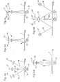
- FIG. 4 a to 4 e schematically show further arrangements of the photodiode line scanner in relation to the moving web 1 and lamps.
- the mechanical propulsion device for the web 1 is in each case similar to that shown in FIG. 1.
- FIG. 4a shows the case in which a part of the web surface onto which a light beam falls is illuminated by a single lamp 6 ′, which is delimited by the slit diaphragm 14.
- This light bundle in turn generates three light bundles 16, 17, 18 to be viewed, of which 16 and 18 contain scattered light, while the bundle 17 contains the directly transmitted light. Accordingly, the bundle 17 is damped with a gray filter 15 '.
- line scanners 20, 21, 22 the intensity signals of the light falling on them are picked up and fed to an amplifier and addition circuit, as can be seen from FIG. 1.
- the shift registers are not necessary because all signals are generated at the same time.
- FIG. 4b shows a variant in which a partial area x of the web 1 passes through the measuring areas illuminated by a single lamp 6 'one after the other.
- the light emerging from this measuring range is detected by a scattering lens 10 'and fed to the line scanners 20-22.
- a color filter 15 is connected in front of the area reached first. With such color filters, for example, color deviations can be detected more easily.
- FIG. 4c works in a similar arrangement to FIG. 4b, but there is no scattering lens, but rather a system of semi-transparent mirrors 50, 51, on which the light is partially reflected in each case and is supplied to correspondingly arranged line scanners 20-22.
- the middle one Beams of light upstream of a gray filter 15 '.
- FIG. 4d shows an arrangement in which mirrors mounted on the side reflect the light bundles emanating from a single lamp 6 ', which are then focused on the line scanners 20-22 with the aid of a scattering lens optics.
- FIG. 4e shows an arrangement in which partially passing light (bundle 17) and partially reflecting light (bundle 16, 18) are used.
- a bundle 17 which passes directly through the path is produced, in the path of which two polarization filters 52 a and 52 b are placed, so that the polarization planes are perpendicular to one another.
- these polarization filters 52 a, b accordingly, light rotations can be observed while passing through the textile web 1.
- the reflecting light from the bundles 16, 18 can of course also be passed through polarizing filters, as is known from optics, mirrored light is polarized so that deviations become visible through polarizing filters
- a converging lens 10 focuses the light beams on the line scanners 20, 21, 22.
- Figures 5a and 5b relate to arrangements for controlling the light intensity of a lamp 6 '.
- the textile web 1 is pulled under the measuring arrangement by the two drive rollers 2, 2 '.
- the textile web drives the photodisk 4, which, as already explained, makes the length coordinates and the speed of the material measurable.
- the photodisk thus makes it possible to completely dispense with labeling the material, for example with magnetic spots or the like.
- the point of the material designated x passes through a glass plate 41, under which the lamp 6 'is arranged.
- the lamp 6 ' can be changed in its luminous flux by a circuit known per se. For this purpose, coming from an amplifier 43 is shown on line 42.
- the luminous flux of the lamp is essentially controlled by the belt speed determined by the photodisk 4.
- a line 44 from the photodisk is provided for this purpose.
- the light rays passing through the web 1 are bundled onto the sensors of the line scanner 20.
- two measuring areas with the associated objectives 10, 11 are arranged across the web 1. These measuring ranges must not overlap at their edges. This exact alignment is very difficult to achieve mechanically, since it is only a fraction of a millimeter. An overlapping area 47 is therefore accepted.
- sensors which receive a light signal of the same measuring range but belong to different line scanners are each switched so that each point is only taken into account once. This results in 20 edge areas in the line scanner, which comprise “switched-off” sensors. These areas are identified by 47 ', 47 ".
- each lamp can be controlled individually, for example in the embodiment according to FIG.
- a further method variant (cf. FIG. 6) consists in the possibility of measuring a stationary or moving reference material web 60 under a specially arranged lens 61 with a line scanner 62.
- the signals run into the discriminator circuit 30 via a preamplifier 63.
- the signal can be used, for example, to serve the common video signal as a comparison signal, so that textiles with patterns can also be examined.
- the additional lens with pattern can also be used to generate a reference signal to compensate for possible optical deviations and errors in the optical system.
Abstract
Description
Die Erfindung bezieht sich auf ein Verfahren zum Beschauen einer reflektierenden und/oder transparenten, sich bewegenden Bahn, insbesondere aus textilem Material, mit wenigstens einer die Bahnoberfläche beleuchtenden Lichtquelle, mit in Reihe quer zur Bahn angeordneten photoelektrischen Sensoren, die in Abstand von der Bahn angeordnet sind und das reflektierte oder durchfallende Licht aufnehmen und entsprechend der Intensität des auf sie fallenden Lichtes ein elektrisches Signal erzeugen, das verstärkt wird und in ein elektrisches Netzwerk eingespeist wird, welches das Signal anhand von gegebenen Fehlerkriterien verarbeitet.The invention relates to a method for viewing a reflecting and / or transparent, moving web, in particular of textile material, with at least one light source illuminating the web surface, with photoelectric sensors arranged in a row transverse to the web and arranged at a distance from the web are and receive the reflected or transmitted light and generate an electrical signal according to the intensity of the light falling on them, which is amplified and fed into an electrical network which processes the signal based on given error criteria.
Aus der Patentliteratur sind zahlreiche Löstungsvorschläge für eine opto-elektronische Untersuchung eines sich bewegenden bahnförmigen Materials bekannt. Insbesondere für die Photo- und Papierindustrie sind Vorrichtungen bekannt, die mit Hilfe eines Scanning-Prinzips die Oberfläche der Bahn laufend abtasten, wobei die sich ergebenden elektrischen Signale der photoelektrischen Sensoren durch ein elektrisches Netzwerk nach bestimmten Kriterien aufgearbeitet werden. Soweit ersichtlich, ist jedoch keine dieser bekannten Vorrichtungen geeignet, bei der Untersuchung von textilem Material eingesetzt zu werden. Die Untersuchungen zeigen, daß textiles Material einen relativ hohen Rauschpegel erzeugt, so daß das Signal-Rausch-Verhältnis nur sehr klein ist und daher sehr schwer analysiert oder bestimmten Fehlerkriterien zugeordnet werden kann. So ist beispielsweise aus der DE-PS 1 917 877 ein Verfahren und eine Vorrichtung der eingangs genannten Art bekannt, bei der sich quer über die Bahnbreite eine Reihe von photoelektrischen Wandlern erstreckt, die von der Materialbahn reflektiertes Licht aufnehmen. Die Lichtquelle ist dabei neben dem Rand der Materialbahn angeordnet, so daß sie einen schmalen Lichtstrahl quer zur Bahnbreite und parallel zur Bahnoberfläche zwischen dieser und der Wandlerreihe ausstrahlt. Diese Vorrichtung kann zwar neben Löchern und groben Oberflächenfeern auch erhabene Fehler ermitteln; es bleibt jedoch das Problem, daß diese Vorrichtung ein für textile Materialien zu niedriges Signal-Rausch-Verhältnis entwickelt, so daß die Verwendung des bekannten Verfahrens bzw. der bekannten Vorrichtung sich als unmöglich erweist.Numerous proposed solutions for an opto-electronic examination of a moving web-like material are known from the patent literature. Devices are known in particular for the photo and paper industry which continuously scan the surface of the web with the aid of a scanning principle, the resulting electrical signals from the photoelectric sensors being processed by an electrical network according to certain criteria. As far as can be seen, however, none of these known devices is suitable for use in the examination of textile material to become. The investigations show that textile material generates a relatively high noise level, so that the signal-to-noise ratio is only very small and is therefore very difficult to analyze or assign to certain error criteria. For example, DE-PS 1 917 877 discloses a method and a device of the type mentioned at the outset, in which a series of photoelectric transducers extends across the width of the web and absorb light reflected from the web of material. The light source is arranged next to the edge of the material web so that it emits a narrow beam of light transverse to the web width and parallel to the web surface between this and the row of transducers. In addition to holes and coarse surface pits, this device can also detect raised defects; however, the problem remains that this device develops a signal-to-noise ratio which is too low for textile materials, so that the use of the known method or the known device proves to be impossible.
Es stellt sich damit die Aufgabe, ein Verfahren zum Beschauen einer sich bewegenden Bahn zu finden, das vom Prinzip her ein hohes Signal-Rausch-Verhältnis ermöglicht, so daß eine sichere Fehlerfeststellung nicht nur dem Vorhanden-sein nach, sondern auch nach Art der Fehler (beispielsweise Fadenverdünnung oder -verdichtung) möglich ist, DAbei soll das Verfahren sich zwar elektronischer Mittel bedienen; die Fehlerauffindung und die Erhöhung des Signal-Rausch-Verhältnisses sollen aber nicht allein auf einer elektronischen Rauschunterdrückung beruhen.It is therefore the task of finding a method for observing a moving web which, in principle, enables a high signal-to-noise ratio, so that reliable fault detection is not only based on the presence but also on the type of the fault (for example thread thinning or thickening) is possible, although the process should use electronic means; however, the fault location and the increase in the signal-to-noise ratio should not be based solely on electronic noise suppression.
Diese Aufgaben werden für ein Verfahren der eingangs genannten Art gelöst, bei dem dieselben Stellen der sich bewegenden Bahn während des Durchlaufens gleichzeitig oder nacheinander unter verschiedenen Blickwinkeln betrachtet werden, wobei die beobachtete Lichtintensität bei Einhaltung des ersten Blickwinkels von einer ersten Reihe optischer Sensoren, die Lichtintensität bei Einhaltung des zweiten Blickwinkels von einer zweiten Reihe Sensoren usw. bis zur n-ten Sensorenreihe erfaßt werden. Bei der Verfahrensvariante, bei der dieselben Stellen der sich bewegenden Bahn während des Durchlaufens nacheinander betrachtet werden, werden die Ausgänge ,der ersten bis (n-1)-ten Sensorenreihe mit je einem Verschieberegister gekoppelt, in dem eine Sequenz von analogen Signalen einer Sensorenreihe zeitverschieblich. gespeichert wird, so daß in einem Vergleichskreis, dem alle Sensorenreihen ihre Signale zuführen, diese Signale synoptisch vergleichbar sind. Jedes Signal wird demnach als "Grauwert" ermittelt, also nicht nur als ein Hell-Dunkel-Raster verarbeitet.These objects are achieved for a method of the type mentioned in the introduction, in which the same points on the moving web are simultaneously or in succession from different angles during the passage are sought, whereby the observed light intensity when the first viewing angle is observed by a first row of optical sensors, the light intensity when the second viewing angle is observed by a second row of sensors, etc. up to the nth row of sensors. In the case of the method variant, in which the same points on the moving web are considered one after the other, the outputs of the first to (n-1) th row of sensors are each coupled to a shift register in which a sequence of analog signals from a row of sensors is time-shiftable . is stored, so that these signals are synoptically comparable in a comparison circuit to which all sensor rows supply their signals. Each signal is therefore determined as a "gray value", that is, it is not only processed as a light-dark grid.
Bei dem Verfahren gemäß Erfindung ist neu, daß bei entsprechender Abstimmung von Geschwindigkeit der Bahn und Taktzeit der optischen Aufnahmefolge ein sehr dichtes Raster von Untersuchungspunkten auf der Bahn erzeugt werden kann, wobei dieselbe Stelle jeweils unter mehreren Blickwinkeln betrachtet wird. Bei aufeinanderfolgender Betrachtung sorgen Analog-Schieberegister dafür, daß die Signalsequenzen während des Vorrückens der Bahn zum nächsten Untersuchungspunkt zur Verfügung stehen, so daß die entsprechenden Signal-Additions- oder Subtraktionsvorgänge in der zur Verfügung stehenden Zeit durchgeführt werden können.What is new in the method according to the invention is that with a corresponding coordination of the speed of the web and the cycle time of the optical recording sequence, a very dense grid of examination points can be generated on the web, the same point being viewed from several angles in each case. When viewed in succession, analog shift registers ensure that the signal sequences are available as the web advances to the next examination point, so that the corresponding signal addition or subtraction processes can be carried out in the time available.
Dieses Verfahren unterscheidet sich auch wesentlich von dem bekannten Signal-Additionsverfahren, die zur Erhöhung des Signal-Rausch-Verhältnisses eine Addition verschiedener Meßdurchläufe vornehmen und mit einem Referenzwert vergleichen. Durch die Betrachtung unter verschiedenen Blickwinkeln, insbesondere bei Messung des durchfallenden Lichtes, ergeben sich ausgezeichnete Signalpegel, die es, wie die Erfahrung erweist, erlauben, insbesondere textiles Material nicht nur nach dem Vorhandensein der Fehler, sondern auch nach Fehlerarten zu untersuchen. Daraus folgt, daß Materialien, bei denen von der Oberflächenbeschaffenheit her das Signal-Rausch-Verhältnis größer ist, selbstverständlich auch untersucht werden können. Als Beispiele seien genannt: Papierbahnen mit Löchern oder Verschmutzungen, Walzbleche, unbelichtete Filme und dergleichen.This method also differs significantly from the known signal addition method which, in order to increase the signal-to-noise ratio, carry out an addition of different measurement runs and compare it with a reference value. Viewing from different angles, especially when measuring the transmitted light, results in excellent ones Signal levels which, as experience has shown, allow textile material in particular to be examined not only for the presence of the defects, but also for the types of defects. From this it follows that materials in which the signal-to-noise ratio is greater in terms of surface quality can of course also be examined. Examples include: paper webs with holes or soiling, rolled sheets, unexposed films and the like.
Neben der Untersuchung des durchfallenden Lichtes ist es auch möglich, durch entsprechende Veränderung der optischen Anordnung reflektiertes Licht zu untersuchen. Das Verfahren ist dabei in seinen Grundzügen gleich. Hierbei kann von einer Anordnung ausgegangen werden, bei der eine Lichtquelle oberhalb des zu untersuchenden Materials angeordnet ist und beispielsweise durch Spiegel mehrere Lichtbündel erzeugt werden. Dieselbe Stelle des Materials kann folglich gleichzeitig auch unter Reflektions- und Transparenzbedingungen untersucht werden.In addition to examining the light passing through, it is also possible to examine reflected light by changing the optical arrangement accordingly. The process is basically the same. An arrangement can be assumed here in which a light source is arranged above the material to be examined and, for example, several light beams are generated by mirrors. The same point on the material can therefore also be examined simultaneously under reflection and transparency conditions.
Ein weiterer, überraschender Vorteil des vorliegenden Verfahrens ist, daß jeder der den einzelnen Blickwinkeln zugeordneten Lichtbündeln in seiner spektralen Zusammensetzung abgewandelt oder in seiner-Schwingungsebene (Polarisationsebene) geändert und untersucht werden kann. Dies kann beispielsweise durch Auswahl verschiedener Lampen mit verschiedenen Spektren, insbesondere Gasentladungslampen, geschehen. Es ist auch möglich, Polarisations- und Farbfilter in den Strahlengang einzusetzen.Another surprising advantage of the present method is that each of the light bundles assigned to the individual viewing angles can be modified in its spectral composition or changed and examined in its vibration level (polarization level). This can be done, for example, by selecting different lamps with different spectra, in particular gas discharge lamps. It is also possible to use polarization and color filters in the beam path.
Geschwindigkeit und Längenkoordinaten der durchlaufenden Bahn werden mittels einer Fotodisk erfaßt, welche mit Der Bahn am Rande angetrieben rotiert und die abgelaufene Länge und/oder Geschwindigkeit der Bahn erfaßt, wobei durch Anzahl der abgegebenen Impulse pro Zeiteinheit sehr genau die abgelaufene Bahnlänge oder die Geschwindigkeit der Bahn erfaßt wird. Bei einer Fotodisk handelt es sich um einen bekannten Analog-DigitalWandler, der den Umdrehungswinkel einer in ihrer Umfangslänge bekannten Walze digital erfaßt, wobei die Zahl der abgegebenen Impulse ein Maß für Weg und Geschwindigkeit ergeben. Die Frequenz der von der Fotodisk ausgehenden Impulsfolge kann weiterhin dazu verwendet werden, die Intensität der die Bahnoberfläche beleuchtenden Lichtquellen zu steuern. Es ist evident, daß bei hoher Bahngeschwindigkeit eine entsprechend höhere Lichtintensität zur Verfügung stehen muß, um ausreichend große Signale zu erzeugen.The speed and length coordinates of the continuous path are recorded by means of a photodisk, which rotates with the web driven at the edge and detects the length and / or speed of the path, the number of pulses emitted per unit of time very precisely the length of the path or the length speed of the train is detected. A photodisk is a known analog-digital converter which digitally detects the angle of rotation of a roller known in its circumferential length, the number of pulses emitted giving a measure of distance and speed. The frequency of the pulse train emanating from the photodisk can also be used to control the intensity of the light sources illuminating the web surface. It is evident that a correspondingly higher light intensity must be available at high web speeds in order to generate sufficiently large signals.
Für die Auswertung der Signale.ist ein den photoelektrischen Sensoren nachgeschalteter.Diskriminatorkreis erforderlich. Insbesondere zur Untersuchung von Textilien auf Fehlstellen, wie Fadenverdichtungen und -verdünnungen, wird die Signalsequenz der ersten Sensorenreihe synoptisch den Signalen der zweiten Sensorenreihe zuaddiert, wobei sich ein erstes Additionssignal ergibt, wird die Signalsequenz der zweiten Sensorenreihe synoptisch dem ersten Additionssignal zuaddiert, wobei sich ein zweites Additionssignal ergibt, wird die Signalsequenz der dritten Sensorenreihe synoptisch dem zweiten Additionssignal zuaddiert, so daß sich ein drittes Additionssignal ergibt, usw., und wird das n-te Additionssignal, d. h. das gemeinsame Videosignal daraufhin untersucht, ob es bestimmten Fehlerkriterien genügt. Unter "Addition" soll auch eine Addition mit negativem Vorzeichen verstanden werden. Dies gilt insbesondere für den Fall, daß Signale sowohl aus Tranzparenz- als auch aus Reflektionsvorgängen stammen. Eine Fadenverdünnung beispielsweise ergibt ein starkes Signal bei Transparenz, dagegen ein schwaches bei Reflektion, Werden bei einem Meßvorgang daher in diesem Sinne "gemischte" Signale verarbeitet, so müssen diese voneinander subtrahiert werden.A discriminator circuit downstream of the photoelectric sensors is required for the evaluation of the signals. In particular for examining textiles for defects, such as thread densification and thinning, the signal sequence of the first row of sensors is synoptically added to the signals of the second row of sensors, resulting in a first addition signal, the signal sequence of the second row of sensors is synoptically added to the first addition signal, with a results in the second addition signal, the signal sequence of the third row of sensors is synoptically added to the second addition signal, so that a third addition signal results, etc., and the nth addition signal, i. H. the common video signal then examines whether it meets certain error criteria. "Addition" should also be understood to mean an addition with a negative sign. This applies in particular to the case that signals originate from both transparency and reflection processes. A thread thinning, for example, gives a strong signal with transparency, but a weak signal with reflection. If "mixed" signals are processed in this sense during a measurement process, they must be subtracted from each other.
Die Gestalt und Amplitude des Videosignals unterscheiden sich charakteristisch dann, wenn Abweichungen von einer gegebenen Normalverteilung gegeben sind. Die Abweichungen können beispielsweise durch Inaugenscheinnahme des erzeugten Videosignals untersucht werden. Ein elektronisches Auswerteverfahren ist beispielsweise in der DE-AS 2 621 109 beschrieben.The shape and amplitude of the video signal differ characteristically when there are deviations from a given normal distribution. The deviations can be examined, for example, by inspecting the generated video signal. An electronic evaluation method is described, for example, in D E -AS 2 621 109.
Die Beschauvorrichtung zur Durchführung des Verfahrens besitzt wenigstens zwei Reihen von photoelektrischen Sensoren, die in Bahnlaufrichtung hintereinander angeordnet sind. Mit Hilfe einer optischen Anordnung wird durchfallendes oder reflektiertes Licht zweier-verschiedener, eventuell weiterer,.gleichzeitig oder nacheinander durchlaufener Stellen mit der sich bewegenden Bahn gebündelt auf die lichtempfindliche Fläche mehrerer Sensorenreihen geworfen. Wenn auch grundsätzlich angestrebt wird, nur wenige photoelektrische Sensoren quer zur Bahn anzuordnen, so ist doch wegen des Erfordernisses einer erhöhten Informations- und Überwachungsdichte erforderlich, daß entsprechend viele Sensoren vorhanden sind. Je geringer die Zahl der Sensoren auf einer bestimmten Breite, um so ungenauer ist die Auflösung.The viewing device for carrying out the method has at least two rows of photoelectric sensors which are arranged one behind the other in the web running direction. With the help of an optical arrangement, falling or reflected light from two different, possibly further, points passed through simultaneously or in succession are thrown together with the moving web onto the light-sensitive surface of several sensor rows. Even if the basic aim is to arrange only a few photoelectric sensors across the web, it is necessary because of the requirement for an increased information and monitoring density that a correspondingly large number of sensors are present. The smaller the number of sensors over a certain width, the less precise the resolution.
Es wird weiterhin vorgeschlagen, daß n (vorzugsweise ist n 1 bis 3) stabförmige Lichtquellen in paralleler Anordnung in Laufrichtung hintereinander unterhalb und/ oder oberhalb der bewegten Bahn angeordnet sind, und daß die von den n Lampen ausgehenden, durch die Bahn fallenden oder von ihr reflektierten n Lichtbündel jeweils, z. B. durch eine Sammellinse, auf die zugeordneten n Sensorenreihen fokussiert werden. Dabei wird vorzugsweise je eine Sensorenreihe durch einen Photodioden-Linienscanner mit hoher Verdichtung der photoelektrischen Sensoren gebildet. Derartige Linienscanner werden beispielsweise von der Firma Reticon Corporation, Mountain View, USA, vertrieben. Die Reticon-Linienscanner besitzen eine Photodioden-Anordnung, bei der beispielsweise 1.024 Elemente mit jeweils 1/1000 Zoll Abstand (0,0254 mm) auf einem Band angeordnet sind. Bei Verwendung einer entsprechenden fokussierenden Optik kann eine Beobachtungsbreite von ca. 5 - 15 cm auf einen solchen Linienscanner gebracht und ausgewertet werden.It is further proposed that n (preferably n is 1 to 3) rod-shaped light sources in a parallel arrangement in the running direction are arranged one behind the other and / or above the moving path, and that those emanating from the n lamps, falling through the path or from it reflected n light beams each, e.g. B. be focused by a converging lens on the assigned n rows of sensors. In this case, one row of sensors is preferably formed by a photodiode line scanner with high compression of the photoelectric sensors. Such line scanners are sold, for example, by Reticon Corporation, Mountain View, USA. The Reticon line scanners have a photodiode arrangement in which, for example, 1,024 elements are arranged on a band, each 1/1000 inch apart (0.0254 mm). When using appropriate focusing optics, an observation width of approx. 5 - 15 cm can be brought to such a line scanner and evaluated.
Zur Erfassung großer Bahnbreiten werden über die Bahnbreite mehrere Sensorenreihen-Gruppen nebeneinander angeornet, denen jeweils getrennte optische Fokussierungssysteme zugeordnet sind.To detect large path widths, several sensor row groups are arranged side by side over the path width, each of which is assigned separate optical focusing systems.
Weitere Eigenschaften und Merkmale ergeben sich aus der nachfolgenden Beschreibung einiger ausgewählter Ausführungsbeispiele, die in der Zeichnung dargestellt sind. Die Figuren der Zeichnung zeigen:
Figur 1 in schematischer Darstellung die Meßanordnung mit dem nachgeschalteten Verschieberegister-Additionskreis;Figur 2 eine Textilanordnung (Gewebe) und das sich daraus ergebende gemeinsame Videosignal;Figur 3 einen Schnitt durch einen Meßkopf mit Objektiv;- Figuren 4a bis 4e verschiedene andere Meßanordnungen in schematischer Darstellung;
- Figuren 5a, b eine Anordnung der Intensitätssteuerung;
Figur 6 eine Anordnung ähnlich wie inFigur 1, jedoch mit einem Referenzobjektiv und -muster.
- Figure 1 is a schematic representation of the measuring arrangement with the downstream shift register addition circuit;
- Figure 2 shows a textile arrangement (fabric) and the resulting common video signal;
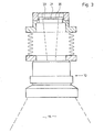
- Figure 3 shows a section through a measuring head with lens;
- Figures 4a to 4e various other measuring arrangements in a schematic representation;
- Figures 5a, b an arrangement of the intensity control;
- Figure 6 shows an arrangement similar to that in Figure 1, but with a reference lens and pattern.
In Figur 1 ist schematisch eine Vorrichtung zum Feststellen von Fehlern in einer ersten Ausführungsform dargestellt. Eine zu überwachende Textilbahn 1, die in Richtung des Pfeils mit Hilfe eines Rollenantriebes 2 von einer Vorratsrolle 3 abgezogen wird, passiert.zunächst eine Registriereinheit (Photodisk) 4. Die Photodisk hat die Aufgabe, mit einer Reibrolle die Bahnposition (abgelaufene Länge) und indirekt die Bahngeschwindigkeit festzustellen, so daß sowohl die Linienkoordinate als auch die Geschwindigkeit festlegbar sind. Anschließend überläuft die Bahn eine Lampenstation 5, die im wesentlichen aus drei, über die gesamte Bahnbreite parallel ausgerichteten, in Längsrichtung hintereinander angeordneten Glühwendellampen 6, 7, 8 besteht. Die Lampen sind beispielsweise bekannte 60 W-Gleichstrom-Drahtwendellampen, die einen Lichtstrom erzeugen, von dem ein ausreichender Teil durch, die teiltransparente Textilbahn im Bereich des zu untersuchenden Abschnittes x hindurchtritt. Entsprechend der Qualität und Dichte des zu untersuchenden Textilmaterials müssen eventuell die Lampen variiert werden. Wesentlich ist, daß die Lampen einen konstanten Lichtstrom abgeben. Übliche Leuchtstofflampen mit Edelgasfüllung, die im Wechselstrombetrieb arbeiten, sind deshalb nicht geeignet.In Figure 1, a device for detecting errors is shown schematically in a first embodiment. A
Der Abstand der Lampen untereinander, gemessen als Abstand der einander zugewandten Seitenflächen, liegt bei etwa 3 cm. Der Abstand von der Bahnebene liegt bei etwa 2 cm; er sollte zur Erhöhung der Lichtausbeute möglichst gering sein. Oberhalb der Lampen sind (nicht dargestellte) Schlitzblenden angeordnet, die jeweils ein schmales Lichtbündel 16 - 18 erzeugen. Außerdem können Grau;, Polarisations- und/oder Farbfilter in die Lichtbündel vor oder hinter der Bahn eingebaut sein.The distance between the lamps, measured as the distance between the facing side surfaces, is about 3 cm. The distance from the web plane is about 2 cm; it should be as low as possible to increase the light output. Slit diaphragms (not shown) are arranged above the lamps, each of which generates a narrow light beam 16-18. In addition, gray, polarization and / or color filters can be installed in the light bundles in front of or behind the web.
Über die Bahn im Bereiche der Lampenanordnung 5 sind drei fokussierende Objektive 10, 11, 12 über die Bahnbreite verteilt angeordnet, so daß jedes der Objektive aufgrund seiner Brennweite einen Teil der Lichtbündel 16 - 18 erfaßt und fokussiert, die von je einer der Lampen 6 - 7 ausgehen. Dabei wird von der mittleren Lampe 7 in erster Linie das direkte, von den anderen Lampen jedoch das an der Textilbahn gestreute Licht erfaßt. Meßtechnisch bedeutsam ist, daß bei der gewählten Meßmethode, die mit Streulicht arbeitet, eine Reflektion innerhalb der Textilbahn auftreten kann, z. B. an fehlerhaften Fäden oder an sich in der Bahn befindlichen Fremdkörpern, so daß diese Fehler besonders gut erfaßt werden. Durch das Durchlaufen dreier verschiedener Blickwinkel wird im allgemeinen jede als Fehler zu definierende Veränderung erfaßt.Three focussing
Die fokussierten Abbildungen der Bahnbereiche werden auf je einen 1.024 Bit-Photodioden-Linienscanner 20, 21, 22 projiziert. Die drei jedem Objektiv zugeordneten Linienscanner haben einen Sensorteil von 25,4 mm (1 Zoll) Länge, auf dem 1.024 durch ein Quarzfenster abgeschirmte, elektrisch voneinander getrennte Photodioden nebeneinander in einer Linie angeordnet sind. Derartige Linienscanner sind an sich bekannt (z. B. RETICON RL 1.024 B). Teilt man, wie im Ausführungsbeispiel vorgeschlagen, daher die gesamte Breite der Textilbahn in drei Überwachungsbereiche auf, so sind bei einer gewissen Überlappung jeder Lampe ca. 3.000 Meßpunkte zugeordnet. Jedes einzelne Photodiodensignal gibt daher einen relativ eng begrenzten Bereich wieder, Beispielsweise werden Meßanordnungen gewählt, so daß eine Bahnbreite von 1 mm von 10 Photodioden (Meßpunkten) erfaßt wird. Die maximale spektrale Empfindlichkeit derartiger Linienscanner liegt im Bereich von 6.000 - 800 nm.The focused images of the web areas are each projected onto a 1024 bit
Das Video-Ausgangssignal des Linienscanners ist eine Impulsfolge von 1.024 Ladungen, die von einem Videoausgang abgerufen werden. Da die Ausgangssignale nur als kapazitive Ladungen abgerufen werden können, wird jedem Linienscanner 20, 21, 22 je ein Vorverstärker 23, 24, 25 nachgeschaltet. Die Ausgänge der Vorverstärker 23 - 25 sind wie folgt verbunden: Ausgang des Vorverstärkers 23 mit dem Eingang eines ersten Schieberegisters 26, dessen Ausgang mit dem Eingang eines ersten Differenzverstärkers verbunden ist; der Ausgang des Vorverstärkers 24 ist mit dem.Eingang des ersten Differenzverstärkers 27 verbunden; der Ausgang des Vorverstärkers 25 ist mit dem Eingang eines zweiten Differenzverstärkers 29 verbunden; der Ausgang des Differenzverstärkers 27 ist an den Eingäng eines Schieberegisters 28 angeschlossen, dessen Ausgang mit dem Eingang des zweiten Differenzverstärkers 29 verbunden ist. Das Ausgangssignal des Differenzverstärkers 29 ist über eine Verbindungsleitung 19 mit einem Diskriminatorkreis für das Videosignal verbunden. Am Ausgang des zweiten Differenzverstärkers 29 entsteht nämlich ein "gemeinsames Videosignal", dessen elektronische Analyse durch einen Diskriminatorkreis 30 durchgeführt wird. Statt die Vorverstärker-Ausgänge direkt zu schalten, können die Signale auch über Inverter 23', 24', 25' geleitet werden, die jeweils die negative Signalspannung erzeugen. über Wahlschalter 23", 24", 25" können demnach auch die Signale der Linienscanner subtrahiert werden.The video output signal of the line scanner is a pulse sequence of 1,024 charges, which are called up from a video output. Since the output signals can only be called up as capacitive charges each
Figur 2 zeigt eine Signalfolge, die sich bei Überwachung eines textilen Materials, beispielsweise eines Nesselgewebes ergibt. Die Betrachtung erfolgt anhand einer schematisierten Intensitätskurve. Bei A ist eine Reihe von Kettfäden 45 des Nesselgewebes dargestellt, die nacheinander als Videosignal erscheinen. Dabei ist davon ausgegangen, daß das zugehörige addierte, synoptisch betrachtete Videosignal dreier, einer bestimmten Linie zugeordneten Photodioden (Sensoren) durch eine Kurve B wiedergegeben wird, die durch entsprechenden Abgriff erzielt wird. Die Kettstruktur gemäß A ist in fünf Zonen unterteilt. Die Zonen 1, 3 und 5 enthalten normale Abstände der Kettfäden, während die Zone 2 eine Verdünnung und die Zone 4 eine Verdichtung darstellen.FIG. 2 shows a signal sequence which results when monitoring a textile material, for example a nettle fabric. The consideration is based on a schematic intensity curve. At A, a series of
Bei einer einzigen Betrachtungsart, z. B. nur Reflektion-oder nur Transparenzmessungen, werden die ankommenden Signale synoptisch addiert. Bei Verwendung von Invertern 23', 24' bzw. 25' oder eines Schieberegisters, bei dem Vorzeichenumkehr eintritt (z. B. Typ Fairchild, CCD 32 A) sind daher die Signale jeweils nochmals in ihrem Vorzeichen zu ändern. Das bedeutet, daß die von einer bestimmten Stelle der Bahn herrührenden Signale addiert werden. Werden gemischt erzeugte Signale betrachtet, also beispielsweise ein durch Reflektion und zwei durch Transparenz erzeugte Signale, so sind die Signale einer bestimmten Art jeweils mit dem Vorzeichen + bzw. das der anderen Art mit dem Vorzeichen - zu versehen.With a single view, e.g. B. only reflection or only transparency measurements, the incoming signals are added synoptically. When using inverters 23 ', 24' or 25 'or a shift register in which sign reversal occurs (e.g. type Fairchild, CC D 32 A ), the signals must be changed again in each case. This means that the signals coming from a certain point on the path are added. If signals generated in a mixed manner are considered, for example one signal generated by reflection and two signals generated by transparency, the signals of a certain type are to be provided with the + sign and those of the other type with the - sign.
Die eigentliche Verarbeitung der Signale kann durch Inaugenscheinnahme oder durch bekannte Diskriminatorkreise erfolgen. Dabei ist zu berücksichtigen, daß sowohl die Amplitude'als auch der sich durch Integration ergebende-Wert der Kurve gemäß Figur 2 B charakteristische Unterschiede zeigt. Bei einer Fadenverdünnung (Zone 2) ist die Lichtintensität und damit das Integral größer, bei einer Fadenverdichtung ergibt sich ein entsprechend kleineres, im Integrationswert geringeres, Signal (Zonen 3, 4).The actual processing of the signals can be done by inspection or by known discriminator groups. It must be taken into account that both the amplitude and the value of the curve resulting from integration according to FIG. 2B show characteristic differences. With a thread thinning (zone 2) the light intensity and thus the integral is greater, with a thread thickening there is a correspondingly smaller signal (
Figur 3 zeigt Details der optischen Anordnung, teilweise geschnitten. Ein Lichtbündel 16 fällt in ein an sich bekanntes Weitwinkelobjektiv 10 ein, beispielsweise ein 11-Linsen-Objektiv, das im Handel käuflich erhältlich ist. Das Lichtbündel wird fokussiert und scharf eingestellt auf die Ebene der Linienscanner 20 - 22, die im Fokalbereich des Objektives im Inneren einer Kappe angeordnet sind. Die Objektive sind an einer Befestigungsleiste 13 angebracht.Figure 3 shows details of the optical arrangement, partially in section. A
Die Figuren 4 a bis 4 e zeigen schematisch weitere Anordnungen der Photodioden-Linienscanner in Bezug auf die sich bewegende Bahn 1 und Lampen. Dabei ist die mechanische Vortriebsvorrichtung für die Bahn 1 jeweils ähnlich wie in Figur 1 dargestellt.Figures 4 a to 4 e schematically show further arrangements of the photodiode line scanner in relation to the moving
Figur 4a zeigt den Fall, daß von einer einzigen Lampe 6' ein Teil der Bahnfläche beleuchtet wird, auf die ein Lichtbündel fällt,-das durch die Schlitzblende 14 begrenzt ist. Dieses Lichtbündel erzeugt wiederum drei zu betrachtende Lichtbündel 16, 17, 18, von denen 16 und 18 Streulicht beinhalten, während das Bündel 17 das direkt durchgestrahlte Licht enthält. Entsprechend ist das Bündel 17 mit einem Graufilter 15' gedämpft. Mit Hilfe der Linienscanner 20, 21, 22 werden die Intensitätssignale des auf sie fallenden Lichtes aufge, nommen und einem Verstärker- und Additionskreis zugeführt, wie dies aus Figur 1 ersichtlich ist. Allerdings sind dabei die Verschieberegister nicht erforderlich, da alle Signale gleichzeitig anfallen.FIG. 4a shows the case in which a part of the web surface onto which a light beam falls is illuminated by a
Figur 4b zeigt eine Variante, bei der ein Teilbereich x der Bahn 1 nacheinander die von einer einzigen Lampe 6' ausgeleuchteten Meßbereiche durchläuft. Das von diesem Meßbereich ausgehende Licht wird durch eine Streulinse 10' erfaßt und den Linienscannern 20 - 22 zugeführt. Im vorliegenden Falle ist vor den zuerst erreichten Bereich ein Farbfilter 15 geschaltet. Mit derartigen Farbfiltern lassen sich beispielsweise Farbabweichungen leichter erfassen.FIG. 4b shows a variant in which a partial area x of the
Figur 4c arbeitet in einer ähnlichen Anordnung wie Figur 4b, jedoch ist keine Streulinse vorhanden, sondern ein System von halbdurchlässigen Spiegeln 50, 51, an denen das Licht jeweils teilweise reflektiert wird und entsprechend angeordneten Linienscannern 20 - 22 zugeführt wird. Im vorliegenden Falle ist dem mittleren Lichtstrahlbündel ein Graufilter 15' vorgeschaltet.FIG. 4c works in a similar arrangement to FIG. 4b, but there is no scattering lens, but rather a system of
Figur 4d zeigt eine Anordnung, bei der seitlich angebrachte Spiegel die von einer einzigen Lampe 6' ausgehenden Lichtbündel reflektieren, die dann mit Hilfe einer Streulinsen-Optik auf die Linienscanner 20 - 22 fokussiert werden.FIG. 4d shows an arrangement in which mirrors mounted on the side reflect the light bundles emanating from a single lamp 6 ', which are then focused on the line scanners 20-22 with the aid of a scattering lens optics.
Figur 4e stellt eine Anordnung dar, bei der teilweise hindurchtretendes Licht (Bündel 17) und teilweise reflektierendes Licht (Bündel 16, 18) verwendet wird. Mit Hilfe der unterhalb der Bahn angeordneten Lampe 7" wird ein direkt durch die Bahn hindurchtretendes Bündel 17 erzeugt, in dessen Laufbahn zwei Polarisationsfilter 52 a und 52 b gestellt sind, daß die Polarisationsebenen senkrecht zueinander stehen. Mit Hilfe dieser Polarisationsfilter 52 a, b lassen sich demnach Lichtdrehungen während des Durchtretens durch die Textilbahn 1 beobachten. Das reflektierende Licht der Bündel 16, 18 kann selbstverständlich ebenfalls durch Polarisationsfilter geschickt werden; wie aus der Optik bekannt ist, wird gespiegeltes Licht polarisiert, so daß Abweichungen durch Polarisationsfilter sichtbar werden. Mit Hilfe einer Sammellinse 10 werden die Lichtbündel auf die Linienscanner 20, 21., 22 fokussiert.FIG. 4e shows an arrangement in which partially passing light (bundle 17) and partially reflecting light (bundle 16, 18) are used. With the help of the lamp 7 ″ arranged underneath the path, a
Die Figuren 5a und 5b betreffen Anordnungen zur Steuerung der Lichtintensität einer Lampe 6'. Durch die beiden Antriebsrollen 2, 2' wird die Textilbahn 1 unter der Meßanordnung durchgezogen. Dabei treibt die Textilbahn die Photodisk 4 an, die, wie bereits erläutert, die Längenkoordinaten und die Geschwindigkeit des Materials meßbar macht. Die Photodisk ermöglicht es damit, daß auf eine Kennzeichnung des Materials beispielsweise mit Magnetflecken oder dergleichen völlig verzichtet werden kann.Figures 5a and 5b relate to arrangements for controlling the light intensity of a lamp 6 '. The
Die mit x bezeichnete Stelle des Materials gelangt über eine Glasplatte 41, unter der die Lampe 6' angeordnet ist. Die Lampe 6' kann in ihrem Lichtstrom durch eine an sich bekannte Schaltung verändert werden. Hierzu ist an der Leitung 42 von einem Verstärker 43 kommend eingezeichnet. Der Lichtstrom der Lampe wird dabei im wesentlichen gesteuert durch die von der Photodisk 4 festgestellte Bandgeschwindigkeit. Hierzu ist eine Leitung 44 von der Photodisk vorgesehen.The point of the material designated x passes through a
Die durch die Bahn 1 tretenden Lichtstrahlen werden gebündelt auf die Sensoren des Linienscanners 20 geworfen. Wie aus Figur 5b erkennbar ist, sind quer über die Bahn 1 zwei Meßbereiche mit den zugehörigen Objektiven 10, 11 angeordnet. Diese Meßbereiche dürfen sich an ihren Rändern nicht überlappen. Diese genaue Aneinanderreihung ist aber mechanisch sehr schwer zu bewerkstelligen, da es nur um Bruchteile von mm geht. Es wird daher ein überlappender Bereich 47 in Kauf genommen. Um aber trotzdem einen "nahtlosen" Anschluß der Meßbereiche zu erreichen, werden Sensoren, die ein Lichtsignal desselben Meßbereiches erhalten, jedoch verschiedenen Linienscannern angehören, jeweils so geschaltet, daß jede Stelle nur einmal berücksichtigt wird. Dadurch ergeben sich im Linienscanner 20 Randbereiche, die "abgeschaltete" Sensoren umfassen. Diese Bereiche sind mit 47', 47" gekennzeichnet. Da die Signale von diesen Sensoren nicht addiert werden, können sie dazu dienen, auf ihre Intensität überprüft zu werden. Sobald sie eine mittlere, festgelegte Sollintensität über- oder unterschreiten, kann über einen Vorverstärker 46 und einen nachgeschalteten Intensitätsverstärker 43 die Intensität der Lampe 6' ebenfalls verändert werden. Durch den mit zwei Eingängen versehenen Verstärker 43 können damit beide Einflußgrößen, nämlich Bahngeschwindigkeit und natürlicheDicke oder natürlicher Lichtverlust berücksichtigt werden. Da jeder Lampe ein bestimmter Linienscanner zugeordnet ist, kann jede Lampe, beispielsweise bei der Ausführungsform gemäß Figur 1, einzeln gesteuert werden.The light rays passing through the
Insgesamt ergeben sich durch das Verfahren und die zugehörige Vorrichtung überraschende Möglichkeiten, bisher nicht bekannte Auflösungen für bestimmte Textil-Fehler zu ermöglichen.Overall, the method and the associated device offer surprising possibilities for enabling previously unknown resolutions for certain textile defects.
Eine weitere Verfahrensvariante (vgl. Figur 6) besteht in der Möglichkeit, eine stillstehende oder mitlaufende Referenzmaterialbähn 60 unter einem speziell dafür angeordneten Objektiv 61 mit Linienscanner 62 zu messen. Die Signale laufen über einen Vorverstärker 63 in den Diskriminatorschaltkreis 30 ein, Das Signal kann beispielsweise dazu dienen, dem gemeinsamen Videosignal als Vergleichssignal zu dienen, so daß auch Textilien mit Mustern untersucht werden können. Das zusätzliche Objektiv mit Muster kann auch dazu dienen, ein Referenzsignal zur Kompensation eventueller optischer Abweichungen und Fehler im optischen System zu erzeugen.A further method variant (cf. FIG. 6) consists in the possibility of measuring a stationary or moving
Claims (12)
dadurch gekennzeichnet, daß
dieselben Stellen (x) der sich bewegenden Bahn (1) während des Durchlaufes gleichzeitig oder nacheinander unter verschiedenen Blickwinkeln betrachtet werden, wobei die beobachtete Lichtintensität bei Einhaltung des ersten Blickwinkels von der ersten Reihe optischer Sensoren (20), die Lichtintensität bei Einhaltung des zweiten Blickwinkels von der zweiten Reihe der Sensoren (21) usw. bis zur n-ten Sensorenreihe erfaßt werden, und daß bei aufeinanderfolgender Betrachtung die Ausgänge der ersten bis (n-1)ten Sensorenreihe mit je einem Verschieberegister gekoppelt sind, in dem eine Sequenz von analogen Signalen einer Sensorenreihe zeitverschieblich gespeichert wird, so daß in einem Vergleichskreis, dem alle Sensorenreihen ihre Signale zuführen, die Signale synoptisch verglichen werden können.1. A method for viewing a reflective and / or transparent, moving web, in particular made of textile material, with at least one light source illuminating the web surface, with photoelectric sensors arranged in series transverse to the web, which are arranged at a distance from the web and which reflected and / or pick up transmitted light and, in accordance with the intensity of the light falling on it, generate an electrical signal which is amplified and fed into an electrical network which processes the signal on the basis of given error criteria,
characterized in that
the same points (x) of the moving path (1) are viewed simultaneously or successively from different angles during the passage, the observed light intensity from the first row of optical sensors (20) while maintaining the first angle of view, the light intensity when the second angle is observed from the second row of sensors (21) etc. to the n-th row of sensors, and that when viewed in succession, the outputs of the first to (n-1) th row of sensors are each coupled to a shift register in which a sequence of analog Signals of a sensor row is stored in a time-shifting manner, so that the signals can be compared synoptically in a comparison circuit to which all sensor rows supply their signals.
die Signalsequenz der dritten Sensorenreihe synoptisch dem zweiten Additionssignal zuaddiert wird, und ein drittes Additionssignal, d. h. das gemeinsame Videosignal, original und/oder invertiert einem oder mehreren Differenzverstärkern eingegeben wird, die alle Signalspannungswerte oberhalb eines festgelegten Spannungswertes integrieren, wobei der Gestalt und Amplitude des integrierten Spannungswertes ein Kri, terium für die Art der Fehlstellen ist.5. The method according to claim 1, characterized in that, in particular for examining textiles for imperfections such as thread densification, thinning and staining, when considering the web-shaped material, the signal sequence of the first sensor row is added to the signals of the second sensor row synoptically, resulting in a first addition signal, the signal sequence of the first row of sensors is synoptically added to the signals of the second row of sensors, resulting in a first addition signal, the signal sequence of the second row of sensors is synoptically added to the first addition signal and yielding a second addition signal,
the signal sequence of the third row of sensors is synoptically added to the second addition signal, and a third addition signal, ie the common video signal, is input original and / or inverted to one or more differential amplifiers which integrate all signal voltage values above a defined voltage value, the shape and amplitude of the integrated Voltage value is a criterion for the type of defects.
Applications Claiming Priority (2)
| Application Number | Priority Date | Filing Date | Title |
|---|---|---|---|
| DE3043849 | 1980-11-21 | ||
| DE19803043849 DE3043849A1 (en) | 1980-11-21 | 1980-11-21 | METHOD FOR VIEWING A REFLECTIVE AND / OR TRANSPARENT, MOVING TRAIN AND FOAMING MACHINE FOR CARRYING OUT THE METHOD |
Publications (2)
| Publication Number | Publication Date |
|---|---|
| EP0052813A2 true EP0052813A2 (en) | 1982-06-02 |
| EP0052813A3 EP0052813A3 (en) | 1983-09-28 |
Family
ID=6117234
Family Applications (1)
| Application Number | Title | Priority Date | Filing Date |
|---|---|---|---|
| EP81109444A Withdrawn EP0052813A3 (en) | 1980-11-21 | 1981-10-30 | Method for the examination of a moving reflecting or transparent sheet, and device for carrying out said method |
Country Status (2)
| Country | Link |
|---|---|
| EP (1) | EP0052813A3 (en) |
| DE (1) | DE3043849A1 (en) |
Cited By (20)
| Publication number | Priority date | Publication date | Assignee | Title |
|---|---|---|---|---|
| GB2144219A (en) * | 1983-07-16 | 1985-02-27 | Leicester Polytechnic | Inspecting textile products |
| US4637054A (en) * | 1983-11-23 | 1987-01-13 | Kearney & Trecker Marwin Limited | Inspecting articles |
| EP0240610A2 (en) * | 1986-01-08 | 1987-10-14 | Hercules Incorporated | Apparatus and method for sensing multiple parameters of sheet material |
| US4744035A (en) * | 1983-07-16 | 1988-05-10 | National Research Development Corporation | Inspecting textile products |
| DE3639636A1 (en) * | 1986-11-20 | 1988-05-26 | Robert Prof Dr Ing Massen | Automatic inspection of textile webs |
| DE3729804A1 (en) * | 1987-09-05 | 1989-03-16 | Menschner Maschf Johannes | METHOD FOR THE AUTOMATIC DETECTION OF ERRORS IN MOVING TRACKS |
| EP0315697A1 (en) * | 1987-05-27 | 1989-05-17 | Nippon Sheet Glass Co., Ltd. | Discriminative flaw detector for light-transmissive sheet material |
| EP0350680A2 (en) * | 1988-07-11 | 1990-01-17 | Abb Process Automation Inc. | Light source module for sheet inspection system |
| WO1990007707A1 (en) * | 1988-12-27 | 1990-07-12 | Eastman Kodak Company | Control means for web scanning apparatus |
| WO1995034810A1 (en) * | 1994-06-14 | 1995-12-21 | John Heyer Paper Ltd. | Web monitoring for paper machines |
| DE10102557A1 (en) * | 2001-01-20 | 2002-08-01 | Visotec Gmbh | Detection of surface defects or inclusions within sheet material, especially sheet glass using a camera detection system arranged above the glass surface for recording multiple sectional images that can then be compared |
| EP1712897A1 (en) * | 2005-04-12 | 2006-10-18 | Meinan Machinery Works, Inc. | Method of inspecting a broad article |
| DE102006050839B3 (en) * | 2006-10-27 | 2008-02-14 | Fagus-Grecon Greten Gmbh & Co Kg | Device for testing flat material has housing for radiation fan that expands towards radiation detector and that is filled gas tight with gas transparent to radiation |
| CN102296453A (en) * | 2011-06-27 | 2011-12-28 | 张洪 | Cloth inspection device with adjustable height |
| WO2016037735A1 (en) * | 2014-09-08 | 2016-03-17 | Khs Gmbh | Polarisation camera for monitoring conveyor belts |
| EP3101167A3 (en) * | 2015-06-01 | 2017-01-04 | Herbert Kannegiesser GmbH | Method for testing washed or cleaned laundry |
| WO2019150243A1 (en) * | 2018-01-31 | 2019-08-08 | 3M Innovative Properties Company | Virtual camera array for inspection of manufactured webs |
| US11327010B2 (en) | 2018-01-31 | 2022-05-10 | 3M Innovative Properties Company | Infrared light transmission inspection for continuous moving web |
| CN115823412A (en) * | 2022-08-26 | 2023-03-21 | 宁德时代新能源科技股份有限公司 | Detection apparatus, method, computer device, storage medium, and program product |
| US11897977B2 (en) | 2018-01-31 | 2024-02-13 | 3M Innovative Properties Company | Photolabile barbiturate compounds |
Families Citing this family (3)
| Publication number | Priority date | Publication date | Assignee | Title |
|---|---|---|---|---|
| FR2548077B1 (en) * | 1983-06-30 | 1987-03-06 | Gerber Scient Inc | APPARATUS FOR HELPING AN OPERATOR TO SOLVE PROBLEMS POSED BY FAULTS OF FABRICS |
| DE19624905A1 (en) * | 1996-06-21 | 1998-01-08 | L & P Elektroautomatisations G | Piece goods quality control |
| DE102013005489B4 (en) | 2013-04-02 | 2019-06-27 | Capex Invest GmbH | Method and device for the automatic detection of defects in limp bodies |
Citations (9)
| Publication number | Priority date | Publication date | Assignee | Title |
|---|---|---|---|---|
| US3588513A (en) * | 1968-04-08 | 1971-06-28 | Omron Tateisi Electronics Co | Method and apparatus for photoelectric inspection of sheet materials |
| US3786265A (en) * | 1973-02-02 | 1974-01-15 | Lindly Company Inc | Apparatus for detecting defects in continuous traveling material |
| US3812373A (en) * | 1972-07-31 | 1974-05-21 | Nippon Kokan Kk | Method and apparatus for identifying the periodicity of surface defects of strip materials |
| US3824021A (en) * | 1973-06-14 | 1974-07-16 | N Axelrod | Redundant imperfection detection system for materials |
| US3841761A (en) * | 1973-10-24 | 1974-10-15 | Neotec Corp | Method and apparatus for detecting faults in fabric |
| US4005281A (en) * | 1975-05-14 | 1977-01-25 | E. I. Du Pont De Nemours And Company | Defect identification with normalizing of gain function in optical-electrical inspection |
| JPS5288085A (en) * | 1976-01-17 | 1977-07-22 | Canon Inc | Defect detection system |
| US4172666A (en) * | 1976-12-01 | 1979-10-30 | Ferranti Limited | Inspection apparatus |
| EP0008353A1 (en) * | 1978-08-09 | 1980-03-05 | Westinghouse Electric Corporation | Method of detection and classification of flaws on metallic surfaces |
-
1980
- 1980-11-21 DE DE19803043849 patent/DE3043849A1/en not_active Withdrawn
-
1981
- 1981-10-30 EP EP81109444A patent/EP0052813A3/en not_active Withdrawn
Patent Citations (9)
| Publication number | Priority date | Publication date | Assignee | Title |
|---|---|---|---|---|
| US3588513A (en) * | 1968-04-08 | 1971-06-28 | Omron Tateisi Electronics Co | Method and apparatus for photoelectric inspection of sheet materials |
| US3812373A (en) * | 1972-07-31 | 1974-05-21 | Nippon Kokan Kk | Method and apparatus for identifying the periodicity of surface defects of strip materials |
| US3786265A (en) * | 1973-02-02 | 1974-01-15 | Lindly Company Inc | Apparatus for detecting defects in continuous traveling material |
| US3824021A (en) * | 1973-06-14 | 1974-07-16 | N Axelrod | Redundant imperfection detection system for materials |
| US3841761A (en) * | 1973-10-24 | 1974-10-15 | Neotec Corp | Method and apparatus for detecting faults in fabric |
| US4005281A (en) * | 1975-05-14 | 1977-01-25 | E. I. Du Pont De Nemours And Company | Defect identification with normalizing of gain function in optical-electrical inspection |
| JPS5288085A (en) * | 1976-01-17 | 1977-07-22 | Canon Inc | Defect detection system |
| US4172666A (en) * | 1976-12-01 | 1979-10-30 | Ferranti Limited | Inspection apparatus |
| EP0008353A1 (en) * | 1978-08-09 | 1980-03-05 | Westinghouse Electric Corporation | Method of detection and classification of flaws on metallic surfaces |
Non-Patent Citations (1)
| Title |
|---|
| PATENTS ABSTRACTS OF JAPAN, Band 1, Nr. 148, 29. November 1977, Seite 7654E77 & JP-A-52 088 085 (CANON K.K.) (22-07-1977) * |
Cited By (27)
| Publication number | Priority date | Publication date | Assignee | Title |
|---|---|---|---|---|
| GB2144219A (en) * | 1983-07-16 | 1985-02-27 | Leicester Polytechnic | Inspecting textile products |
| US4744035A (en) * | 1983-07-16 | 1988-05-10 | National Research Development Corporation | Inspecting textile products |
| US4637054A (en) * | 1983-11-23 | 1987-01-13 | Kearney & Trecker Marwin Limited | Inspecting articles |
| EP0240610A2 (en) * | 1986-01-08 | 1987-10-14 | Hercules Incorporated | Apparatus and method for sensing multiple parameters of sheet material |
| EP0240610A3 (en) * | 1986-01-08 | 1989-12-20 | Hercules Incorporated | Apparatus and method for sensing multiple parameters of sheet material |
| DE3639636A1 (en) * | 1986-11-20 | 1988-05-26 | Robert Prof Dr Ing Massen | Automatic inspection of textile webs |
| EP0315697A1 (en) * | 1987-05-27 | 1989-05-17 | Nippon Sheet Glass Co., Ltd. | Discriminative flaw detector for light-transmissive sheet material |
| EP0315697A4 (en) * | 1987-05-27 | 1990-10-03 | Nippon Sheet Glass Co., Ltd. | Discriminative flaw detector for light-transmissive sheet material |
| DE3729804A1 (en) * | 1987-09-05 | 1989-03-16 | Menschner Maschf Johannes | METHOD FOR THE AUTOMATIC DETECTION OF ERRORS IN MOVING TRACKS |
| EP0350680A2 (en) * | 1988-07-11 | 1990-01-17 | Abb Process Automation Inc. | Light source module for sheet inspection system |
| EP0350680A3 (en) * | 1988-07-11 | 1991-07-31 | Abb Process Automation Inc. | Light source module for sheet inspection system |
| WO1990007707A1 (en) * | 1988-12-27 | 1990-07-12 | Eastman Kodak Company | Control means for web scanning apparatus |
| WO1995034810A1 (en) * | 1994-06-14 | 1995-12-21 | John Heyer Paper Ltd. | Web monitoring for paper machines |
| US5745365A (en) * | 1994-06-14 | 1998-04-28 | John Heyer Paper Ltd. | Web monitoring for paper machines |
| DE10102557A1 (en) * | 2001-01-20 | 2002-08-01 | Visotec Gmbh | Detection of surface defects or inclusions within sheet material, especially sheet glass using a camera detection system arranged above the glass surface for recording multiple sectional images that can then be compared |
| DE10102557B4 (en) * | 2001-01-20 | 2005-11-17 | Visotec Gmbh | Method and device for checking disk-shaped workpieces for surface or inclusion defects |
| EP1712897A1 (en) * | 2005-04-12 | 2006-10-18 | Meinan Machinery Works, Inc. | Method of inspecting a broad article |
| DE102006050839B3 (en) * | 2006-10-27 | 2008-02-14 | Fagus-Grecon Greten Gmbh & Co Kg | Device for testing flat material has housing for radiation fan that expands towards radiation detector and that is filled gas tight with gas transparent to radiation |
| CN102296453A (en) * | 2011-06-27 | 2011-12-28 | 张洪 | Cloth inspection device with adjustable height |
| WO2016037735A1 (en) * | 2014-09-08 | 2016-03-17 | Khs Gmbh | Polarisation camera for monitoring conveyor belts |
| EP3101167A3 (en) * | 2015-06-01 | 2017-01-04 | Herbert Kannegiesser GmbH | Method for testing washed or cleaned laundry |
| WO2019150243A1 (en) * | 2018-01-31 | 2019-08-08 | 3M Innovative Properties Company | Virtual camera array for inspection of manufactured webs |
| US11327010B2 (en) | 2018-01-31 | 2022-05-10 | 3M Innovative Properties Company | Infrared light transmission inspection for continuous moving web |
| US11585762B2 (en) | 2018-01-31 | 2023-02-21 | 3M Innovative Properties Company | Virtual camera array for inspection of manufactured webs |
| US11897977B2 (en) | 2018-01-31 | 2024-02-13 | 3M Innovative Properties Company | Photolabile barbiturate compounds |
| CN115823412A (en) * | 2022-08-26 | 2023-03-21 | 宁德时代新能源科技股份有限公司 | Detection apparatus, method, computer device, storage medium, and program product |
| CN115823412B (en) * | 2022-08-26 | 2023-11-17 | 宁德时代新能源科技股份有限公司 | Detection device, method, computer device, storage medium, and program product |
Also Published As
| Publication number | Publication date |
|---|---|
| EP0052813A3 (en) | 1983-09-28 |
| DE3043849A1 (en) | 1982-07-08 |
Similar Documents
| Publication | Publication Date | Title |
|---|---|---|
| EP0052813A2 (en) | Method for the examination of a moving reflecting or transparent sheet, and device for carrying out said method | |
| DE3034903C2 (en) | ||
| DE2522462C3 (en) | Procedure for quality control of transparent containers | |
| DE3123703C2 (en) | ||
| EP0572592B1 (en) | Detection of foreign fibres in yarns | |
| DE3734294C2 (en) | ||
| DE69724711T2 (en) | Optical control method and apparatus | |
| EP0162120B1 (en) | Method and device for the inspection of surfaces | |
| DE2428123C2 (en) | Arrangement for detecting defects in a material scanned by means of a laser beam | |
| DE3926349C2 (en) | ||
| CH643060A5 (en) | METHOD FOR DETERMINING THE DIAMETER OR THE SECTION OF A THREAD OR WIRE-SHAPED BODY, DEVICE FOR IMPLEMENTING THE METHOD, AND APPLICATION OF THE METHOD. | |
| DE4007401C2 (en) | Device for determining a property of an object | |
| EP1956366A1 (en) | Method and assembly for detecting defects | |
| DE19643474A1 (en) | Method and device for online determination of fiber orientation and anisotropy in a non-woven web material | |
| EP0811146B1 (en) | Web or sheet edge position measurement process | |
| EP0331039A2 (en) | Device for detecting neps in carded fibrous textile material | |
| DE3021448A1 (en) | Spatial deviation detection of surfaces from smooth planes - using optical grid and video image signal analysis | |
| EP2475978A1 (en) | Device and method for optically scanning a moving textile material | |
| DE4102122C2 (en) | Method for visually checking the formation of a unidirectional web of photographic base paper or cardboard | |
| WO1989001147A1 (en) | Process for quality control of a flat object, in particular for detecting defects in textile fabrics, and device for this purpose | |
| DE3401475C2 (en) | ||
| WO2006089438A1 (en) | Device and method for the optical scanning of an elongated textile material | |
| DE102005007715B4 (en) | Device for detecting defects and use of the device | |
| DE2827705C3 (en) | Device for the detection of defects in web material | |
| DE4302137C2 (en) | Method and device for optical porosity measurement on a running web |
Legal Events
| Date | Code | Title | Description |
|---|---|---|---|
| PUAI | Public reference made under article 153(3) epc to a published international application that has entered the european phase |
Free format text: ORIGINAL CODE: 0009012 |
|
| AK | Designated contracting states |
Designated state(s): AT BE CH FR GB IT LU NL SE |
|
| PUAL | Search report despatched |
Free format text: ORIGINAL CODE: 0009013 |
|
| AK | Designated contracting states |
Designated state(s): AT BE CH FR GB IT LI LU NL SE |
|
| 17P | Request for examination filed |
Effective date: 19840322 |
|
| STAA | Information on the status of an ep patent application or granted ep patent |
Free format text: STATUS: THE APPLICATION IS DEEMED TO BE WITHDRAWN |
|
| 18D | Application deemed to be withdrawn |
Effective date: 19860402 |
|
| RIN1 | Information on inventor provided before grant (corrected) |
Inventor name: HURKMANS, GERARDUS A.C.M. |