EP0052782B1 - Suspension system for vehicles - Google Patents
Suspension system for vehicles Download PDFInfo
- Publication number
- EP0052782B1 EP0052782B1 EP81108957A EP81108957A EP0052782B1 EP 0052782 B1 EP0052782 B1 EP 0052782B1 EP 81108957 A EP81108957 A EP 81108957A EP 81108957 A EP81108957 A EP 81108957A EP 0052782 B1 EP0052782 B1 EP 0052782B1
- Authority
- EP
- European Patent Office
- Prior art keywords
- spring
- piston
- suspension according
- displacer
- springs
- Prior art date
- Legal status (The legal status is an assumption and is not a legal conclusion. Google has not performed a legal analysis and makes no representation as to the accuracy of the status listed.)
- Expired
Links
Images


Classifications
-
- B—PERFORMING OPERATIONS; TRANSPORTING
- B60—VEHICLES IN GENERAL
- B60G—VEHICLE SUSPENSION ARRANGEMENTS
- B60G15/00—Resilient suspensions characterised by arrangement, location or type of combined spring and vibration damper, e.g. telescopic type
- B60G15/08—Resilient suspensions characterised by arrangement, location or type of combined spring and vibration damper, e.g. telescopic type having fluid spring
- B60G15/12—Resilient suspensions characterised by arrangement, location or type of combined spring and vibration damper, e.g. telescopic type having fluid spring and fluid damper
-
- B—PERFORMING OPERATIONS; TRANSPORTING
- B60—VEHICLES IN GENERAL
- B60G—VEHICLE SUSPENSION ARRANGEMENTS
- B60G11/00—Resilient suspensions characterised by arrangement, location or kind of springs
- B60G11/26—Resilient suspensions characterised by arrangement, location or kind of springs having fluid springs only, e.g. hydropneumatic springs
- B60G11/30—Resilient suspensions characterised by arrangement, location or kind of springs having fluid springs only, e.g. hydropneumatic springs having pressure fluid accumulator therefor, e.g. accumulator arranged in vehicle frame
-
- B—PERFORMING OPERATIONS; TRANSPORTING
- B60—VEHICLES IN GENERAL
- B60G—VEHICLE SUSPENSION ARRANGEMENTS
- B60G15/00—Resilient suspensions characterised by arrangement, location or type of combined spring and vibration damper, e.g. telescopic type
-
- B—PERFORMING OPERATIONS; TRANSPORTING
- B60—VEHICLES IN GENERAL
- B60G—VEHICLE SUSPENSION ARRANGEMENTS
- B60G17/00—Resilient suspensions having means for adjusting the spring or vibration-damper characteristics, for regulating the distance between a supporting surface and a sprung part of vehicle or for locking suspension during use to meet varying vehicular or surface conditions, e.g. due to speed or load
- B60G17/02—Spring characteristics, e.g. mechanical springs and mechanical adjusting means
- B60G17/04—Spring characteristics, e.g. mechanical springs and mechanical adjusting means fluid spring characteristics
- B60G17/0416—Spring characteristics, e.g. mechanical springs and mechanical adjusting means fluid spring characteristics regulated by varying the resiliency of hydropneumatic suspensions
- B60G17/0424—Spring characteristics, e.g. mechanical springs and mechanical adjusting means fluid spring characteristics regulated by varying the resiliency of hydropneumatic suspensions by varying the air pressure of the accumulator
-
- B—PERFORMING OPERATIONS; TRANSPORTING
- B60—VEHICLES IN GENERAL
- B60G—VEHICLE SUSPENSION ARRANGEMENTS
- B60G2204/00—Indexing codes related to suspensions per se or to auxiliary parts
- B60G2204/80—Interactive suspensions; arrangement affecting more than one suspension unit
-
- B—PERFORMING OPERATIONS; TRANSPORTING
- B60—VEHICLES IN GENERAL
- B60G—VEHICLE SUSPENSION ARRANGEMENTS
- B60G2204/00—Indexing codes related to suspensions per se or to auxiliary parts
- B60G2204/80—Interactive suspensions; arrangement affecting more than one suspension unit
- B60G2204/82—Interactive suspensions; arrangement affecting more than one suspension unit left and right unit on same axle
-
- B—PERFORMING OPERATIONS; TRANSPORTING
- B60—VEHICLES IN GENERAL
- B60G—VEHICLE SUSPENSION ARRANGEMENTS
- B60G2204/00—Indexing codes related to suspensions per se or to auxiliary parts
- B60G2204/80—Interactive suspensions; arrangement affecting more than one suspension unit
- B60G2204/83—Type of interconnection
- B60G2204/8304—Type of interconnection using a fluid
-
- B—PERFORMING OPERATIONS; TRANSPORTING
- B60—VEHICLES IN GENERAL
- B60G—VEHICLE SUSPENSION ARRANGEMENTS
- B60G2500/00—Indexing codes relating to the regulated action or device
- B60G2500/20—Spring action or springs
- B60G2500/206—Variable pressure accumulators for hydropneumatic suspensions
- B60G2500/2062—Variable pressure accumulators for hydropneumatic suspensions by varying the air-pressure of the accumulator
-
- B—PERFORMING OPERATIONS; TRANSPORTING
- B60—VEHICLES IN GENERAL
- B60G—VEHICLE SUSPENSION ARRANGEMENTS
- B60G2500/00—Indexing codes relating to the regulated action or device
- B60G2500/20—Spring action or springs
- B60G2500/206—Variable pressure accumulators for hydropneumatic suspensions
- B60G2500/2064—Variable pressure accumulators for hydropneumatic suspensions by varying the number of accumulators connected in parallel to the hydraulic cylinder
Definitions
- the invention relates to a suspension system for vehicles, with a displacer which can be actuated by the relative movements between the wheel and the vehicle body and whose working space is connected to at least two springs which can be acted upon by a fluid with the interposition of at least one throttle.
- the invention has for its object to provide a suspension system for vehicles of the type mentioned, with which the damping increases in a particularly simple manner with increasing load on the system.
- the possibility is also to be opened here of changing the damping as a function of frequency by means of further configurations.
- the first spring can be comparatively softer than the second, which is why, at this load, the proportion of the fluid pushed into this softer spring is greater than the proportion of the fluid displaced towards the second spring.
- the throttle upstream of the second spring will therefore only produce less damping force because of the reduced volume fraction flowing through it. If the first spring mentioned (for example a hydropneumatic spring with a constant gas mass) already has a significantly higher spring rate than the second spring mentioned under higher loads, then a much higher proportion of the displaced volume flows to the now "softer" second spring during this loading , which is why the throttle upstream of the second spring generates significantly more damping force.
- the throttle therefore exerts a higher damping force when the vehicle is heavily loaded than in the case of a low load, the damping force transitions being infinitely variable.
- the suspension comprises a damper type displacer 1, in which the piston rod 2 serves as the actual displacer.
- the throttle D 3 is provided for the basic damping.
- the throttle D 3 can consist of spring-loaded valves for the wheel damping in conjunction with a constant opening which is dimensioned so large that sufficient body damping is ensured when the vehicle is empty.
- the springs F1 and F2 are arranged spatially next to one another and connected in series in the spring action;
- the oil volume displaced by the piston rod 2 during compression is divided into two volume flows, one of which is fed to the spring F 1 and the other to the spring F 2.
- the spring F 2 is preceded by a throttle D 2, which takes over the additional body damping at higher loads.
- the two springs F 1 and F 2 are hydropneumatic springs, the spring F 1 being a diaphragm accumulator and the spring F 2 being a piston accumulator. Both springs have constant gas masses.
- the piston 4 of the spring F 2 is connected to a mechanical additional spring 5, which is arranged as a compression spring in the gas space of the piston accumulator. With the additional spring 5, the characteristic of the spring F 2 is "linearized", as a comparison of FIGS. 1 a and 1 b should show.
- Fig. 1 a the typical characteristic curve of a gas spring is plotted, which with a low load (p stat . Empty) still has a comparatively flat curve, but which quickly becomes very steep with increasing load ( Pstat . Bel .).
- the displacer is a pure plunger piston 6.
- the basic damping is taken over by the throttles D 1 and D 2 upstream of the springs F 1 and F 2 '.
- the throttle D 2 has the one of these two throttles greater flow resistance and determines the additional body damping:
- the springs F 1 and F 2 ' for realizing the inventive concept are realized in this embodiment in that the spring F 1 is designed as a spring with a constant gas weight and the spring F 2' as a spring with a variable gas weight.
- the gas space of the spring F 2 ' is expediently connected to a level regulator, as is indicated in FIG. 2 by the line 7.
- FIG. 2 a shows the characteristic curve of the spring F 1
- FIG. 2 b shows the lower curve would be the curve of the spring F 2 'if it were not level-controlled.
- the upper curve shows the characteristic of the spring F 2 'at higher loads.
- the level regulation namely supplies the spring F 2 'with the amount of gas which has been swallowed by the compression of both springs F 1 and F 2'. This makes F 2 'even softer than, for example, a single spring with a constant gas volume (but regulated gas mass), to which only the gas volume compressed by itself is supplied.
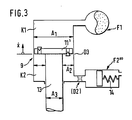
- FIG 3 shows an embodiment in which the springs F 1 and F 2 "'are opposite one another (as if mechanically connected in parallel).
- the spring F 1 is connected to the chamber K 1 and the spring F 2"' to the chamber K 2 a two-chamber piston displacer.
- the suspension shown in Fig. 3 has a dependency of the damping force on the frequency, with a dependency on the load.
- the suspension is fully load-bearing, which is why the cross section of the piston rod 13 is selected to be relatively large.
- the hydropneumatic spring F 1 is connected to the piston rod-free side of the piston displacer 9.
- a piston accumulator with a purely mechanical spring 14 is connected to the chamber K 2, that is to say the piston rod side of the displacer 9.
- the spring F 2 "'has a purely linear identifier, since the chamber in which the spring 14 is arranged is vented to the atmosphere.
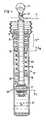
- FIG. 4 shows a somewhat more practical possibility of realizing the suspension principle shown more schematically in FIG. 3.
- the mechanical spring 14 is integrated in the piston displacer 9 'and is supported on the one hand on its cylinder cover 15 and on the other hand on a separating piston 16 delimiting the piston rod-side working space.
- This working space corresponds to the chamber K 2 as shown in FIG. 3.
- Below the piston 11 ' is the chamber K 1, which ver ver via the hollow piston rod 13' with the hydropneumatic spring F 1 is bound, the additional chokes D 1 are connected upstream.
- the connection 17 for level regulation is also indicated.
- tension stop spring 18 is provided, which can also be designed progressively.
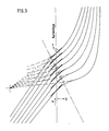
- FIG. 5 shows a family of characteristic curves as is possible with the suspension and damping according to FIG. 4 in conjunction with level regulation.
- a spring made of polyurethane or a similar rubber-elastic material supported on the stop ring 19 could also be used.
- the damping force profile is also influenced by the tension stop spring 18 as a function of the load.
- the damping force of the throttle D3 drops to zero, since the piston 11 'and the separating piston 16 move at the same speed.
- the sufficient basic damping then causes the throttle D1 (Fig. 4). It is also possible to completely omit the tension stop spring 18, the stop ring 19 (with a corresponding kink in the overall spring characteristic) striking against the separating piston 16 from a certain displacement path x and then taking it along.
- the additional load-dependent damping effect (load-dependent change in the displacer speed x) is superimposed on the effect of the system according to FIG. 3 (load-dependent increase in the displacer area from A 2 to A 1 ), the load dependency of the damping force is thus further increased.
- the tension stop spring 18 causes the action of the spring F 2"'(both act on the separating piston 16) the hydraulic system is corrected as if F 2 "'had a load-dependent (degressive) characteristic curve and was very hard in the empty state, but normal in the event of a load.
- the vehicle is empty while in the state of greater stress applies: respectively
- the different volume flow allocation to the at least two springs of the overall suspension system can therefore be achieved not only by different spring rate profiles - for example one with a progressive spring and the other with a linear identifier - but also by different switching of the springs, for example by parallel connection in the idle state and series connection under load.
- a spring F 1 or F 1 ′ of a wheel or wheel pair of a vehicle axle can also be connected to a second spring F 2 common to these two.
- the common spring F 2 is a piston accumulator, which is in the gas space by a Spring 5 was reinforced and thus linearized.
- the additional load-dependent structural damping can be provided by a throttle D 2 'provided at the input of the common spring F 2.
- a throttle D 4 it is also possible to install a throttle D 4 in each individual line 20 leading from the displacers 1 to the common second spring F 2.
- the additional body damping only comes into effect when the wheels move in the same direction, while when the wheels move in opposite directions, the oil is pushed unthrottled from one side to the other.
- this common spring F 12 can also be a diaphragm accumulator.
- the membrane 21 can rest on the feed opening 22 of the membrane accumulator at low working pressures.
- the spring F 12 only comes into operation when its filling pressure is exceeded by the system pressure. This embodiment therefore has the disadvantage that the spring and damping force curve change discontinuously.
- the piston 23 is supported by two mechanical springs 24 on the bottoms of the unit.
- the fluid chambers formed on both sides of the piston 23 are each assigned to a displacer 1 of one of the two wheels of an axle in an analogous manner to the exemplary embodiment according to FIG. 6.
- the variant according to FIG. 6 b does not allow any additional stroke damping, but only additional roll damping in connection with a roll spring rate that is softer than the stroke spring rate, since the piston 23 is only moved out of its central position against the force of the springs 24 when the wheels move against each other.
Description
Die Erfindung bezieht sich auf ein Federungssystem für Fahrzeuge, mit einem durch die Relativbewegungen zwischen Rad und Fahrzeugaufbau betätigbaren Verdränger, dessen Arbeitsraum unter Zwischenschaltung wenigstens einer Drossel mit mindestens zwei durch ein Strömungsmittel beaufschlagbaren Federn in Verbindung steht.The invention relates to a suspension system for vehicles, with a displacer which can be actuated by the relative movements between the wheel and the vehicle body and whose working space is connected to at least two springs which can be acted upon by a fluid with the interposition of at least one throttle.
Bekannte derartige Federungen (DE-B-14 30 836 oder DE-A-16 55 029) weisen jeweils zwei mit einem Verdränger verbundene hydropneumatische Federn auf. Mit diesen Systemen ist das Problem einer mit der Beladung des Fahrzeugs möglichst zunehmenden Aufbaudämpfung noch nicht befriedigend gelöst, wenn dabei gleichzeitig die Raddämpfung möglichst gleich bleiben soll.Known suspensions of this type (DE-B-14 30 836 or DE-A-16 55 029) each have two hydropneumatic springs connected to a displacer. With these systems, the problem of body damping that increases as much as possible with the loading of the vehicle has not yet been satisfactorily solved if the wheel damping is to remain as constant as possible.
Bei Federungssystemen der bereits genannten Art mit beispielsweise zwei hydropneumatischen Federn pro Fahrzeugrad ist wegen der annäherungsweise gültigen Formel p · v=const. jeder statischen Druckänderung LlPstat in jeder Feder eine anteilig gleiche relative Volumenänderung zugeordnet. Das bedeutet aber, daß das Verhältnis der vom Verdränger zu den zwei Federn verdrängten Teil-Volumenströme immer gleich ist:![]()
![]()


![]()
![]()
Mit Federungs- und Dämpfungssystemen für Kraftfahrzeuge der eingangs genannten Art besteht bisher, ebenso wie bei Verwendung einer mechanischen Federung zusammen mit herkömmlichen Stoßdämpfern, die Notwendigkeit, in der Bedämpfung der Federung Kompromisse zu schließen. Ist die Dämpfung auf eine mittlere Beladung des Fahrzeugs abgestimmt, so wird sie bei geringer Beladung als zu hart und bei großer Zuladung als zu weich empfunden werden.With suspension and damping systems for motor vehicles of the type mentioned at the outset, as well as when using mechanical suspension together with conventional shock absorbers, there has been a need to make compromises in the damping of the suspension. If the damping is matched to a medium load of the vehicle, it will be perceived as too hard for a low load and too soft for a large load.
Legt man bei der Festlegung der Dämpferkennung auch noch ein verstärktes Gewicht auf die bei etwa 12 Hz liegende Radeigenfrequenz, so besteht die Gefahr, daß im Bereich der Aufbaueigenfrequenz von etwa 1,2 Hz überhaupt keine ausreichende Dämpfung mehr vorhanden ist. Dies führt zum Beispiel dazu, daß neben speziellen Komfortabstimmungen auch noch Sportabstimmungen angeboten werden.If one also places an increased weight on the natural wheel frequency at approximately 12 Hz when determining the damper detection, there is a risk that in the area of the natural body frequency of approximately 1.2 Hz there will be no sufficient damping at all. This leads, for example, to the fact that in addition to special comfort settings, sport settings are also offered.
Es sind schon viele Versuche unternommen worden, die Dämpfung etwa lastabhängig, oder wegabhängig, oder auch frequenzabhängig zu verändern.Many attempts have already been made to change the damping, for example, depending on the load or path, or also frequency-dependent.
Bei wegabhängigen Dämpfungsänderungen kann über einen Stellkolben zum Beispiel eine größere Anzahl von Drossel-öffnungen freigegeben oder überdeckt werden. Durch die DE-A-26 55 705 ist eine Möglichkeit aufgezeigt worden, ab einem bestimmten Ausfeder- oder Einfederweg zusätzliche Hilfsdämpfungskolben wirksam werden zu lassen. Bei Austin-Fahrzeugen ist eine wegabhängige Änderung der Verdrängerfläche vorgesehen, während weiterhin auch schon eine Änderung der Verdrängergeschwindigkeit durch Änderung des Übersetzungsverhältnisses zwischen Radhub und Dämpferhub vorgeschlagen wurde. Den wegabhängigen Dämpfungen haftet der Nachteil an, daß bei niveaugeregelten Fahrzeugen die Dämpfkraft nicht mit der Belastung ansteigt, da der Fahrzeughöhenstand konstant bleibt.In the case of path-dependent damping changes, a larger number of throttle openings can be released or covered, for example, by means of an actuating piston. DE-A-26 55 705 has shown a possibility of allowing additional auxiliary damping pistons to take effect from a certain rebound or compression travel. In Austin vehicles, a displacement-dependent change in the displacement area is provided, while a change in the displacement speed by changing the gear ratio between wheel stroke and damper stroke has also been proposed. The path-dependent damping has the disadvantage that in level-controlled vehicles the damping force does not increase with the load, since the vehicle height remains constant.
Die Dämpfung bei hypdropneumatischen Federunge in Abhängigkeit vom Gasfederdruck zu verändern, ist ebenfalls bereits bekannt (DE-A-15 55 382 oder 15 55 383), doch benötigen diese Lösungen durchwegs aufwendige und wegen der Verschmutzungsgefahr und des Verschleißes störanfällige Steuereinrichtungen, wobei zum Vermeiden von unkontrollierten Schaltstößen das Stellglied seinerseits wiederum bedämpft werden muß, was dann wieder zu einer vergrößerten Temperaturabhängigkeit führt.The damping in hypropneumatic suspension depending on the gas spring pressure is also already known (DE-A-15 55 382 or 15 55 383), but these solutions require elaborate control devices which are susceptible to contamination and wear and tear, thereby avoiding uncontrolled switching impacts the actuator in turn must be damped, which then leads to an increased temperature dependence.
Schließlich sind auch schon frequenzabhängige Änderungen der Drosselquerschnitte vorgeschlagen worden, wie etwa aus der DE-B-10 45 256 oder der DE-A-15 55 491 hervorgeht. Die dabei verwendeten frequenzempfindlichen Trägheitsmassen bewirken noch ' verstärkt den bereits angedeuteten Nachteil einer großen Temperaturabhängigkeit, da wegen der schnellen Druckstöße eine besonders hohe Eigendämpfung der Stellglieder erforderlich ist.Finally, frequency-dependent changes in the throttle cross sections have also been proposed, as can be seen, for example, from DE-B-10 45 256 or DE-A-15 55 491. The frequency-sensitive inertial masses used in this case 'further increase the already indicated disadvantage of a large temperature dependency, since particularly high internal damping of the actuators is required because of the rapid pressure surges.
Es ist ferner noch aus der DE-C-16 75 634 oder DE-A-24 06 835 ein Luftfeder- und Dämpfer-System bekannt, das last- und frequenzabhängig arbeitet, doch sind dabei vergleichsweise sehr hohe Luftmengen erforderlich, um überhaupte eine ausreichende Dämpfungsarbeit erzielen zu können. Schon bei relativ geringen Verdrängergeschwindigkeiten fallen die Dämpferkräfte beträchtlich ab und die Gesamtfederrate wird deutlich erhöht, was einen schnellen Anstieg der Aufbaufrequenz zur Folge hat.It is also known from DE-C-16 75 634 or DE-A-24 06 835 an air spring and damper system that works depending on the load and frequency, but comparatively very large amounts of air are required to ensure sufficient at all To be able to achieve damping work. Even at relatively low displacement speeds, the damper forces drop considerably and the total spring rate is significantly increased, which results in a rapid increase in the assembly frequency.
Durch die DE-A-20 17 098 ist ein hydropneumatisches Federungssystem mit automatischer Leckflüssigkeitsnachregelung bekannt, bei dem der Ölraum des Verdrängers mit zwei Gasräumen-dem eigentlichen Gasfederraum und dem Verstellgasraum eines Verstellgliedes-in Verbindung steht. Dem Verstellglied ist dabei auch eine Drossel vorgeschaltet (Fig. 5), doch ist sie der progressiveren Feder der beiden Federn vorgeschaltet, wenn man (theoretisch) unterstellt, daß das Verstellglied überhaupt wesentlich Federarbeit übernimmt, was nach der Beschreibung jedoch nicht der Fall ist. Die erwähnte Drossel würde jedoch bei zunehmender Belastung des Systems immer weniger wirksam, was unerwünscht ist.From DE-A-20 17 098 a hydropneumatic suspension system with automatic leak fluid readjustment is known, in which the oil chamber of the displacer with two gas chambers - the actual gas spring chamber and the adjusting gas chamber of an adjuster member-related. A throttle is also connected upstream of the adjusting element (FIG. 5), but it is connected upstream of the more progressive spring of the two springs if (theoretically) it is assumed that the adjusting element takes on essentially spring work, which, however, is not the case according to the description. The throttle mentioned would, however, become less and less effective with increasing load on the system, which is undesirable.
Der Erfindung liegt die Aufgabe zugrunde, ein Federungssystem für Fahrzeuge der eingangs genannten Art zu schaffen, mit dem auf besonders einfache Weise bei zunehmender Belastung des Systems auch die Dämpfung ansteigt. Dabei soll auch die Möglichkeit eröffnet werden, durch weitere Ausgestaltungen die Dämpfung frequenzabhängig zu verändern.The invention has for its object to provide a suspension system for vehicles of the type mentioned, with which the damping increases in a particularly simple manner with increasing load on the system. The possibility is also to be opened here of changing the damping as a function of frequency by means of further configurations.
Diese Aufgabe wird bei einer Federung der vorausgesetzten Gattung dadurch gelöst, daß die Federn unterschiedliche belastungsabhängige Federratenänderungen haben, wodurch jeweils abhängig vom stätischen Strömungsmitteldruck eine unterschiedliche Aufteilung der zu den Federn verdrängten Volumenanteile erfolgt, und daß ferner zumindest eine lastabhängig wirksame Drossel der weniger progressiven Feder vorgeschaltet ist.This object is achieved in a suspension of the presupposed type in that the springs have different load-dependent changes in the spring rate, which means that depending on the static fluid pressure there is a different distribution of the volume portions displaced to the springs, and that at least one load-dependent throttle is connected upstream of the less progressive spring is.
So kann zum Beispiel bei niedriger Belastung, also niedrigem Strömungsmitteldruck, die erste Feder vergleichsweise weicher sein als die zweite, weshalb bei dieser Belastung der Anteil des zu dieser weicheren Feder vordrängten Strömungsmittels größer ist als der Anteil des zu der zweiten Feder verdrängten Strömungsmittels. Die der zweiten Feder vorgeschaltete Drossel wird daher-wegen des verminderten durch sie strömenden Volumenanteils-nur weniger Dämpfkraft erzeugen. Hat die genannte erste Feder (zum Beispiel eine hydropneumatische Feder mit konstanter Gasmasse) bei höherer Belastung schon eine wesentlich höhere Federrate als etwa die erwähnte zweite Feder, so strömt bei dieser Beladung zu den nun "weicheren" zweiten Feder ein wesentlich höherer Anteil des verdrängten Volumens, weshalb dann die der zweiten Feder vorgeschaltete Drossel bedeutend mehr Dämpfkraft erzeugt. Die Drossel übt daher bei höherer Beladung des Fahrzeugs in der mit der Erfindung angestrebten Weise eine höhere Dämpfkraft aus als bei bei geringer Beladung, wobei die Dämpfkraftübergänge stufenlos erfolgen.For example, at low loads, that is to say low fluid pressure, the first spring can be comparatively softer than the second, which is why, at this load, the proportion of the fluid pushed into this softer spring is greater than the proportion of the fluid displaced towards the second spring. The throttle upstream of the second spring will therefore only produce less damping force because of the reduced volume fraction flowing through it. If the first spring mentioned (for example a hydropneumatic spring with a constant gas mass) already has a significantly higher spring rate than the second spring mentioned under higher loads, then a much higher proportion of the displaced volume flows to the now "softer" second spring during this loading , which is why the throttle upstream of the second spring generates significantly more damping force. The throttle therefore exerts a higher damping force when the vehicle is heavily loaded than in the case of a low load, the damping force transitions being infinitely variable.
Der vorstehend umschriebene Grundgedanke ist in einer größeren Anzahl von Ausgestaltungen und besonders vorteilhaften Weiterbildungen realisierbar, die Gegenstand von Unteranprüchen sind, und im folgenden anhand der Zeichnung näher erläutert werden. Es zeigen:
- Fig. 1 eine Schemadarstellung einer ersten Ausführungsform der neuen Federung;
- Fig. 1a und b typisch Federkennlinien der in Fig. 1 dargestellten beiden Federn;
- Fig. 2 ein weiteres Ausführungsbeispiel der neuen Federung;
- Fig. 2 a und b Federkennlinien zu den in Fig. 2 dargestellten Federn;
- Fig. 3 eine weitere Ausführungsform der erfindungsgemäßen Federung;
- Fig. 4 eine technische Ausgestaltung des in Fig. 3 dargestellten Prinzips;
- Fig. 5 Kennlinien der Federung nach Fig. 4 bei Verwendung dieser Federung mit einer Niveauregulierung;
- Fig. 6 eine Ausführungsform der neuen Federung für die Räder oder Radpaare einer Fahrzeugachse und
- Fig. 6 a und b weitere Ausgestaltungen zu der in Fig. 6 schematisch dargestellten Federung.
- Figure 1 is a schematic representation of a first embodiment of the new suspension.
- Fig. 1a and b typical spring characteristics of the two springs shown in Fig. 1;
- Fig. 2 shows another embodiment of the new suspension;
- 2 a and b spring characteristic curves for the springs shown in FIG. 2;
- 3 shows a further embodiment of the suspension according to the invention;
- FIG. 4 shows a technical embodiment of the principle shown in FIG. 3;
- Fig. 5 characteristics of the suspension of Figure 4 when using this suspension with a level control.
- Fig. 6 shows an embodiment of the new suspension for the wheels or pairs of wheels of a vehicle axle and
- 6 a and b further refinements to the suspension shown schematically in FIG. 6.
Mit der in Fig. 1 dargestellten Federung ist eine vornehmlich lastabhängig veränderliche Dämpfung erreichbar. Die Federung umfaßt einen Verdränger 1 in Dämpferbauart, bei dem die Kolbenstange 2 als der eigentliche Verdränger dient. Im Kolben 3 ist die Drossel D 3 für die Grunddämpfung vorgesehen. Die Drossel D 3 kann aus federbelasteten Ventilen für die Raddämpfung in Verbindung mit einer Konstant- öffnung bestehen, die so groß bemessen ist, daß eine ausreichende Aufbaudämpfung bei leerem Fahrzeug sichergestellt ist.With the suspension shown in FIG. 1, damping that is primarily variable as a function of the load can be achieved. The suspension comprises a damper type displacer 1, in which the piston rod 2 serves as the actual displacer. In the
Die Federn F1 und F2 sind räumlich nebeneinander angeordnet, und in der Federwirkung in Serie geschaltet;The springs F1 and F2 are arranged spatially next to one another and connected in series in the spring action;
das heißt, daß das von der Kolbenstange 2 beim Einfedern verdrängte Ölvolumen in zwei Volumenströme aufgeteilt wird, von denen der eine der Feder F 1 und der andere der Feder F 2 zugeleitet wird. Bei dem dargestellten Ausführungsbeispiel ist der Feder F 2 eine Drossel D 2 vorgeschaltet, die die zusätzliche Aufbaudämpfung bei höherer Last übernimmt. Die beiden Federn F 1 und F 2 sind hydropneumatische Federn, wobei die Feder F 1 ein Membranspeicher und die Feder F 2 ein Kolbenspeicher ist. Beide Federn haben konstante Gasmassen. Der Kolben 4 der Feder F 2 ist mit einer mechanischen Zusatz-Feder 5 verbunden, die als Druckfeder im Gasraum des Kolbenspeichers angeordnet ist. Mit der Zusatz-Feder 5 wird die Kennlinie der Feder F 2 "linearisiert", wie ein Vergleich der Fig. 1 a und 1 b zeigen soll.this means that the oil volume displaced by the piston rod 2 during compression is divided into two volume flows, one of which is fed to the spring F 1 and the other to the spring F 2. In the illustrated embodiment, the spring F 2 is preceded by a throttle D 2, which takes over the additional body damping at higher loads. The two springs F 1 and F 2 are hydropneumatic springs, the spring F 1 being a diaphragm accumulator and the spring F 2 being a piston accumulator. Both springs have constant gas masses. The piston 4 of the spring F 2 is connected to a mechanical
In Fig. 1 a ist der typische Kennlinienverlauf einer Gasfeder aufgetragen, die bei geringer Belastung (pstat. leer) noch einen vergleichsweise flachen Verlauf hat, der aber bei zunehmender Belastung (Pstat. bel.) schnell sehr steil wird.In Fig. 1 a the typical characteristic curve of a gas spring is plotted, which with a low load (p stat . Empty) still has a comparatively flat curve, but which quickly becomes very steep with increasing load ( Pstat . Bel .).
Der in Fig. 1 b dargestellte Kannlinienverlauf der Feder F 2 ist bei geringer Beladung steiler als der entsprechende Verlauf der Feder F 1 (Fig. 1 a), wegen der "Linearisierung" ist er jedoch bei hoher Belastung im Vergleich zur Feder F 1 flacher. Bei geringem statischen Druck Pstat. leer wird daher die Feder F 1 im Vergleich zur Feder F 2 den größeren Anteil des von der Kolbenstange verdrängten Volumenstroms aufnehmen (V 1>V 2). Mit zunehmendem statischen Druck wächst der Anteil V 2 an, da die Feder F 2 die weniger progressive Feder ist. Damit strömt auch durch die Drossel D 2 mehr Ö1, wodurch eine kontinuierlich mit der Last zunehmende Aufbaudämpfung erreichbar ist. Bei höheren Verdrängergeschwindigkeiten wird dieser lastabhängige Dämpfungseffekt noch vom Durchflußwiderstand der Drossel D 2 und vom Trägheitswiderstand des Kolbens 4 der Feder F 2 verstärkt.The bend line curve of the spring F 2 shown in FIG. 1 b is steeper when the load is low than the corresponding curve of the spring F 1 (FIG. 1 a), but because of the “linearization” it is flatter in comparison to the spring F 1 at high load . At low static pressure Ps did. Empty spring F 1 will therefore take up the greater part of the volume flow displaced by the piston rod compared to spring F 2 (V 1> V 2). With increasing static pressure, the proportion V 2 increases, since the spring F 2 has less progressive spring is. This means that more Ö1 flows through throttle D 2, which means that body damping that increases continuously with the load can be achieved. At higher displacement speeds, this load-dependent damping effect is reinforced by the flow resistance of the throttle D 2 and the inertia resistance of the piston 4 of the spring F 2.
Bei der im Bild 2 schematisch dargestellten Ausführungsform einer Federung ist der Verdränger ein reiner Plunger-Kolben 6. Die Grunddämpfung übernehmen die den Federn F 1 und F 2' vorgeschalteten Drosseln D 1 und D 2. Von diesen beiden Drosseln hat die Drossel D 2 den größeren Durchflußwiderstand und bestimmt die zusätzliche Aufbaudämpfung:In the embodiment of a suspension shown schematically in Figure 2, the displacer is a
Die für die Verwirklichung des Erfindungsgedankens unterschiedlichen Kennlinien der Federn F 1 und F 2' werden bei dieser Ausführungsform dadurch verwirklicht, daß die Feder F 1 als Feder mit konstantem Gasgewicht und die Feder F 2' als Feder mit variablem Gasgewicht ausgebildet ist. Zweckmäßig ist der Gasraum der Feder F 2' an eine Niveau-Regulierung angeschlossen, wie dies in Bild 2 durch die Leitung 7 angedeutet ist.The different characteristics of the springs F 1 and F 2 'for realizing the inventive concept are realized in this embodiment in that the spring F 1 is designed as a spring with a constant gas weight and the spring F 2' as a spring with a variable gas weight. The gas space of the spring F 2 'is expediently connected to a level regulator, as is indicated in FIG. 2 by the
In Fig. 2 a ist der Kennlinienverlauf der Feder F 1 dargestellt während in Fig. 2 b die untere Kurve der Verlauf der Feder F 2' wäre, wenn sie nicht niveaugeregelt wäre. Die obere Kurve gibt die Kennlinie der Feder F 2' bei höherer Belastung an.2 a shows the characteristic curve of the spring F 1, while in FIG. 2 b the lower curve would be the curve of the spring F 2 'if it were not level-controlled. The upper curve shows the characteristic of the spring F 2 'at higher loads.
Aus den Fig. 2 a und 2 b geht hervor, daß die Feder F 1 mit zunehmender Belastung härter wird, während die Feder F 2' jedoch weicher wird. Die Niveau-Regulierung führt nämlich der Feder F 2' die Gasmenge zu, die durch die Kompression beider Federn F 1 und F 2' verschluckt wurde. Dadurch wird F 2' noch weicher als zum Beispiel eine einzelne Feder mit konstantem Gasvolumen (jedoch geregelter Gasmasse), der lediglich das von ihr selbst komprimierte Gasvolumen zugeführt wird.2a and 2b show that the spring F 1 becomes harder with increasing load, but the spring F 2 'becomes softer. The level regulation namely supplies the spring F 2 'with the amount of gas which has been swallowed by the compression of both springs F 1 and F 2'. This makes F 2 'even softer than, for example, a single spring with a constant gas volume (but regulated gas mass), to which only the gas volume compressed by itself is supplied.
Mit dem Ausführungsbeispiel nach Fig. 2 erhält man ebenfalls eine von der Belastung abhängige unterschiedliche Aufteilung der Volumenströme, wobei wegen der im Vergleich größeren Weichheit der Feder F 2' die Aufbaudämpfung über die Belastung noch schneller ansteigt als bei dem Ausführungsbeispiel nach Fig. 1, falls die übrigen Parameter konstant gehalten werden.With the embodiment according to FIG. 2 one also obtains a different division of the volume flows depending on the load, whereby due to the comparatively greater softness of the spring F 2 'the body damping increases even faster over the load than in the embodiment according to FIG. 1, if the other parameters are kept constant.
Fig. 3 zeigt eine Ausführungsform, bei der die Federn F 1 und F 2"' gegenüber einander stehen (wie mechanisch parallelgeschaltet). Die Feder F 1 ist dabei an die Kammer K 1 und die Feder F 2"' an die Kammer K 2 eines Zweikammer-Kolbenverdrängers angeschlossen.3 shows an embodiment in which the springs F 1 and F 2 "'are opposite one another (as if mechanically connected in parallel). The spring F 1 is connected to the chamber K 1 and the spring F 2"' to the chamber K 2 a two-chamber piston displacer.
Die in Fig. 3 dargestellte Federung hat eine Abhängigkeit der Dämpfkraft von der Frequenz, wobei noch eine Abhängigkeit von der Last dazukommt. Die Federung ist volltragend, weshalb der Querschnitt der Kolbenstange 13 relativ groß gewählt ist. Die hydropneumatische Feder F 1 ist an die kolbenstangenfreie Seite des Kolbenverdrängers 9 angeschlossen. Mit der Kammer K 2, also der Kolbenstangenseite des Verdrängers 9 ist ein Kolbenspeicher mit einer rein mechanischen Feder 14 verbunden. Die Feder F 2"' hat eine rein lineare Kennung, da die Kammer, in der die Feder 14 angeordnet ist, zur Atmosphäre entlüftet ist.The suspension shown in Fig. 3 has a dependency of the damping force on the frequency, with a dependency on the load. The suspension is fully load-bearing, which is why the cross section of the
Bei geringen Verdrängergeschwindigkeiten, etwa im Bereich der Aufbaueigenfrequenz, ist die Wirkungsweise weitgehend wie bei der Federung nach Fig. 1: bei einem niedrigen statischen Druck wird das von der Kolbenstange 13 verdrängte Ölvolumen hauptsächlich zu der (bei diesem Druck) weicheren Feder F 1 gefördert (V 1>V 2). Mit zunehmendem statischen Druck nimmt die Federrate von F 1 zu, während die Federrate von F 2"' konstant bleibt, wodurch sich der Anteil V 1 gegenüber V 2 zunehmend verringert. Der Dämpfkraftverlauf läßt sich mit Hilfe folgender Grenzfälle erläutern:
- V 1»V 2: Bei einer sehr weichen Feder F 1 wird praktisch kein Ö1 zur Feder F 2'" gefördert. Deshalb strömt durch
das Kolbenventil D 3 der gedrosselte Volumenstrom Vα 3 leer=A2x. Hierbei ist x die Verdrängergeschwindigkeit und A2 die Ringflänce zwischen Zylinder und Kolbenstange (=A1-A3). - V1«V2: Bei einem hohen statischen Druck kann die Feder F 1 kaum noch dynamisch einfedern, deshalb erhöht sich der gedrosselte Volumenstrom auf
V D 3 bel.=A1X. Die für das Dämpfungs-Volumen wirksame Verdrängerfläche hat sich also von der Ringfläche A2 auf die Zylinderfläche A1 vergrößert; damit steigt auch die Dämpfkraft im gleichen Verhältnis an. Falls erforderlich, kann die Dämpfkraftsteigerung noch durch eine der Feder F 2"' vorgeschaltete und somit bei höheren Drücken zunehmend wirksame Drossel D 2 verstärkt werden.
- V 1 »V 2: With a very soft spring F 1, practically no oil is conveyed to the spring F 2 '". Therefore, the throttled volume flow Vα 3 flows through the
piston valve D 3 = A 2 x. Here, x is the displacement speed and A 2 the ring flange between cylinder and piston rod (= A 1 -A 3 ). - V 1 «V 2 : At a high static pressure, the spring F 1 can hardly deflect dynamically anymore, which is why the throttled volume flow increases to
V D 3 bel . = A 1 X. The displacement area effective for the damping volume has therefore changed from the ring area A 2 enlarged to the cylinder area A 1 ; this also increases the damping force in the same ratio. If necessary, the increase in damping force can be increased by a throttle D 2 connected upstream of the spring F 2 ″ and thus increasingly effective at higher pressures.
Bei höheren Verdrängergeschwindigkeiten, etwa im Bereich der Radfrequenzen, werden der statischen Druckerhöhung noch die dynamischen Druckunterschiede (infolge des größeren Druckabfalls an der Drossel D 3) überlagert. Das wirkt sich dahingehend aus, daß der Durchsatz durch die Drossel D 3 abnimmit und dafür die Federn F 1 und F 2"' stärker aktiviert werden. Im Grenfall (Durchfluβwiderstand→∞) arbeitet der Kolben 11 als einer Verdränger, der das gesamte Zylindervolumen zwischen den nun parallel geschalteten Federn F 1 und F 2"' hin- und herschiebt.At higher displacement speeds, for example in the range of the wheel frequencies, the static pressure increase is still superimposed on the dynamic pressure differences (due to the greater pressure drop at the throttle D 3). This has the effect that the throughput through the
Fig. 4 zeigt eine etwas praxisnähere Realisierungsmöglichkeit des in Fig. 3 mehr schematisch dargestellten Federungsprinzips. Die mechanische Feder 14 ist dabei in den Kolbenverdränger 9' integriert und stützt sich einerseits an dessen Zylinderdeckel 15 und andererseits an einem den kolbenstangenseitigen Arbeitsraum begrenzenden Trennkolben 16 ab. Dieser Arbeitsraum entspricht der Kammer K 2 der Darstellung nach Fig. 3. Unterhalb des Kolbens 11' befindet sich die Kammer K 1, die über die hohle Kolbenstange 13' mit der hydropneumatischen Feder F 1 verbunden ist, der zusätzliche Drosseln D 1 vorgeschaltet sind. Vor der Drossel D 1 ist noch der Anschluß 17 für eine Niveau-Regulierung angedeutet.FIG. 4 shows a somewhat more practical possibility of realizing the suspension principle shown more schematically in FIG. 3. The
Zwischen dem Trennkolben 16 und dem Kolben 11' ist eine Zuganschlagfeder 18 vorgesehen, die auch progressiv ausgebildet sein kann.Between the
Die Integration der Feder 14 in der beschriebenen Weise in den Verdränger 9' bietet im Vergleich zu der Prinzipdarstellung nach Fig. 3 den Vorteil, daß zusätzlich zur hydraulischen Beaufschlagung der Feder F 2'" diese auch direkt durch den Kolben 11' oder die Kolbenstange 13' betätigt werden kann, so daß sich weitere Variationsmöglichkeiten sowohl in der Wahl des Dämpfkraftals auch des Federkraftverlaufs ergeben. Die bei dem dargestellten Ausführungsbeispiel über den Anschlagring 19 betätigte Zuganschlagfeder 18 hat einen lastabhängigen Einstazpunkt, da sie sich an dem lastabhängig verschieblichen Trennkoolben 16 abstützt.The integration of the
In Fig. 5 ist eine Kennlinienschar dargestellt, wie sie mit der Federung und Dämpfung nach Fig. 4 in Verbindung mit einer Niveau-Regulierung möglich ist.FIG. 5 shows a family of characteristic curves as is possible with the suspension and damping according to FIG. 4 in conjunction with level regulation.
Je schwerer das Fahrzeug beladen ist (obere Kurven der Kurvenschar), je weiter also die Feder 14 und damit auch der Trennkolben 16 einfedert, desto später setzt auch die Zuganschlagfeder 18 ein, wie aus Fig. 5 hervorgeht.The heavier the vehicle is loaded (upper curves of the family of curves), the further the
Man erkennt dabei ferner, daß die Federkennlinien um die Normallage alle die gleiche Steigung (Tangente T) haben. Durch den lastabhängigen Einsatzpunkt der Zuganschlagfeder 18 wird also die Progressivität der hydropneumatischen Feder F 1 wieder kompensiert.It can also be seen that the spring characteristics around the normal position all have the same slope (tangent T). The progressive nature of the hydropneumatic spring F 1 is thus compensated for again by the load-dependent point of use of the
Je nach Auslegung der Stahl-Feder 14, die den Verlauf des Zuganschlagfeder-Einsatzes und damit die Lage der strichpunktierten Geraden bestimmt, läßt sich zum Beispiel auch ein konstanter Eigenfrequenzverlauf über der Beladung erreichen, was sonst nur durch parallel geschaltete Stahlund Gasfedern zu erzielen ist.Depending on the design of the
Anstelle der in dem Ausführungsbeispiel nach Fig. 4 dargestellten, ggf. progressiven, Zuganschlagfeder 18 könnte auch eine sich auf dem Anschlagring 19 abstützende Feder aus polyurethan oder einem änhlichen gummielastischen Material Verwendung finden.Instead of the possibly progressive
Neben dem Federratenverlauf wird durch die Zuganschlagfeder 18 auch der Dämpfkraftverlauf lastabhängig beeinflußt. Sobald nämlich die Zuganschlagfeder 18 einsetzt, verändert sie die Geschwindigkeit X16 des Trennkolbens 16 und damit auch die Dämpfkraft der Drossel D3 des Kolbens 11', da diese von der Differenzgeschwindigkeit zwischen dem Kolben 11' und Trennkolben 16 abhängt (VD3=A2 (x―x16)). Im Extremfall-Zuganschlagfeder 18 auf Block-fällt die Dämpfkraft der Drossel D3 auf Null ab, da der Koblen 11' und der Trennkolben 16 sich mit derselben Geschwindigkeit bewegen. Die ausreichende Grunddämpfung bewirkt dann die Drossel D1 (Fig. 4). Es ist auch möglich, die Zuganschlagfeder 18 ganz entfallen zu lassen, wobei der Anschlagring 19 (mit einem entsprechenden Knick in der Gesamt-Feder-Kennlinie) ab einem bestimmten Verdrängerweg x gegen den Trennkolben 16 anschlägt und diesen dann mitnimmt.In addition to the spring rate profile, the damping force profile is also influenced by the
Der zusätzlich lastabhängige Dämpfeffekt (lastabhängige Änderung der Verdrängergeschwindigkeit x) wird dem Effekt des Systems nach Fig. 3 (lastabahängige Erhöhung der Verdrängerfläche von A2 auf A1) überlagert, die Lastabhängigkeit der Dämpfkraft also noch verstärkt.The additional load-dependent damping effect (load-dependent change in the displacer speed x) is superimposed on the effect of the system according to FIG. 3 (load-dependent increase in the displacer area from A 2 to A 1 ), the load dependency of the damping force is thus further increased.
Deshalb ist auch eine lastabhängige Dämpfung denkbar, die nur auf diesem Effekt beruht; also ohne den anhand der Fig. 3 erläuterten Effekt, der unterschiedliche Federratenverläufe
![]()
![]()

![]()
![]()
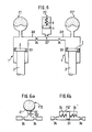
Wie man der wieder merh schematischen Darstellung einer Weiterbildung der Erfindung in Fig. 6 entnehmen kann, kann jeweils einer Feder F 1 bzw. F 1' eines Rades oder Radpaares einer Fahrzeugachse auch eine diesen beiden gemeinsame zweite Feder F 2 zugeschaltet sein. Wie bei dem Ausführungsbeispiel nach Fig. 1 handelt es sich bei der gemeinsamen Feder F 2 um einen Kolbenspeicher, der im Gasraum durch eine Feder 5 verstärkt und damit linearisiert wurde. Die zusätzliche, lastabhängige Aufbaudämpfung kann durch eine am Eingang der gemeinsamen Feder F 2 vorgesehene Drossel D 2' vorgesehen werden. Es ist aber auch möglich, in jede einzelne von den Verdrängern 1 zu der gemeinsamen zweiten Feder F 2 führend Leitung 20 jeweils eine Drossel D 4 einzubauen. Im ersten Fall tritt die zusätzliche Aufbaudämpfung nur bei gleichseitigen Radbewegungen in Kraft, während bei gegenseitiger Radbewegung das Ö1 ungedrosselt von einer Seite zur anderen geschoben wird. Im zweiten Fall ist eine zusätzliche Aufbaudämpfung bei gleich-und gegenseitigen Radbewegungen vorhanden, was neben der zusätzlichen Hubdämpfung auch eine zusätzliche Wankdämpfung ermöglicht.As can be seen from the schematic representation of a further development of the invention in FIG. 6, a spring F 1 or F 1 ′ of a wheel or wheel pair of a vehicle axle can also be connected to a second spring F 2 common to these two. As in the embodiment according to FIG. 1, the common spring F 2 is a piston accumulator, which is in the gas space by a
Anstelle des in Fig. 6 dargestellten Kolbenspeichers für die beiden Rädern gemeinsame zweite Feder F 2 kann diese gemeinsame Feder F 12 gemäß Fig. 6a auch ein Membranspeicher sein. Dabei kann die Membran 21 bei niedrigen Arbeitsdrücken auf der Zuleitungsöffnung 22 des Membranspeichers aufliegen. Die Feder F 12 tritt erst dann in Funktion, wenn ihr Fülldruck vom Systemdruck überschritten wird. Diese Ausführungsform hat daher der Nachteil, daß sich Feder- und Dämpfkraftverlauf unstetig ändern.Instead of the piston accumulator shown in FIG. 6 for the two wheels, common second spring F 2, this common spring F 12 according to FIG. 6 a can also be a diaphragm accumulator. The
Nach Fig. 6 b kann die gemeinsame Feder F 12' auch eine Zylinder/Kolben-Einheit sein. Der Kolben 23 stützt sich dabei über zwei mechanische Feder 24 an den Böden der Einheit ab. Die beiderseits des Kolbens 23 gebildeten Strömungsmittelkammern sind in analoger Weise wie zum Ausführungsbeispiel nach Fig. 6 jeweils einem Verdränger 1 eines der beiden Räder einer Achse zugeordnet.6b, the common spring F 12 'can also be a cylinder / piston unit. The
Die Variante nach Fig. 6 b ermöglicht keine zusätzliche Hubdämpfung, sondern nur eine zusätzliche Wankdämpfung in Verbindung mit einer gegenüber der Hubfederrate weicheren Wankfederrate, da der Kolben 23 nur bei gegenseitigen Radbewegungen entgegen der Kraft der Federn 24 aus seiner Mittellage bewegt wird.The variant according to FIG. 6 b does not allow any additional stroke damping, but only additional roll damping in connection with a roll spring rate that is softer than the stroke spring rate, since the
Claims (24)
Applications Claiming Priority (2)
| Application Number | Priority Date | Filing Date | Title |
|---|---|---|---|
| DE3044287 | 1980-11-25 | ||
| DE3044287 | 1980-11-25 |
Publications (3)
| Publication Number | Publication Date |
|---|---|
| EP0052782A2 EP0052782A2 (en) | 1982-06-02 |
| EP0052782A3 EP0052782A3 (en) | 1982-11-24 |
| EP0052782B1 true EP0052782B1 (en) | 1986-05-28 |
Family
ID=6117483
Family Applications (1)
| Application Number | Title | Priority Date | Filing Date |
|---|---|---|---|
| EP81108957A Expired EP0052782B1 (en) | 1980-11-25 | 1981-10-27 | Suspension system for vehicles |
Country Status (3)
| Country | Link |
|---|---|
| US (1) | US4478431A (en) |
| EP (1) | EP0052782B1 (en) |
| DE (1) | DE3174727D1 (en) |
Families Citing this family (53)
| Publication number | Priority date | Publication date | Assignee | Title |
|---|---|---|---|---|
| DE3414257C2 (en) * | 1984-04-14 | 1993-12-02 | Bosch Gmbh Robert | Spring element with variable hardness for vehicles |
| DE3526156A1 (en) * | 1985-07-22 | 1987-01-29 | Kaspar Lochner | Load-dependent spring-damper unit |
| DE3537325A1 (en) * | 1985-10-19 | 1987-04-23 | Messerschmitt Boelkow Blohm | ACTIVE SUSPENSION ELEMENT, ESPECIALLY FOR RAIL-SPEED HIGH-SPEED VEHICLES |
| JPS63301115A (en) * | 1987-05-29 | 1988-12-08 | Nissan Motor Co Ltd | Hydraulic suspension |
| DE3724271A1 (en) * | 1987-07-22 | 1989-02-02 | Bosch Gmbh Robert | DAMPING DEVICE |
| US4798398A (en) * | 1987-08-12 | 1989-01-17 | Unit Rig & Equipment Co. | Dual rate equalizer suspension |
| DE3824611A1 (en) * | 1988-07-20 | 1990-01-25 | Bayerische Motoren Werke Ag | SPRING-DAMPER SYSTEM FOR VEHICLES |
| US5016911A (en) * | 1988-07-29 | 1991-05-21 | Mazda Motor Corporation | Automotive suspension system |
| JP2584318B2 (en) * | 1989-07-14 | 1997-02-26 | マツダ株式会社 | Vehicle suspension device |
| WO1991004877A1 (en) * | 1989-09-29 | 1991-04-18 | Towerhill Holdings Pty Ltd | Interconnected fluid suspension for vehicles |
| ES2060888T3 (en) * | 1989-10-28 | 1994-12-01 | Hemscheidt Fahrwerktech Gmbh | HYDRO-PNEUMATIC SUSPENSION SYSTEM. |
| EP0426995B1 (en) * | 1989-11-07 | 1993-12-01 | Mercedes-Benz Ag | Hydropneumatic spring system |
| US5080392A (en) * | 1990-04-26 | 1992-01-14 | Cb Auto Design Inc. | Suspension unit |
| GB9015337D0 (en) * | 1990-07-12 | 1990-08-29 | Rodney Linval | Spring device |
| US5154442A (en) * | 1990-11-19 | 1992-10-13 | Milliken Douglas L | Self-contained acceleration-responsive adaptive damper |
| DE4102787C2 (en) * | 1991-01-31 | 1998-07-30 | Daimler Benz Ag | Suspension system, in particular for motor vehicles |
| DE4226754A1 (en) * | 1991-09-21 | 1993-03-25 | Bosch Gmbh Robert | SUSPENSION SYSTEM FOR VEHICLES |
| DE4234217C2 (en) * | 1992-10-10 | 1996-07-11 | Hemscheidt Fahrwerktech Gmbh | Hydropneumatic suspension system |
| WO1994008808A1 (en) * | 1992-10-10 | 1994-04-28 | Hemscheidt Fahrwerktechnik Gmbh & Co. Kg | Hydropneumatic suspension system |
| SE505594C2 (en) * | 1992-10-15 | 1997-09-22 | Oehlins Racing Ab | Device for shock absorber arrangement |
| US5322321A (en) * | 1992-12-28 | 1994-06-21 | Ford Motor Company | Vehicle active suspension system |
| US5374077A (en) * | 1993-01-11 | 1994-12-20 | Paccar Inc. | Pneumatically damped vehicle suspension system |
| IT1271171B (en) * | 1993-04-08 | 1997-05-27 | Fichtel & Sachs Ag | SHOCK ABSORBER OPERATING SELECTIVELY IN THE FREQUENCY |
| DE19608617A1 (en) * | 1996-03-06 | 1997-09-11 | Linke Hofmann Busch | Procedure for improving driving comfort |
| US5957252A (en) * | 1996-08-02 | 1999-09-28 | Berthold; Brian D. | Hydraulic suspension unit |
| GB2347395B (en) * | 1999-03-04 | 2002-07-31 | Rover Group | Vehicle suspension dampers |
| AUPR249901A0 (en) * | 2001-01-10 | 2001-02-01 | Kinetic Pty Limited | Vehicle suspension roll control system |
| DE60219708T2 (en) * | 2001-02-09 | 2007-12-27 | Technology Investments Ltd. | Hydropneumatic suspension system |
| US6837344B2 (en) | 2001-02-12 | 2005-01-04 | Delphi Technologies, Inc. | Piston and rod assembly for air-actuated variable damping |
| US6450304B1 (en) | 2001-02-12 | 2002-09-17 | Delphi Technologies, Inc. | Piston and rod assembly for air-actuated variable damping |
| US20020121416A1 (en) * | 2001-02-19 | 2002-09-05 | Yohei Katayama | Hydraulic cylinder apparatus |
| EP1361965A1 (en) * | 2001-02-23 | 2003-11-19 | Ribi Design (US) | Vehicle having interconnected suspensions |
| DE10336781A1 (en) * | 2002-08-09 | 2004-02-26 | Kerler Jun., Johann | Pneumatic suspension and height-adjuster for vehicle, comprises double-acting cylinder connected to equalization vessel and pressure source |
| DE10259532A1 (en) * | 2002-12-19 | 2004-07-01 | Daimlerchrysler Ag | Support bearing of a vibration-damping element |
| JP4155066B2 (en) * | 2003-03-12 | 2008-09-24 | トヨタ自動車株式会社 | Vehicle suspension system |
| US20050173849A1 (en) * | 2004-02-10 | 2005-08-11 | Bart Vandewal | Electronically controlled frequency dependent damping |
| DE102004027885A1 (en) * | 2004-05-28 | 2005-12-22 | Dr.Ing.H.C. F. Porsche Ag | Spring-damper unit for a chassis of a motor vehicle |
| JP2006076469A (en) * | 2004-09-10 | 2006-03-23 | Toyota Motor Corp | Suspension device |
| CA2657851C (en) * | 2006-07-28 | 2013-12-24 | Marabese Design S.R.L. | System to control the trim of motorcycles with three or four wheels |
| DE102006045236A1 (en) * | 2006-09-26 | 2008-04-03 | Zf Friedrichshafen Ag | Noise-optimized vibration damper |
| FR2907049B1 (en) * | 2006-10-11 | 2009-01-30 | Peugeot Citroen Automobiles Sa | AMENDED SUSPENSION DEVICE OF A VEHICLE |
| EP2303672A4 (en) | 2008-06-27 | 2013-05-29 | Absolute Electronic Solutions Inc | Fifth wheel trailer with adjustable deck |
| EP2527171A1 (en) * | 2008-11-18 | 2012-11-28 | Hemscheidt Fahrwerktechnik GmbH & Co. KG | Damping system for vehicles |
| ITTO20090139A1 (en) | 2009-02-26 | 2010-08-27 | Cnh Italia Spa | AGRICULTURAL VEHICLE |
| US8807542B2 (en) * | 2009-06-05 | 2014-08-19 | Fox Factory, Inc. | Apparatus and methods for a vehicle shock absorber |
| DE102011084089A1 (en) * | 2011-10-06 | 2013-04-11 | Bayerische Motoren Werke Aktiengesellschaft | Vehicle suspension with a hydraulic vibration damper |
| ITMI20121683A1 (en) * | 2012-10-08 | 2014-04-09 | Gabriele Bellani | SUSPENSION FOR VEHICLE WITH WHEELS |
| US9670979B1 (en) | 2016-05-13 | 2017-06-06 | Liquidspring Technologies, Inc. | Resilient expandable pressure vessel |
| EP3450772B1 (en) | 2017-09-01 | 2024-02-14 | Enerpac Tool Group Corp. | Hybrid spring for a hydraulic cylinder |
| DE102017218905B4 (en) * | 2017-10-24 | 2023-11-30 | Bayerische Motoren Werke Aktiengesellschaft | Spring-damper system with variable spring rate |
| JP2020168898A (en) * | 2019-04-01 | 2020-10-15 | ヤマハ発動機株式会社 | Suspension system and vehicle |
| JP7285118B2 (en) | 2019-04-01 | 2023-06-01 | ヤマハ発動機株式会社 | Suspension system and vehicle |
| DE102019211502B4 (en) * | 2019-08-01 | 2022-03-17 | Audi Ag | Spring-damper device for a vehicle, in particular for a motor vehicle, and vehicle with at least one such spring-damper device |
Family Cites Families (24)
| Publication number | Priority date | Publication date | Assignee | Title |
|---|---|---|---|---|
| US2620182A (en) * | 1947-10-15 | 1952-12-02 | Marston | Fluid actuated suspension device for vehicles, aircraft, and the like |
| GB931300A (en) * | 1959-12-23 | 1963-07-17 | Wilhelm Ley | Improvements in hydropneumatic stabilizers and spring suspension devices for motor vehicles |
| US3077345A (en) * | 1960-03-29 | 1963-02-12 | Svenska Aeroplan Ab | Air-oil shock absorber especially adapted for ground vehicles |
| BE639152A (en) * | 1962-12-05 | |||
| US3168302A (en) * | 1962-12-26 | 1965-02-02 | Caterpillar Tractor Co | Vehicle suspension systems |
| FR1422968A (en) * | 1964-11-16 | 1966-01-03 | Citroen Sa Andre | Double flexible hydropneumatic suspension |
| US3304076A (en) * | 1964-12-31 | 1967-02-14 | Letourneau Westinghouse Compan | Suspension unit |
| GB1113801A (en) * | 1965-04-23 | 1968-05-15 | Moulton Development Ltd | Improvements in automotive vehicle wheel spring suspension systems |
| DE1580236A1 (en) * | 1965-07-10 | 1970-01-29 | Langen & Co | Hydro-pneumatic suspension for vehicles |
| US3499639A (en) * | 1966-04-27 | 1970-03-10 | Saviem | Hydropneumatic suspension systems of vehicles |
| DE1291641B (en) * | 1966-10-08 | 1969-03-27 | Rheinstahl Henschel Ag | Connection device for a hydropneumatic spring element with connection gas bubble, especially for vehicles |
| FR1503903A (en) * | 1966-10-18 | 1967-12-01 | Citroen Sa Andre | Hydraulic suspension with multiple accumulators |
| DE1555226B2 (en) * | 1967-02-28 | 1977-05-12 | Daimler-Benz Ag, 7000 Stuttgart | HYDROPNEUMATIC SUSPENSION FOR VEHICLES, IN PARTICULAR MOTOR VEHICLES |
| FR1525246A (en) * | 1967-03-29 | 1968-05-17 | Ind Dev Company Establishments | Hydropneumatic suspension at two different gas pressures |
| DE2017098A1 (en) * | 1970-04-10 | 1971-10-28 | Fichtel & Sachs Ag, 8720 Schweinfurt | High pressure gas suspension system, especially for motor vehicles, with automatic leakage fluid readjustment |
| DE2020292A1 (en) * | 1970-04-25 | 1971-11-18 | Bosch Gmbh Robert | Support system for motor vehicles |
| FR2152351B1 (en) * | 1971-09-06 | 1974-05-10 | Citroen Sa | |
| JPS5135971B2 (en) * | 1972-03-27 | 1976-10-06 | ||
| DE2736026C2 (en) * | 1976-08-19 | 1985-10-24 | Honda Giken Kogyo K.K., Tokio/Tokyo | Hydro-pneumatic suspension for vehicles |
| US4153237A (en) * | 1976-11-01 | 1979-05-08 | Supalla Steven A | Hydrapneumatic suspension unit and valving structure |
| DE2655705C3 (en) * | 1976-12-09 | 1980-06-12 | Boge Gmbh, 5208 Eitorf | Hydraulic telescopic vibration damper with hydraulic and elastic cable stop, in particular for motor vehicles |
| HU177630B (en) * | 1978-04-14 | 1981-11-28 | Girling Ltd | Hydropneumatic spring for vehicles |
| FR2436030A1 (en) * | 1978-09-12 | 1980-04-11 | Leduc & Fils Rene | Hydropneumatic suspension for vehicle - has multiple accumulators, all but one with pressure isolating valve acting at different pressures |
| DE2843436C3 (en) * | 1978-10-05 | 1981-11-05 | Boge Gmbh, 5208 Eitorf | Hydropneumatic suspension for motor vehicles with a loading platform and at least one loading unit that can be placed on it |
-
1981
- 1981-10-27 EP EP81108957A patent/EP0052782B1/en not_active Expired
- 1981-10-27 DE DE8181108957T patent/DE3174727D1/en not_active Expired
- 1981-11-24 US US06/324,668 patent/US4478431A/en not_active Expired - Fee Related
Also Published As
| Publication number | Publication date |
|---|---|
| US4478431A (en) | 1984-10-23 |
| EP0052782A3 (en) | 1982-11-24 |
| DE3174727D1 (en) | 1986-07-03 |
| EP0052782A2 (en) | 1982-06-02 |
Similar Documents
| Publication | Publication Date | Title |
|---|---|---|
| EP0052782B1 (en) | Suspension system for vehicles | |
| EP0300204B1 (en) | Damper | |
| EP0351537B1 (en) | Spring damper system for vehicles | |
| DE19807211B4 (en) | vibration | |
| EP0824412B1 (en) | Hydropneumatic suspension | |
| DE3904071C2 (en) | ||
| DE102004013881B4 (en) | Double-piston shock absorbers | |
| EP0389828B1 (en) | Hydropneumatic spring system | |
| EP0367949B1 (en) | Springing system for vehicles | |
| DE4014466A1 (en) | VEHICLE SUSPENSION | |
| DE2836662B1 (en) | Air springs, especially for motor vehicles | |
| WO1994008808A1 (en) | Hydropneumatic suspension system | |
| DE19703872A1 (en) | Hydraulic damper | |
| DE102010051872B4 (en) | Vibration damper assembly | |
| DE3526156C2 (en) | ||
| EP0565832B1 (en) | Hydraulic vehicle vibration damper | |
| EP3700764A1 (en) | Spring-absorber system with variable spring rate | |
| EP0529320B1 (en) | Hydropneumatic spring system for a vehicle's lift axle | |
| DE3907462A1 (en) | ROLL BELLOW AIR SPRING | |
| DE1655003B2 (en) | Brake pressure regulators for hydraulically actuated vehicle brake systems, in particular vehicle brake systems | |
| EP2977640A2 (en) | Vibration absorber | |
| EP1529173A1 (en) | Controllable piston valve and/or flap valve for a vibration damper | |
| DE3111410C2 (en) | Load-dependent controllable damping valve for vehicles | |
| EP1053116B1 (en) | Vehicle suspension system | |
| DE3935608A1 (en) | Piston cylinder unit as shock or vibration absorber - has cylinder and equaliser compartments with spring chamber |
Legal Events
| Date | Code | Title | Description |
|---|---|---|---|
| PUAI | Public reference made under article 153(3) epc to a published international application that has entered the european phase |
Free format text: ORIGINAL CODE: 0009012 |
|
| AK | Designated contracting states |
Designated state(s): DE FR GB IT SE |
|
| PUAL | Search report despatched |
Free format text: ORIGINAL CODE: 0009013 |
|
| KL | Correction list |
Free format text: 82/06 TITELBLATT |
|
| AK | Designated contracting states |
Designated state(s): DE FR GB IT SE |
|
| 17P | Request for examination filed |
Effective date: 19830422 |
|
| ITF | It: translation for a ep patent filed |
Owner name: STUDIO JAUMANN |
|
| GRAA | (expected) grant |
Free format text: ORIGINAL CODE: 0009210 |
|
| AK | Designated contracting states |
Kind code of ref document: B1 Designated state(s): DE FR GB IT SE |
|
| REF | Corresponds to: |
Ref document number: 3174727 Country of ref document: DE Date of ref document: 19860703 |
|
| ET | Fr: translation filed | ||
| PLBE | No opposition filed within time limit |
Free format text: ORIGINAL CODE: 0009261 |
|
| STAA | Information on the status of an ep patent application or granted ep patent |
Free format text: STATUS: NO OPPOSITION FILED WITHIN TIME LIMIT |
|
| 26N | No opposition filed | ||
| PGFP | Annual fee paid to national office [announced via postgrant information from national office to epo] |
Ref country code: DE Payment date: 19901002 Year of fee payment: 10 |
|
| PGFP | Annual fee paid to national office [announced via postgrant information from national office to epo] |
Ref country code: SE Payment date: 19901016 Year of fee payment: 10 |
|
| PGFP | Annual fee paid to national office [announced via postgrant information from national office to epo] |
Ref country code: GB Payment date: 19901025 Year of fee payment: 10 |
|
| PGFP | Annual fee paid to national office [announced via postgrant information from national office to epo] |
Ref country code: FR Payment date: 19901030 Year of fee payment: 10 |
|
| ITTA | It: last paid annual fee | ||
| PG25 | Lapsed in a contracting state [announced via postgrant information from national office to epo] |
Ref country code: GB Effective date: 19911027 |
|
| PG25 | Lapsed in a contracting state [announced via postgrant information from national office to epo] |
Ref country code: SE Effective date: 19911028 |
|
| GBPC | Gb: european patent ceased through non-payment of renewal fee | ||
| PG25 | Lapsed in a contracting state [announced via postgrant information from national office to epo] |
Ref country code: FR Effective date: 19920630 |
|
| PG25 | Lapsed in a contracting state [announced via postgrant information from national office to epo] |
Ref country code: DE Effective date: 19920701 |
|
| REG | Reference to a national code |
Ref country code: FR Ref legal event code: ST |
|
| EUG | Se: european patent has lapsed |
Ref document number: 81108957.2 Effective date: 19920510 |