EP0052709B1 - Distributing valve - Google Patents
Distributing valve Download PDFInfo
- Publication number
- EP0052709B1 EP0052709B1 EP81107400A EP81107400A EP0052709B1 EP 0052709 B1 EP0052709 B1 EP 0052709B1 EP 81107400 A EP81107400 A EP 81107400A EP 81107400 A EP81107400 A EP 81107400A EP 0052709 B1 EP0052709 B1 EP 0052709B1
- Authority
- EP
- European Patent Office
- Prior art keywords
- pressure
- bore
- consumer
- annular groove
- housing
- Prior art date
- Legal status (The legal status is an assumption and is not a legal conclusion. Google has not performed a legal analysis and makes no representation as to the accuracy of the status listed.)
- Expired
Links
Images
Classifications
-
- F—MECHANICAL ENGINEERING; LIGHTING; HEATING; WEAPONS; BLASTING
- F15—FLUID-PRESSURE ACTUATORS; HYDRAULICS OR PNEUMATICS IN GENERAL
- F15B—SYSTEMS ACTING BY MEANS OF FLUIDS IN GENERAL; FLUID-PRESSURE ACTUATORS, e.g. SERVOMOTORS; DETAILS OF FLUID-PRESSURE SYSTEMS, NOT OTHERWISE PROVIDED FOR
- F15B13/00—Details of servomotor systems ; Valves for servomotor systems
- F15B13/14—Special measures for giving the operating person a "feeling" of the response of the actuated device
Definitions
- the invention is based on a directional valve according to the preamble of main claim 1.
- a longitudinal bore 12 is formed in the housing 10 of a directional control valve 11, in which a control slide 13 is guided in a tightly sliding manner.
- annular grooves 14 to 18 are formed at a distance from one another, an inlet bore 19 running transversely to the longitudinal bore 12 opening into the annular groove 16, from which a delivery line 20 leads to a variable displacement pump 21.
- This sucks 22 pressure medium from a container 23 via a suction line.
- Such bores 27, 28, which open into the ring grooves 15, 17, have connection to a consumer, not shown.
- Two elongated annular grooves 31, 32 are formed on the control slide 13 on both sides of an approximately central collar 30.
- the control slide projects from one side of the housing and there has a connecting pin 33 which is articulated on a lever, not shown, via which the control slide is actuated.
- the housing is closed by an approximately screw-shaped locking screw 34, which is screwed into the housing.
- the control slide 13 has a central blind bore 36, into which a differential piston 37 is immersed, which is mounted in the base 38 of the screw plug slightly in the axial and radial directions, so that it can adjust itself correctly relative to the slide.
- the large-diameter piston part 37 ′ delimits the inner part of the blind bore 36, which forms a pressure chamber 39.
- a transverse bore 40 leads to a small annular groove 41 on the outside of the spool 13. From an annular groove 43 adjacent to the annular groove 41, also on the outside of the spool, a transverse bore 44 leads to a pressure chamber 45 formed by the differential piston 37 and the blind bore 36 .
- a sleeve 47 is screwed, which has an outer collar 48, on which the inner edge of a spring plate 49 rests, while the outer edge of which rests on the bottom 38 of the locking screw 34.
- a spring plate 49 Opposite the spring plate 49 there is also a spring plate 50 on the sleeve 47, the inner side of which rests against the end face of the control slide.
- a compression spring 51 which, together with the spring plates, forms a return device for the control slide 13 in a known manner, i.e. this places the spool in the neutral position shown in the drawing when no force is exerted on the spool.
- a channel 53 leads from the annular groove 14 into the region of the annular groove 41 when the control slide is in the neutral position.
- a channel 54 running in the housing 10 leads to a location on the longitudinal bore 12 that is close to the left flank 16 ′ of the annular groove 16.
- a third channel 55 in the housing likewise runs from the annular groove 43 to a point on the longitudinal bore 12 which is close to the right flank 16 "of the annular groove 16.
- a bore 56 branches off from the channel 55 and opens at the annular groove 41. From the channel 54, a channel 57 emerges, which opens into a housing bore 58 with two seats 59, 60 lying opposite one another.
- valve bodies 62, 63 of a double check valve 61 are arranged, which are pressed apart by a compression spring 64.
- a channel 65 running in the housing to the channel 55.
- a bore 66 leads from the center of the bore 58 to a bore 67 running transversely in the housing 10, from which a control line 68 leads to the pressure regulator 69 of the pump 21.
- the bore 67 will run through all valves, and from each such bore 67 a corresponding bore 66 leads to the double check valve 61.
- the pressure medium conveyed by the pump is passed on to the bore 28, from which it flows to the consumer.
- a certain load pressure builds up there, which is also propagated into the channel 55 via the annular groove 17. From here, the pressure medium reaches the annular grooves 41, 43 under this load pressure and from these in turn via the bores 40, 44 into the pressure chambers 39 and 45 on both sides of the piston 37 '.
- the highest pressure of the consumers connected to the valves is selected via the double check valves 61 and transmitted into the control line 68 via the bores 66, 67.
- the pressure prevailing there actuates the pressure regulator 69 of the pump 21 in such a way that the latter is set to the highest consumer pressure which arises.
Description
Die Erfindung geht aus von einem Wegeventil nach der Gattung des Hauptanspruchs 1.The invention is based on a directional valve according to the preamble of main claim 1.
Bei einem derartigen, handbetätigten Wegeventil (DE-A-1696047) wird der am Verbraucher herrschende Lastdruck über einen Kanal einer Druckkammer zugeführt, in die ein kolbenförmiger Ansatz des Ventilschiebers eintaucht. Weiterhin ist im Gehäuse eine Sackbohrung vorgesehen, in die sich ein am Ventilschieber abstützender Kolben erstreckt. Auf diesen Kolben wirkt der Lastdruck, der damit eine der Betätigungskraft entgegengerichtete Kraft auf den Ventilschieber ausüben kann. Hierdurch wird der Bedienungsperson ein Gefühl vom Arbeiten der betätigten Vorrichtung vermittelt. Das bekannte Wegeventil hat jedoch den Nachteil, dass eine solche Information über den Lastdruck nur in einer Arbeitsrichtung des Verbrauchers erhältlich ist, was in vielen Anwendungsfällen nicht ausreicht.In such a manually operated directional valve (DE-A-1696047), the load pressure prevailing at the consumer is fed via a channel to a pressure chamber into which a piston-shaped extension of the valve spool is immersed. Furthermore, a blind bore is provided in the housing, into which a piston supporting the valve slide extends. The load pressure acts on this piston, which can therefore exert a force on the valve slide which is opposite to the actuating force. This gives the operator a feeling of the device being operated. However, the known directional control valve has the disadvantage that such information about the load pressure is only available in one working direction of the consumer, which is not sufficient in many applications.
Es ist Aufgabe der Erfindung, diese Nachteile zu beseitigen, d.h. das Wegeventil so auszubilden, dass auf einfache Weise der Lastdruck von beiden Verbraucherseiten her am Betätigungshebel des Wegeventils spürbar ist.It is an object of the invention to overcome these drawbacks, i.e. to design the directional control valve so that the load pressure can be felt in a simple manner from both consumer sides on the actuating lever of the directional control valve.
Dies wird bei einem gattungsgemässen Wegeventil durch die kennzeichnenden Merkmale des Hauptanspruchs 1 erreicht.This is achieved in a generic directional valve by the characterizing features of main claim 1.
Durch die in den Unteransprüchen aufgeführten Massnahmen sind vorteilhafte Weiterbildungen und Verbesserungen der im Hauptanspruch angegebenen Merkmale möglich.The measures listed in the subclaims permit advantageous developments and improvements of the features specified in the main claim.
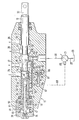
Ein Ausführungsbeispiel der Erfindung ist in der Zeichnung dargestellt und in der nachfolgenden Beschreibung näher erläutert. Sie zeigt einen Längsschnitt durch ein Wegeventil.An embodiment of the invention is shown in the drawing and explained in more detail in the following description. It shows a longitudinal section through a directional valve.
Im Gehäuse 10 eines Wegeventils 11 ist eine Längsbohrung 12 ausgebildet, in der ein Steuerschieber 13 dicht gleitend geführt ist. An der Längsbohrung 12 sind im Abstand voneinander Ringnuten 14 bis 18 ausgebildet, wobei in die Ringnut 16 eine quer zur Längsbohrung 12 verlaufende Einlassbohrung 19 mündet, von der eine Förderleitung 20 zu einer Verstellpumpe 21 führt. Diese saugt über eine Saugleitung 22 Druckmittel aus einem Behälter 23 an. In die Ringnuten 14,18 münden quer zur Längsbohrung 12 verlaufende Bohrungen 25, 26, welche Verbindung zum Behälter 23 haben. Ebensolche Bohrungen 27, 28, welche in die Ringnuten 15, 17 münden, haben Anschluss zu einem nicht dargestellten Verbraucher.A longitudinal bore 12 is formed in the
Am Steuerschieber 13 sind beidseitig eines etwa mittigen Bundes 30 zwei längliche Ringnuten 31, 32 ausgebildet. Der Steuerschieber ragt auf einer Seite aus dem Gehäuse und hat dort einen Anschlusszapfen 33, der an einem nicht dargestellten Hebel angelenkt ist, über welchen der Steuerschieber betätigt wird. Auf der gegenüberliegenden Seite ist das Gehäuse durch eine etwa becherförmig ausgebildete Verschlussschraube 34 verschlossen, welche in das Gehäuse eingeschraubt ist. Auf dieser Seite weist der Steuerschieber 13 eine mittige Sackbohrung 36 auf, in welche ein Differentialkolben 37 taucht, der im Boden 38 der Verschlussschraube geringfügig in axialer und radialer Richtung gelagert ist, damit er sich gegenüber dem Schieber richtig einstellen kann. Der Kolbenteil 37' mit grossem Durchmesser begrenzt den innenliegenden Teil der Sackbohrung 36, welcher einen Druckraum 39 bildet. Von dessen Ende führt eine Querbohrung 40 zu einer kleinen Ringnut 41 an der Aussenseite des Steuerschiebers 13. Von einer der Ringnut 41 benachbarten Ringnut 43 ebenfalls an der Aussenseite des Steuerschiebers führt eine Querbohrung 44 zu einem von dem Differentialkolben 37 und der Sackbohrung 36 gebildeten Druckraum 45.Two elongated
In das Ende der Sackbohrung 36 ist eine Hülse 47 eingeschraubt, die einen aussenliegenden Bund 48 hat, an der sich der Innenrand eines Federtellers 49 anlegt, während dessen Aussenrand am Boden 38 der Verschlussschraube 34 anliegt. Dem Federteller 49 gegenüberliegend befindet sich ebenfalls an der Hülse 47 ein Federteller 50, der mit seiner Innenseite an der Stirnseite des Steuerschiebers anliegt. Zwischen beiden Federtellern liegt eine Druckfeder 51, die zusammen mit den Federtellern in bekannter Weise eine Rückholeinrichtung für den Steuerschieber 13 bildet, d.h. diese stellt den Steuerschieber in die in der Zeichnung dargestellte Neutralstellung, wenn keine Kraft auf den Steuerschieber einwirkt.In the end of the
Von der Ringnut 14 führt ein Kanal 53 in den Bereich der Ringnut 41, wenn sich der Steuerschieber in Neutralstellung befindet. Ebenso führt von der Ringnut 43 ein im Gehäuse 10 verlaufender Kanal 54 zu einer Stelle an der Längsbohrung 12, die nahe an der linken Flanke 16' der Ringnut 16 liegt. Ein dritter Kanal 55 im Gehäuse verläuft ebenfalls von der Ringnut 43 zu einer Stelle an der Längsbohrung 12, die nahe der rechten Flanke 16" der Ringnut 16 liegt. Vom Kanal 55 zweigt eine Bohrung 56 ab, welche an der Ringnut 41 mündet. Vom Kanal 54 geht ein Kanal 57 aus, welcher in eine Gehäusebohrung 58 mit zwei einander gegenüberliegenden Sitzen 59, 60 mündet. In der Bohrung 58 sind zwei kugelige Ventilkörper 62,63 eines Doppelrückschlagventils 61 angeordnet, die durch eine Druckfeder 64 auseinander gedrückt werden. Vom Ventilsitz 60 führt ein im Gehäuse verlaufender Kanal 65 zum Kanal 55. Von der Mitte der Bohrung 58 führt eine Bohrung 66 zu einer quer im Gehäuse 10 verlaufenden Bohrung 67, von welcher eine Steuerleitung 68 zum Druckregler 69 der Pumpe 21 führt.A
Sind mehrere wie oben beschriebene Ventile zu einem Block zusammengebaut, so wird die Bohrung 67 durch alle Ventile verlaufen, und von jeder solchen Bohrung 67 führt eine entsprechende Bohrung 66 zum Doppelrückschlagventil 61.If several valves as described above are assembled to form a block, the
Wird der Steuerschieber 13 nach links verschoben, so wird das von der Pumpe geförderte Druckmittel zur Bohrung 28 weitergeleitet, von der es zum Verbraucher strömt. Dort baut sich je nach Last bzw. Widerstand ein bestimmter Lastdruck auf, der über die Ringnut 17 auch in den Kanal 55 fortgepflanzt wird. Von hier gelangt das Druckmittel unter diesem Lastdruck in die Ringnuten 41,43 und von diesen wiederum über die Bohrungen 40, 44 in die Druckräume 39 und 45 beidseits des Kolbens 37'. Da der Kolben 37 als Differentialkolben ausgebildet ist und in beiden Druckräumen derselbe Druck herrscht - nämlich der Lastdruck - ergibt sich eine resultierende Kraft (nach links) auf den Steuerschieber 13, die der von aussen eingeleiteten Bewegung entgegengerichtet und in ihrer Grösse dem am Verbraucheranschluss 28 herrschenden Lastdruck proportional ist. Damit hat der den Steuerschieber 13 Bedienende ein Gefühl für die zu bewegende Last.If the control slide 13 is moved to the left, the pressure medium conveyed by the pump is passed on to the
Wird der Steuerschieber 13 nach rechts verschoben, so gelangt Druckmittel über die Ringnut 16 zur Ringnut 15 und der dort mündenden Bohrung 27 zum Verbraucher. Der dort sich einstellende Lastdruck pflanzt sich über den Kanal 54 in die Ringnut 43 fort und von hier in den Druckraum 45. Der Druckraum 39 ist zum Rücklauf 25 entlastet, da die Ringnut 41 mit dem Kanal 53 in Verbindung steht. Durch die im Druckraum 45 infolge des Lastdrucks erzeugte Kraft wirkt auf die Stirnfläche der fest mit dem Steuerschieber verbundene Hülse 47, so dass sich eine dem Lastdruck proportionale Kraft entgegen der am Steuerschieber 13 angreifenden Verschiebekraft ergibt. Das Resultat ist dasselbe wie oben beschrieben.If the control slide 13 is moved to the right, pressure medium passes through the
Sind mehrere solche Ventile zu einem Block vereinigt, so wird der höchste Druck der an die Ventile angeschlossenen Verbraucher über die Doppelrückschlagventile 61 ausgewählt und über die Bohrungen 66, 67 in die Steuerleitung 68 übertragen. Der dort herrschende Druck betätigt den Druckregler 69 der Pumpe 21 derart, dass diese auf den höchsten sich einstellenden Verbraucherdruck eingestellt wird.If several such valves are combined to form a block, the highest pressure of the consumers connected to the valves is selected via the
Claims (5)
Applications Claiming Priority (2)
| Application Number | Priority Date | Filing Date | Title |
|---|---|---|---|
| DE19803044420 DE3044420A1 (en) | 1980-11-26 | 1980-11-26 | 2-WAY VALVE |
| DE3044420 | 1980-11-26 |
Publications (2)
| Publication Number | Publication Date |
|---|---|
| EP0052709A1 EP0052709A1 (en) | 1982-06-02 |
| EP0052709B1 true EP0052709B1 (en) | 1984-12-27 |
Family
ID=6117560
Family Applications (1)
| Application Number | Title | Priority Date | Filing Date |
|---|---|---|---|
| EP81107400A Expired EP0052709B1 (en) | 1980-11-26 | 1981-09-18 | Distributing valve |
Country Status (2)
| Country | Link |
|---|---|
| EP (1) | EP0052709B1 (en) |
| DE (2) | DE3044420A1 (en) |
Families Citing this family (4)
| Publication number | Priority date | Publication date | Assignee | Title |
|---|---|---|---|---|
| DE4325772C2 (en) * | 1993-07-31 | 1996-07-11 | Peter Dr Ing Beater | Drive system with a signal transmitter |
| DE19631803B4 (en) * | 1996-08-07 | 2007-08-02 | Bosch Rexroth Aktiengesellschaft | Hydraulic control device |
| DE19646449A1 (en) * | 1996-11-11 | 1998-05-14 | Rexroth Mannesmann Gmbh | Control arrangement for hydraulic equipment, e.g. lifting gear of tractor |
| FR2860008B1 (en) * | 2003-09-24 | 2006-02-10 | Staubli Sa Ets | NEGATIVE RATIERE DRAWING MECHANISM AND WEAVING EQUIPPED WITH SUCH A MECHANISM |
Family Cites Families (3)
| Publication number | Priority date | Publication date | Assignee | Title |
|---|---|---|---|---|
| GB796496A (en) * | 1954-11-02 | 1958-06-11 | British Messier Ltd | Improvements in or relating to fluid pressure servo mechanisms |
| US3152610A (en) * | 1961-09-11 | 1964-10-13 | New York Air Brake Co | Hydraulic device |
| DE1696047B2 (en) * | 1968-02-02 | 1976-12-02 | J. Walter Co, Maschinen Gmbh, 8640 Kronach | HYDRAULICALLY OR PNEUMATICALLY DRIVEN GLASS PRESS |
-
1980
- 1980-11-26 DE DE19803044420 patent/DE3044420A1/en not_active Withdrawn
-
1981
- 1981-09-18 EP EP81107400A patent/EP0052709B1/en not_active Expired
- 1981-09-18 DE DE8181107400T patent/DE3167960D1/en not_active Expired
Also Published As
| Publication number | Publication date |
|---|---|
| DE3044420A1 (en) | 1982-06-16 |
| EP0052709A1 (en) | 1982-06-02 |
| DE3167960D1 (en) | 1985-02-07 |
Similar Documents
| Publication | Publication Date | Title |
|---|---|---|
| DE2027562A1 (en) | Fluid control device | |
| DE2305798A1 (en) | HYDRAULIC CONTROL DEVICE, IN PARTICULAR STEERING DEVICE | |
| DE1128239B (en) | Control slide for double-acting pressure medium operated motors | |
| DE1959764A1 (en) | Pressure compensated control valves for systems operated by a pressure medium | |
| DE2232857C2 (en) | Control device for a hydraulically driven implement | |
| DE2434229B2 (en) | Brake pressure control unit for a vehicle brake system that can be actuated by pressure medium | |
| DE2656056A1 (en) | PISTON PUMP | |
| DE1169746B (en) | Spring-loaded pressure relief valve with a spring-loaded auxiliary valve causing it to be triggered | |
| DE4237932C2 (en) | Volume flow control for automotive hydraulics, in particular for steering devices of motor vehicles | |
| EP0052709B1 (en) | Distributing valve | |
| WO1998005870A1 (en) | Hydraulic control device | |
| DE2648280A1 (en) | LOAD PRESSURE CONTROL | |
| DE3504744C2 (en) | ||
| DE2359755C2 (en) | Hydraulic switching valve | |
| DE19651967A1 (en) | Directional control valve for load-independent control of a hydraulic consumer with regard to direction and speed | |
| DE2701509A1 (en) | HYDRAULIC CONTROL DEVICE FOR AT LEAST TWO CONSUMERS | |
| DE10135298A1 (en) | valve assembly | |
| DE2738463C2 (en) | Hydraulic control device for a preferred first servomotor used for vehicle steering and at least one second servomotor | |
| DE4026849C2 (en) | Valve arrangement for generating a control pressure in a hydraulic system | |
| EP0877169B1 (en) | Hydraulic control device for the load-independent control of a double acting actuator | |
| EP0258587B1 (en) | Hydraulic control device | |
| DE1284237B (en) | Control device with a relief valve and an anti-cavitation or regulating valve | |
| DE3418172C2 (en) | Hydraulic control device | |
| DE3312511A1 (en) | Directional control valve with control lines for indicating the consumer pressure | |
| DE19948390B4 (en) | valve assembly |
Legal Events
| Date | Code | Title | Description |
|---|---|---|---|
| PUAI | Public reference made under article 153(3) epc to a published international application that has entered the european phase |
Free format text: ORIGINAL CODE: 0009012 |
|
| 17P | Request for examination filed |
Effective date: 19810918 |
|
| AK | Designated contracting states |
Designated state(s): DE FR GB IT |
|
| ITF | It: translation for a ep patent filed |
Owner name: STUDIO JAUMANN |
|
| GRAA | (expected) grant |
Free format text: ORIGINAL CODE: 0009210 |
|
| AK | Designated contracting states |
Designated state(s): DE FR GB IT |
|
| REF | Corresponds to: |
Ref document number: 3167960 Country of ref document: DE Date of ref document: 19850207 |
|
| ET | Fr: translation filed | ||
| PLBE | No opposition filed within time limit |
Free format text: ORIGINAL CODE: 0009261 |
|
| STAA | Information on the status of an ep patent application or granted ep patent |
Free format text: STATUS: NO OPPOSITION FILED WITHIN TIME LIMIT |
|
| 26N | No opposition filed | ||
| PG25 | Lapsed in a contracting state [announced via postgrant information from national office to epo] |
Ref country code: GB Effective date: 19880918 |
|
| PG25 | Lapsed in a contracting state [announced via postgrant information from national office to epo] |
Ref country code: FR Free format text: LAPSE BECAUSE OF NON-PAYMENT OF DUE FEES Effective date: 19890531 |
|
| GBPC | Gb: european patent ceased through non-payment of renewal fee | ||
| PG25 | Lapsed in a contracting state [announced via postgrant information from national office to epo] |
Ref country code: DE Effective date: 19890601 |
|
| REG | Reference to a national code |
Ref country code: FR Ref legal event code: ST |