EP0052704A1 - A self adjusting hydraulic tappet for heat engines - Google Patents
A self adjusting hydraulic tappet for heat engines Download PDFInfo
- Publication number
- EP0052704A1 EP0052704A1 EP81107141A EP81107141A EP0052704A1 EP 0052704 A1 EP0052704 A1 EP 0052704A1 EP 81107141 A EP81107141 A EP 81107141A EP 81107141 A EP81107141 A EP 81107141A EP 0052704 A1 EP0052704 A1 EP 0052704A1
- Authority
- EP
- European Patent Office
- Prior art keywords
- fact
- chamber
- seat
- tappet according
- end wall
- Prior art date
- Legal status (The legal status is an assumption and is not a legal conclusion. Google has not performed a legal analysis and makes no representation as to the accuracy of the status listed.)
- Granted
Links
Images
Classifications
-
- F—MECHANICAL ENGINEERING; LIGHTING; HEATING; WEAPONS; BLASTING
- F01—MACHINES OR ENGINES IN GENERAL; ENGINE PLANTS IN GENERAL; STEAM ENGINES
- F01L—CYCLICALLY OPERATING VALVES FOR MACHINES OR ENGINES
- F01L1/00—Valve-gear or valve arrangements, e.g. lift-valve gear
- F01L1/20—Adjusting or compensating clearance
- F01L1/22—Adjusting or compensating clearance automatically, e.g. mechanically
- F01L1/24—Adjusting or compensating clearance automatically, e.g. mechanically by fluid means, e.g. hydraulically
- F01L1/245—Hydraulic tappets
- F01L1/25—Hydraulic tappets between cam and valve stem
Definitions
- the present invention relates to a self adjusting hydraulic tappet, particularly suitable for heat engines in which the control of the valves takes place by means of direct control from the cams without the interposition of rockers; such a tappet is particularly suitable for motors the speed of rotation of which is very high.
- the members which control the opening and closing of the valves in combustion engines that is to say the cam and the tappet
- the cap which is conveniently made of a mat- : erial which wears more readily than that of the cam, becomes worn during operation thus causing a play which prevents the complete opening of the valve. Therefore, it is necessary periodically to effect adjustment with shims and, possibly, replace the cap.
- the conditions of clearance between the cam and the valve vary in the various operating conditions of the engine, such clearance depending on the thermal expansion of the members of the kinematic chain interposed between the cam and the valve.
- a known hydraulic tappet comprises a first cup-shape body axially movable in a corresponding seat formed in the cylinder head of the engine and provided with a bottom wall which can be brought into contact with a cam of a cam shaft, and by a side wall, a second cup-shape body axially movable within the first and provided with a side wall and with an end wall which is able to define a chamber with the said walls of the first cup-shape body; in this chamber there is located a spring which can displace the second cup-shape body axially outwardly with respect to the first, and the end wall of the second cup-shape body is held in contact with the stem of a valve.
- the chamber thus defined is in communication, by means of ducts formed in the said cup-shape bodies, with a source of oil under pressure, and along the said ductsthere are positioned interception members.
- Such interception members are constituted by a resiliently deformable flat plate of substantially annular form located within the said chamber: the inner peripheral circular edge region of the said plate is fixed to the end wall of the second cup-shape body, whilst its outer peripheral part is operable to close the end of the first mentioned duct, which opens into the said chamber.
- the fixing of the.plate to the end wall of the second cup-shape body is normally achieved by means of the said spring located between the end walls of the two cup-shape bodies; for this purpose this spring is formed as a cup spring and has an inner peripheral edge which can abut on the said inner peripheral edge region, and an outer peripheral edge which can abut on the end wall of the said first cup-shape body.
- the described tappet has several disadvantages. Above all, the oil seal of the said interception members is rather critical and therefore these allow a certain quantity of oil to escape from the said chamber with the consequence that these chambers tend to become empty in a short time after the engine has stopped, and to achieve a complete filling of these (a condition to which corresponds complete elimination of clearances) rather extended times are necessary.
- the seal obtained with such interception members is acceptable, then, only if the oil pressure in the chamber itself is rather high and corresponding to that which is achieved only during average running conditions of the engine.
- the assembly constituted by the thin plate of the valve means and by the cup spring which holds this latter in the correct working position includes two resilient members which must have very rigorous forms and dimensions, and which must be positioned in a very precise manner between two cup-shape bodies.
- the seat against which this thin plate rests which is formed on the end wall of the second cup-shape body, and the thin plate itself, must have a very high surface finish and strict tolerances on the form and dimensions in order to be able to cooperate in a correct manner with one another, and therefore these must be subjected to a lapping operation.
- the said thin plate being cyclically deformed, is subjected to fatigue stresses which could bring about breakage of the thin plate itself.
- the object of the present invention is that of providing an hydraulic tappet of the type described with a very simple structure and of secure operation which will therefore be free from the above mentioned disadvantages.
- a self adjusting hydraulic tappet comprising a first element axially movable in a corresponding seat formed in the cylinder head of the engine and provided with at least one end wall which can be brought into contact with a cam of a cam shaft, and, with a side wall, a second element axially movable within a cavity in the first in such a way as to define with it a chamber, and able to come into contact with the stem of a valve, the said chamber being in communication, by means of at least one duct formed in the said elements, with a source of fluid under pressure, and along' the said duct there being located interception members, characterised by the fact that the said interception members include at least one ball which can cooperate with a corresponding seat formed along the said duct for closing the duct itself, the said seat being formed in the said second element in the region thereof in which the said duct opens into the said chamber.
- the tappet of the invention is interposed between a cam 2 of a cam shaft 3 and the stem 4 of a valve normally held, by the action of a spring assembly 5, against the tappet itself.
- Such valve control is of the "direct" type, that is to say it does not have an interposed rocker, and is of a type for which the tappet of the invention is particularly suitable.
- the tappet substantially comprises a first movable element 6 which has the form of a cup-shape body, provided with a substantially flat end wall 7 and with a side wall 8 which is slidable in a corresponding seat 9 formed in the engine block.
- the end wall 7 can include a cap (not illustrated) which can come into contact with the cam 2.
- the tappet further includes a second movable element which, in the case of the embodiment of Figures 1 to 6, also has the form of a cup-shape body 10, slidable within the preceding one, and also provided with a side wall 13 and with an end wall 14 which is able to come into contact with the stem 4 of the valve and to define, with the walls 7 and 8 of the first cup-shape body, a substantially cylindrical chamber 15.
- a second movable element which, in the case of the embodiment of Figures 1 to 6, also has the form of a cup-shape body 10, slidable within the preceding one, and also provided with a side wall 13 and with an end wall 14 which is able to come into contact with the stem 4 of the valve and to define, with the walls 7 and 8 of the first cup-shape body, a substantially cylindrical chamber 15.
- This is in communication with a source of liquid under pressure, normally constituted .by the flow of the engine's lubricating oil, through a channel comprising a first duct 16 formed in the end wall 14 of the second cup-shape body 10 and the axis of which is disposed radially with respect to the wall itself, a second duct 17 formed in the side wall 13 of the same body, which opens into an annular cavity 18 also formed in this wall; holes 19, formed in the side wall 8 of the first cup-shape body 6 put this cavity into communication with another annular cavity 20 formed in the engine block round the outer surface of the wall 8 and connected with the said source of liquid.
- the opening of the passage through the duct 16 in the chamber 15 is controlled by a ball 23 which is able to rest on a corresponding, substantially conical seat 24 the axis of which ' conveniently coincides with that of the end wall 14.
- a ball 23 which is able to rest on a corresponding, substantially conical seat 24 the axis of which ' conveniently coincides with that of the end wall 14.
- a cylindrical cavity 25 housing the ball 23, at least partially, with a predetermined radial play.
- annular raised part 26 constituting a shoulder for the end wall 14 of the other body when this is displaced towards the first body; in this way, even when the second cup-shape body 10 is completely within the first, the two end walls 7 and 14 of the two cup-shape bodies are not incontact with one another, leaving the possibility that the ball 23 may become displaced from the seat 24 even in these conditions.
- the seat 24 for the ball 23 is disposed near the periphery of the End wall 14, and is in communication with the first annular cavity 18 by means of a duct 27 formed in the lateral wall 13 of the second cup-shape body. It is evident that there could be provided, in this end wall, a plurality of seats 24 for corresponding balls 23.
- FIG. 3 there is illustrated a variant of the seat for the ball 23; in this case such seat substantially comprises a conical surface 28 the generatrices of which form a predetermined angle with respect to the axis of the surface itself; such angle, which conveniently lies between 10° and 20°, must not be too small to avoid the possibility of the ball 23 jamming in the conical surface 28.
- FIG. 4 there is shown a variant of the stop means between the two end walls 7 and 14 of the two cup-shape bodies 6 and 10; in this, rather than providing an annular upstanding part 26 on the end wall 7 of the first cup-shape body 6, there is formed a central upstanding portion 29 on the same end wall 7.
- a similar upstanding part for the same purpose could be formed in the end wall 14 of the other cup-shape body rather than on the end wall 7.
- the forms of the first and second elements 6 and 10 are slightly different from those illustrated with reference to the preceding Figures.
- the surface 30 of the end wall 7 of the first cup-shape body 6 is flat, and there is formed a central upstanding part 31 on the end wall 14 of the second cup-shape body 10 which is able to abut against the said surface 30 when the second cup-shape body is in its upper end-of-path position.
- a helical spring 32 (which can, however, be of any other type) which is housed in a corresponding cavity of the wall 14 and which is able to hold the annular upstanding part 31 of the said surface 30 normally spaced from the end wall 7.
- each seat 24 of the associated cylindrical cavity 2 5 and of the related hole 27 are coincident and inclined at a predetermined angle with respect to the axis of the cup-shape body 10 as can be clearly seen in the Figures themselves.
- stop means which, in the case of the .
- FIG. 5 are constituted by a member 34., illustrated in plan view in Figure 9, and substantially comprising a pair of coaxial rings 35, 36 connected by spokes 37; the said member, conveniently made from a resiliently deformable material, can be snap inserted in a corresponding annular groove 38 formed in the annular upstanding part 31 of the second cup-shape body 10.
- the mid-diameter of the ring 36 is chosen in such a way as to coincide substantially with that of the circumference on which the axes of the cavities 25 are located, in such a way that this ring constitutes an axial stop to the movement of the balls 23 in the said cavities.
- the stop means for the balls 23 are formed by radial pegs 39 inserted in corresponding holes in the upstanding part 31
- Figures 5 and 6 may be preferable because they allow large relative displacements of the bodies 6 and 10 without risk of the balls escaping from their seats.
- the first element 6 is constituted by two separate parts, a first part indicated 43 of cup-shape form as was the case for the element 6 of the preceding embodiment, and a second part 4 4, rigidly connected to the first and inserted in the cavity defined by the side wall 45 and end wall 46 of the other part 43.
- the second part 44 substantially comprises a hollow body 47, also provided with a side wall 48 and an end wall 49, as well as an annular projection 50 which can contact the inner surface of the side wall 45 of-the first part 43, and which is provided with lightening holes 50a.
- the second element 10 has a substantially cylindrical form and can slide within the cavity of the hollow body 47 to define with it a chamber 52; conveniently a resilient ring 51 constitutes a stop against downward displacement (as viewed in Figures 7 and 8) of the second element 10 with respect to the first 6.
- the second element 10 is provided with an annular cavity 53 in communication with the groove 20 through at least one hole 54 and an annular groove 54a formed in the annular projection 50, and a hole 55 formed in the side wall 45; the groove 20, in turn, is in communication with a source of liquid under pressure.
- the annular cavity 53 is in communication with the chamber 52 by means of holes 56 formed in the central part of the second element 10 as occurs in the case of the embodiment of Figure 7, or else by means of holes 57 formed in the peripheral part of the same element ( Figure 8).
- a seat 58 for a corresponding ball 59 in the region in which each of the holes 56 or 57 opens out into the chamber 52, there is formed a seat 58 for a corresponding ball 59.
- the shape of each of these seats can be formed in the same way as explained with reference to the preceding embodiments.
- This second embodiment may be preferable to the first if the tappet is made to be mounted on motors of different types having seats 9 for tappets of different diameters.
- the tappets intended for such motors can have identical second elements 10 and first elements 6 with the same structure but a different external diameter; the second parts 44 of such first elements can have the same dimensions with the exception of the outer diameter of the annular projection 50. In this way it will be possible to produce tappets intended for different motors with only the replacement of two of the parts which make up the tappet itself.
- the tappet of the invention has a better behaviour than the prior tappets described, both from the point of view of the elimination of the play between cam and valve during the first operating period of the motor (in which the chamber 15 or 52 is filling with oil), and from the point of view of the discharge of oil from the chamber itself.
- the time required for the filling of this chamber is very small, and much less (equal to about half) than that which is necessary for the filling of the same chamber in the prior art tappets described hereinabove; moreover, a complete filling of this tappet is obtained even if the oil pressure is very low, such as occurs when the engine is running only slowly, and which would not be sufficient to fill the chamber of the prior art tappets discussed above.
- This favourable behaviour is probably due to the perfect sealing action obtained, in any condition of use, by the interception members devised for the tappet of the invention, and by the small influence exerted by the inertia of such members.
- the structure of the tappet described hereinabove is very simple being able to dispense completely with resilient members; moreover, the construction of the component parts thereof does not present technological difficulty, the regions of these parts which must be worked with significant: precision being of very limited extent; in particular, the most sensitive region from this point of view is constituted by the seat 24 (or 58) for the ball 23 (or 59) and this is of limited extent, is easily accessable, and is of a simple and well defined geometric form.
Abstract
Description
- The present invention relates to a self adjusting hydraulic tappet, particularly suitable for heat engines in which the control of the valves takes place by means of direct control from the cams without the interposition of rockers; such a tappet is particularly suitable for motors the speed of rotation of which is very high.
- As is known, the members which control the opening and closing of the valves in combustion engines, that is to say the cam and the tappet, are subjected to wear in that they slide under pressure on one another, and in particular an element of the tappet, the cap, which is conveniently made of a mat- : erial which wears more readily than that of the cam, becomes worn during operation thus causing a play which prevents the complete opening of the valve. Therefore, it is necessary periodically to effect adjustment with shims and, possibly, replace the cap. Moreover, the conditions of clearance between the cam and the valve vary in the various operating conditions of the engine, such clearance depending on the thermal expansion of the members of the kinematic chain interposed between the cam and the valve. There exist, however, mechanisms which adjust the clearance in a continuous and automatic manner as soon as it occurs: these are situated on the tappet and are substantially of hydraulic type.
- A known hydraulic tappet comprises a first cup-shape body axially movable in a corresponding seat formed in the cylinder head of the engine and provided with a bottom wall which can be brought into contact with a cam of a cam shaft, and by a side wall, a second cup-shape body axially movable within the first and provided with a side wall and with an end wall which is able to define a chamber with the said walls of the first cup-shape body; in this chamber there is located a spring which can displace the second cup-shape body axially outwardly with respect to the first, and the end wall of the second cup-shape body is held in contact with the stem of a valve. The chamber thus defined is in communication, by means of ducts formed in the said cup-shape bodies, with a source of oil under pressure, and along the said ductsthere are positioned interception members.
- Such interception members are constituted by a resiliently deformable flat plate of substantially annular form located within the said chamber: the inner peripheral circular edge region of the said plate is fixed to the end wall of the second cup-shape body, whilst its outer peripheral part is operable to close the end of the first mentioned duct, which opens into the said chamber. The fixing of the.plate to the end wall of the second cup-shape body is normally achieved by means of the said spring located between the end walls of the two cup-shape bodies; for this purpose this spring is formed as a cup spring and has an inner peripheral edge which can abut on the said inner peripheral edge region, and an outer peripheral edge which can abut on the end wall of the said first cup-shape body.
- The described tappet has several disadvantages. Above all, the oil seal of the said interception members is rather critical and therefore these allow a certain quantity of oil to escape from the said chamber with the consequence that these chambers tend to become empty in a short time after the engine has stopped, and to achieve a complete filling of these (a condition to which corresponds complete elimination of clearances) rather extended times are necessary. The seal obtained with such interception members is acceptable, then, only if the oil pressure in the chamber itself is rather high and corresponding to that which is achieved only during average running conditions of the engine.
- Moreover the structure of the tappet is complex and therefore it is expensive and not very reliable. In fact, above all, the assembly constituted by the thin plate of the valve means and by the cup spring which holds this latter in the correct working position, includes two resilient members which must have very rigorous forms and dimensions, and which must be positioned in a very precise manner between two cup-shape bodies. In addition the seat against which this thin plate rests, which is formed on the end wall of the second cup-shape body, and the thin plate itself, must have a very high surface finish and strict tolerances on the form and dimensions in order to be able to cooperate in a correct manner with one another, and therefore these must be subjected to a lapping operation. Finally, the said thin plate, being cyclically deformed, is subjected to fatigue stresses which could bring about breakage of the thin plate itself.
- The object of the present invention is that of providing an hydraulic tappet of the type described with a very simple structure and of secure operation which will therefore be free from the above mentioned disadvantages.
- According to the present invention there is provided a self adjusting hydraulic tappet comprising a first element axially movable in a corresponding seat formed in the cylinder head of the engine and provided with at least one end wall which can be brought into contact with a cam of a cam shaft, and, with a side wall, a second element axially movable within a cavity in the first in such a way as to define with it a chamber, and able to come into contact with the stem of a valve, the said chamber being in communication, by means of at least one duct formed in the said elements, with a source of fluid under pressure, and along' the said duct there being located interception members, characterised by the fact that the said interception members include at least one ball which can cooperate with a corresponding seat formed along the said duct for closing the duct itself, the said seat being formed in the said second element in the region thereof in which the said duct opens into the said chamber.
- For a better understanding of the tappet of the present invention several embodiments of it will now be described with reference to the attached drawings, in which:
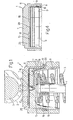
- Figure 1 is a longitudinal section of a first embodiment of the tappet of the invention;
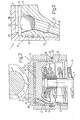
- Figure 2 is a section similar to that of the preceding Figure, of a second embodiment;
- Figures 3 and 4 show, in detail, two variants of the tappet of the preceding Figures;
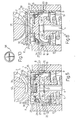
- Figures 5 and 6 show another two variants of the tappet of the preceding Figures;
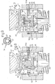
- Figures 7 and 8 show another two embodiments of the tappet of the invention; and
- Figures 9 and 10 show stop members with which the tappet of the present invention is provided.
- The tappet of the invention, indicated with the
reference numeral 1, is interposed between acam 2 of acam shaft 3 and thestem 4 of a valve normally held, by the action of aspring assembly 5, against the tappet itself. Such valve control is of the "direct" type, that is to say it does not have an interposed rocker, and is of a type for which the tappet of the invention is particularly suitable. The tappet substantially comprises a firstmovable element 6 which has the form of a cup-shape body, provided with a substantially flat end wall 7 and with aside wall 8 which is slidable in acorresponding seat 9 formed in the engine block. Conveniently, the end wall 7 can include a cap (not illustrated) which can come into contact with thecam 2. The tappet further includes a second movable element which, in the case of the embodiment of Figures 1 to 6, also has the form of a cup-shape body 10, slidable within the preceding one, and also provided with aside wall 13 and with anend wall 14 which is able to come into contact with thestem 4 of the valve and to define, with thewalls 7 and 8 of the first cup-shape body, a substantiallycylindrical chamber 15. - This is in communication with a source of liquid under pressure, normally constituted .by the flow of the engine's lubricating oil, through a channel comprising a
first duct 16 formed in theend wall 14 of the second cup-shape body 10 and the axis of which is disposed radially with respect to the wall itself, a second duct 17 formed in theside wall 13 of the same body, which opens into anannular cavity 18 also formed in this wall;holes 19, formed in theside wall 8 of the first cup-shape body 6 put this cavity into communication with anotherannular cavity 20 formed in the engine block round the outer surface of thewall 8 and connected with the said source of liquid. - In accordance with the invention the opening of the passage through the
duct 16 in thechamber 15 is controlled by aball 23 which is able to rest on a corresponding, substantiallyconical seat 24 the axis of which ' conveniently coincides with that of theend wall 14. In the embodiment of Figure 1, coaxial with theseat 24 there is formed acylindrical cavity 25 housing theball 23, at least partially, with a predetermined radial play. - Conveniently, on the end wall 7 of the first cup-
shape body 6 there is formed an annular raisedpart 26 constituting a shoulder for theend wall 14 of the other body when this is displaced towards the first body; in this way, even when the second cup-shape body 10 is completely within the first, the twoend walls 7 and 14 of the two cup-shape bodies are not incontact with one another, leaving the possibility that theball 23 may become displaced from theseat 24 even in these conditions. - In the embodiment of Figure 2, the
seat 24 for theball 23 is disposed near the periphery of theEnd wall 14, and is in communication with the firstannular cavity 18 by means of aduct 27 formed in thelateral wall 13 of the second cup-shape body. It is evident that there could be provided, in this end wall, a plurality ofseats 24 forcorresponding balls 23. - In the detail of Figure 3 there is illustrated a variant of the seat for the
ball 23; in this case such seat substantially comprises aconical surface 28 the generatrices of which form a predetermined angle with respect to the axis of the surface itself; such angle, which conveniently lies between 10° and 20°, must not be too small to avoid the possibility of theball 23 jamming in theconical surface 28. - In Figure 4 there is shown a variant of the stop means between the two
end walls 7 and 14 of the two cup-shape bodies upstanding part 26 on the end wall 7 of the first cup-shape body 6, there is formed a centralupstanding portion 29 on the same end wall 7. Obviously, a similar upstanding part for the same purpose could be formed in theend wall 14 of the other cup-shape body rather than on the end wall 7. , - In the embodiment of Figures 5 and 6 the forms of the first and
second elements surface 30 of the end wall 7 of the first cup-shape body 6 is flat, and there is formed a centralupstanding part 31 on theend wall 14 of the second cup-shape body 10 which is able to abut against the saidsurface 30 when the second cup-shape body is in its upper end-of-path position. In the embodiment of Figure 5 there is provided a helical spring 32 (which can, however, be of any other type) which is housed in a corresponding cavity of thewall 14 and which is able to hold the annularupstanding part 31 of the saidsurface 30 normally spaced from the end wall 7. - In the two embodiments of Figures 5 and 6 the axes of each
seat 24 of the associatedcylindrical cavity 25 and of therelated hole 27 are coincident and inclined at a predetermined angle with respect to the axis of the cup-shape body 10 as can be clearly seen in the Figures themselves. For the purpose of preventing theball 23 from being able to escape from the associatedcavity 25 there are fitted stop means which, in the case of the . embodiment of Figure 5, are constituted by a member 34., illustrated in plan view in Figure 9, and substantially comprising a pair ofcoaxial rings spokes 37; the said member, conveniently made from a resiliently deformable material, can be snap inserted in a correspondingannular groove 38 formed in the annularupstanding part 31 of the second cup-shape body 10. The mid-diameter of thering 36 is chosen in such a way as to coincide substantially with that of the circumference on which the axes of thecavities 25 are located, in such a way that this ring constitutes an axial stop to the movement of theballs 23 in the said cavities. - In the case of the embodiment of Figure 6, the stop means for the
balls 23 are formed byradial pegs 39 inserted in corresponding holes in theupstanding part 31 - The embodiments of Figures 5 and 6 may be preferable because they allow large relative displacements of the
bodies - In the embodiment of Figures 7 and 8 the
first element 6 is constituted by two separate parts, a first part indicated 43 of cup-shape form as was the case for theelement 6 of the preceding embodiment, and asecond part 44, rigidly connected to the first and inserted in the cavity defined by theside wall 45 andend wall 46 of theother part 43. - The second part 44 substantially comprises a
hollow body 47, also provided with aside wall 48 and anend wall 49, as well as anannular projection 50 which can contact the inner surface of theside wall 45 of-thefirst part 43, and which is provided withlightening holes 50a. - The
second element 10 has a substantially cylindrical form and can slide within the cavity of thehollow body 47 to define with it achamber 52; conveniently aresilient ring 51 constitutes a stop against downward displacement (as viewed in Figures 7 and 8) of thesecond element 10 with respect to the first 6. - The
second element 10 is provided with anannular cavity 53 in communication with thegroove 20 through at least one hole 54 and anannular groove 54a formed in theannular projection 50, and ahole 55 formed in theside wall 45; thegroove 20, in turn, is in communication with a source of liquid under pressure. - The
annular cavity 53 is in communication with thechamber 52 by means of holes 56 formed in the central part of thesecond element 10 as occurs in the case of the embodiment of Figure 7, or else by means of holes 57 formed in the peripheral part of the same element (Figure 8). In both these cases, in the region in which each of the holes 56 or 57 opens out into thechamber 52, there is formed aseat 58 for acorresponding ball 59. The shape of each of these seats can be formed in the same way as explained with reference to the preceding embodiments. - ; In this case also there may be provided stop means for the
balls 59, snap-engageable in annular grooves of theelement 10 formed on a circular projection of the element itself (Figure 8) or in a circular recess thereof; the member utilised in this second case can have, in plan, the form illustrated in Figure 10. - The tappet described above operates in the following way; this is considered first with reference to the first embodiment shown in Figures 1,2,5 and 6.
- When the tappet is in the rest condition there is no liquid in the chamber 15 (or only a small quantity at atmospheric pressure), this having left the chamber itself by seeping through the annular spaces between the facing surfaces of the
side walls shape bodies annular cavity 20 of the engine block and, from this, through theholes 19, theannular cavity 18 and theducts 16 and 17 (or 27) reaches theseat 24 closed by theball 23. Since this ball rests only under the action of its own weight on the seat it rises allowing the oil to enter into thechamber 15. The quantity of oil which enters this chamber is that which is necessary to axially space the two cup-shape bodies from one another a distance sufficient to eliminate the clearance between the tappet and thecam 2. - While the valve is opening, because of the force applied to the tappet from the
cam 2, the oil pressure within thechamber 15 increases and consequently presses theball 24 against the associatedseat 23, preventing the escape of oil from the chamber; in this phase, therefore, the oil contained in the chamber acts as a hydraulic bearing able to maintain the two cup-shape bodies in their cor-. rect relative axial positions. - The operation of the embodiment of the tappet shown in Figures 7 and 8 is entirely identical to that described with reference to the preceding embodiment. In this case, the oil from the
annular groove 20 arrives in thechamber 52 within thehollow body 47 through theholes 55, theannular groove 54a, the hole 54 and theannular cavity 53, and from there traverses the holes 56 (or 57) in such a way as to press thesecond element 10 against thestem 4 of the valve and thefirst element 6 against thecam 2. - This second embodiment may be preferable to the first if the tappet is made to be mounted on motors of different
types having seats 9 for tappets of different diameters. In fact, the tappets intended for such motors can have identicalsecond elements 10 andfirst elements 6 with the same structure but a different external diameter; the second parts 44 of such first elements can have the same dimensions with the exception of the outer diameter of theannular projection 50. In this way it will be possible to produce tappets intended for different motors with only the replacement of two of the parts which make up the tappet itself. - It is apparent that the springs, such as the
spring 32, interposed between the twoelements balls - It has been found that the tappet of the invention has a better behaviour than the prior tappets described, both from the point of view of the elimination of the play between cam and valve during the first operating period of the motor (in which the
chamber - In fact, the time required for the filling of this chamber is very small, and much less (equal to about half) than that which is necessary for the filling of the same chamber in the prior art tappets described hereinabove; moreover, a complete filling of this tappet is obtained even if the oil pressure is very low, such as occurs when the engine is running only slowly, and which would not be sufficient to fill the chamber of the prior art tappets discussed above. This favourable behaviour is probably due to the perfect sealing action obtained, in any condition of use, by the interception members devised for the tappet of the invention, and by the small influence exerted by the inertia of such members. It has also been found that this sealing action is improved and much greater than that obtainable with other interception members even in the absence of pressure in the chamber 15 (or 52), a condition which occurs when the engine is stopped; therefore in such conditions the chamber empties only after a long time, due to the seepage which takes place between the lateral sliding surfaces of the two
elements - It will apparent, then, that the structure of the tappet described hereinabove is very simple being able to dispense completely with resilient members; moreover, the construction of the component parts thereof does not present technological difficulty, the regions of these parts which must be worked with significant: precision being of very limited extent; in particular, the most sensitive region from this point of view is constituted by the seat 24 (or 58) for the ball 23 (or 59) and this is of limited extent, is easily accessable, and is of a simple and well defined geometric form.
- Because of its very simple structure the operation of the tappet is certain even over long periods of use, there- being no member which resiliently deformsduring the operation and which could therefore give rise to breakages due to fatigue.
- It is clear that the various parts of the tappet of the present invention described hereinabove can be modified or varied without by this departing from the scope of the present invention.
Claims (13)
Applications Claiming Priority (2)
| Application Number | Priority Date | Filing Date | Title |
|---|---|---|---|
| IT68785/80A IT1129888B (en) | 1980-11-21 | 1980-11-21 | HYDRAULIC TAPPETS WITH AUTOMATIC RESUME OF GAME FOR ENDOTHERMAL ENGINES |
| IT6878580 | 1980-11-21 |
Publications (2)
| Publication Number | Publication Date |
|---|---|
| EP0052704A1 true EP0052704A1 (en) | 1982-06-02 |
| EP0052704B1 EP0052704B1 (en) | 1986-04-16 |
Family
ID=11310576
Family Applications (1)
| Application Number | Title | Priority Date | Filing Date |
|---|---|---|---|
| EP81107141A Expired EP0052704B1 (en) | 1980-11-21 | 1981-09-10 | A self adjusting hydraulic tappet for heat engines |
Country Status (9)
| Country | Link |
|---|---|
| US (2) | US4424774A (en) |
| EP (1) | EP0052704B1 (en) |
| JP (1) | JPS57116114A (en) |
| AR (1) | AR227448A1 (en) |
| BR (1) | BR8107443A (en) |
| DE (1) | DE3174406D1 (en) |
| ES (1) | ES507357A0 (en) |
| IT (1) | IT1129888B (en) |
| MX (1) | MX154946A (en) |
Cited By (3)
| Publication number | Priority date | Publication date | Assignee | Title |
|---|---|---|---|---|
| FR2533967A1 (en) * | 1982-10-05 | 1984-04-06 | Riv Officine Di Villar Perosa | GAME COMPENSATOR DEVICE THAT CAN BE INSERTED IN A DRIVE CHAIN FOR CONTROLLING A VALVE IN AN EXPLOSION ENGINE |
| EP0160287A2 (en) * | 1984-05-03 | 1985-11-06 | RIV-SKF OFFICINE DI VILLAR PEROSA S.p.A | Perfected hydraulic tappet with automatic slack take-up for internal combustion engines |
| EP0179398A2 (en) * | 1984-10-25 | 1986-04-30 | FIAT AUTO S.p.A. | Hydraulic tappet |
Families Citing this family (8)
| Publication number | Priority date | Publication date | Assignee | Title |
|---|---|---|---|---|
| JPS5934005U (en) * | 1982-08-30 | 1984-03-02 | トヨタ自動車株式会社 | internal combustion engine hydraulic lifter |
| JPS6110907U (en) * | 1984-06-26 | 1986-01-22 | 株式会社アツギユニシア | Lush adjustment device in the valve train of an internal combustion engine |
| DE3920729A1 (en) * | 1989-06-24 | 1991-01-10 | Gmb Giesserei & Maschinenbau B | CUPS FOR BOTTLE VALVES |
| JPH0330514U (en) * | 1989-08-02 | 1991-03-26 | ||
| JPH0434407U (en) * | 1990-07-19 | 1992-03-23 | ||
| DE4023885A1 (en) * | 1990-07-27 | 1992-01-30 | Bayerische Motoren Werke Ag | ROLLER TOWEL WITH HYDRAULIC VALVE COMPENSATION |
| US5088458A (en) * | 1991-02-01 | 1992-02-18 | Siemens Automotive L.P. | Lash adjusted for engine valve actuator assembly |
| DE102005029831A1 (en) * | 2004-07-23 | 2006-03-16 | Ina-Schaeffler Kg | Hydraulic valve-lash-adjusting element for engine valve train, has valve shutter virtually stationary within piston which is moved relative to shutter to control upper and lower ports in piston |
Citations (4)
| Publication number | Priority date | Publication date | Assignee | Title |
|---|---|---|---|---|
| US2158222A (en) * | 1936-11-17 | 1939-05-16 | Ernest L Dayton | Compensating valve mechanism |
| GB909707A (en) * | 1958-02-05 | 1962-10-31 | Renault | Improvements in or relating to hydraulic devices for taking up axial play in valve gears, notably of internal combustion engines |
| DE1808000A1 (en) * | 1968-11-09 | 1970-05-27 | Richard Kuechen Sen | Hydraulic, automatically working valve clearance compensation device |
| FR2141025A5 (en) * | 1971-03-08 | 1973-01-19 | Eaton Corp |
Family Cites Families (9)
| Publication number | Priority date | Publication date | Assignee | Title |
|---|---|---|---|---|
| US2237854A (en) * | 1934-06-04 | 1941-04-08 | Eaton Mfg Co | Compensating hydraulic valve tappet for internal combustion engines |
| US2870755A (en) * | 1956-05-14 | 1959-01-27 | Ernest L Dayton | Hydraulic valve tappet |
| GB1241634A (en) * | 1968-04-19 | 1971-08-04 | Motomak | Valve tappet for engines having an overhead camshaft |
| US3521608A (en) * | 1968-10-16 | 1970-07-28 | Gen Motors Corp | Self-contained hydraulic valve lifter |
| JPS5329410A (en) * | 1976-08-30 | 1978-03-18 | Toyota Motor Corp | Hydraulic valve lifter assembly for overhead cam type engine |
| DE2758957A1 (en) * | 1977-12-30 | 1979-07-05 | Wizemann Gmbh U Co J | Hydraulic tappet for IC engine valve - has actuating piston cylinder integral with oil reservoir and peripheral plates welded on to form top and bottom |
| DE2829423A1 (en) * | 1978-07-05 | 1980-01-17 | Irm Antriebstech Gmbh | Hydraulically compensated valve pusher for overhead cam engine - has different material insert and guide secured to avoid oil filled cavity |
| DE2847699C3 (en) * | 1978-11-03 | 1982-03-04 | Kamax-Werke Rudolf Kellermann Gmbh & Co Kg, 3360 Osterode | Hydraulic lash adjuster |
| IT7853889V0 (en) * | 1978-11-15 | 1978-11-15 | Fiat Spa | HYDRAULIC PUNTERS WITH AUTOMATIC BACKLASH FOR INTERNAL COMBUSTION ENGINES WITH CAMSHAFTS IN THE HEAD |
-
1980
- 1980-11-21 IT IT68785/80A patent/IT1129888B/en active
-
1981
- 1981-09-10 EP EP81107141A patent/EP0052704B1/en not_active Expired
- 1981-09-10 DE DE8181107141T patent/DE3174406D1/en not_active Expired
- 1981-09-17 US US06/303,053 patent/US4424774A/en not_active Expired - Lifetime
- 1981-11-17 BR BR8107443A patent/BR8107443A/en not_active IP Right Cessation
- 1981-11-19 JP JP56186781A patent/JPS57116114A/en active Granted
- 1981-11-19 MX MX190209A patent/MX154946A/en unknown
- 1981-11-20 ES ES507357A patent/ES507357A0/en active Granted
- 1981-11-20 AR AR287553A patent/AR227448A1/en active
-
1984
- 1984-01-09 US US06/569,512 patent/US4530320A/en not_active Expired - Lifetime
Patent Citations (4)
| Publication number | Priority date | Publication date | Assignee | Title |
|---|---|---|---|---|
| US2158222A (en) * | 1936-11-17 | 1939-05-16 | Ernest L Dayton | Compensating valve mechanism |
| GB909707A (en) * | 1958-02-05 | 1962-10-31 | Renault | Improvements in or relating to hydraulic devices for taking up axial play in valve gears, notably of internal combustion engines |
| DE1808000A1 (en) * | 1968-11-09 | 1970-05-27 | Richard Kuechen Sen | Hydraulic, automatically working valve clearance compensation device |
| FR2141025A5 (en) * | 1971-03-08 | 1973-01-19 | Eaton Corp |
Cited By (6)
| Publication number | Priority date | Publication date | Assignee | Title |
|---|---|---|---|---|
| FR2533967A1 (en) * | 1982-10-05 | 1984-04-06 | Riv Officine Di Villar Perosa | GAME COMPENSATOR DEVICE THAT CAN BE INSERTED IN A DRIVE CHAIN FOR CONTROLLING A VALVE IN AN EXPLOSION ENGINE |
| GB2130673A (en) * | 1982-10-05 | 1984-06-06 | Riv Officine Di Villar Perosa | Hydraulic lash adjuster |
| EP0160287A2 (en) * | 1984-05-03 | 1985-11-06 | RIV-SKF OFFICINE DI VILLAR PEROSA S.p.A | Perfected hydraulic tappet with automatic slack take-up for internal combustion engines |
| EP0160287A3 (en) * | 1984-05-03 | 1987-01-14 | RIV-SKF OFFICINE DI VILLAR PEROSA S.p.A | Perfected hydraulic tappet with automatic slack take-up for internal combustion engines |
| EP0179398A2 (en) * | 1984-10-25 | 1986-04-30 | FIAT AUTO S.p.A. | Hydraulic tappet |
| EP0179398A3 (en) * | 1984-10-25 | 1987-04-15 | Fiat Auto S.P.A. | Oleodynamic valve, particularly for a hydraulic tappet |
Also Published As
| Publication number | Publication date |
|---|---|
| IT1129888B (en) | 1986-06-11 |
| AR227448A1 (en) | 1982-10-29 |
| JPH0321721B2 (en) | 1991-03-25 |
| IT8068785A0 (en) | 1980-11-21 |
| DE3174406D1 (en) | 1986-05-22 |
| JPS57116114A (en) | 1982-07-20 |
| ES8302191A1 (en) | 1982-12-16 |
| US4424774A (en) | 1984-01-10 |
| MX154946A (en) | 1988-01-11 |
| EP0052704B1 (en) | 1986-04-16 |
| BR8107443A (en) | 1982-08-10 |
| US4530320A (en) | 1985-07-23 |
| ES507357A0 (en) | 1982-12-16 |
Similar Documents
| Publication | Publication Date | Title |
|---|---|---|
| EP2441928B1 (en) | Hydraulic lash adjuster for internal combustion engine | |
| US4424774A (en) | Self adjusting hydraulic tappet for heat engines | |
| US5901676A (en) | Hydraulic lash compensator | |
| EP1298287B1 (en) | Hydraulic lash adjuster & Biased normally open check valve system therefor | |
| US4788947A (en) | Cap retainer for hydraulic lash adjuster | |
| CA1207200A (en) | Hydraulic lash adjuster oil metering ball valve | |
| KR100299302B1 (en) | Valve control means | |
| US3572299A (en) | Valve-actuating train for machinery having a cyclicly operated poppet valve | |
| US3704696A (en) | Hydraulic valve lifter | |
| EP0462568A1 (en) | Timing system, particularly for an internal combustion engine with a number of valves per cylinder | |
| EP0145445B1 (en) | Self-contained hydraulic bucket lifter | |
| KR20000062262A (en) | Tappet for a valve mechanism of an internal combustion engine | |
| US5673657A (en) | Direct-acting hydraulic tappet with roller follower | |
| US3728990A (en) | Hydraulic tappets for internal combustion engines | |
| US3989016A (en) | Mechanical valve lifter | |
| US4688526A (en) | Self-contained hydraulic bucket lifter | |
| US4779583A (en) | Cup-type tappets for use in internal combustion engines | |
| US4649875A (en) | Oiltight hydraulic tappet for controlling an internal combustion engine valve | |
| US3439659A (en) | Spiral metering valve | |
| US3014472A (en) | Hydraulic valve tappet | |
| US2880710A (en) | Self adjusting tappets | |
| US2882878A (en) | Self-aligning tappet | |
| EP0179398B1 (en) | Hydraulic tappet | |
| EP0681092A1 (en) | A valve control device for an internal combustion engine having a tappet clearance compensation device | |
| GB2088005A (en) | A self adjusting hydraulic tappet for a heat engine particularly a heat engine having valves controlled by means of rockers |
Legal Events
| Date | Code | Title | Description |
|---|---|---|---|
| PUAI | Public reference made under article 153(3) epc to a published international application that has entered the european phase |
Free format text: ORIGINAL CODE: 0009012 |
|
| AK | Designated contracting states |
Designated state(s): DE FR GB SE |
|
| 17P | Request for examination filed |
Effective date: 19821019 |
|
| GRAA | (expected) grant |
Free format text: ORIGINAL CODE: 0009210 |
|
| AK | Designated contracting states |
Kind code of ref document: B1 Designated state(s): DE FR GB SE |
|
| PG25 | Lapsed in a contracting state [announced via postgrant information from national office to epo] |
Ref country code: SE Effective date: 19860430 |
|
| REF | Corresponds to: |
Ref document number: 3174406 Country of ref document: DE Date of ref document: 19860522 |
|
| ET | Fr: translation filed | ||
| PLBE | No opposition filed within time limit |
Free format text: ORIGINAL CODE: 0009261 |
|
| STAA | Information on the status of an ep patent application or granted ep patent |
Free format text: STATUS: NO OPPOSITION FILED WITHIN TIME LIMIT |
|
| 26N | No opposition filed | ||
| PGFP | Annual fee paid to national office [announced via postgrant information from national office to epo] |
Ref country code: SE Payment date: 19920914 Year of fee payment: 12 |
|
| PGFP | Annual fee paid to national office [announced via postgrant information from national office to epo] |
Ref country code: FR Payment date: 20000822 Year of fee payment: 20 |
|
| PGFP | Annual fee paid to national office [announced via postgrant information from national office to epo] |
Ref country code: GB Payment date: 20000825 Year of fee payment: 20 |
|
| PGFP | Annual fee paid to national office [announced via postgrant information from national office to epo] |
Ref country code: DE Payment date: 20000828 Year of fee payment: 20 |
|
| PG25 | Lapsed in a contracting state [announced via postgrant information from national office to epo] |
Ref country code: GB Free format text: LAPSE BECAUSE OF EXPIRATION OF PROTECTION Effective date: 20010909 |
|
| REG | Reference to a national code |
Ref country code: GB Ref legal event code: PE20 Effective date: 20010909 |