EP0052570B1 - Vorrichtung zum Prüfen des Inneren eines Kernreaktor-Druckgefässes - Google Patents
Vorrichtung zum Prüfen des Inneren eines Kernreaktor-Druckgefässes Download PDFInfo
- Publication number
- EP0052570B1 EP0052570B1 EP81401817A EP81401817A EP0052570B1 EP 0052570 B1 EP0052570 B1 EP 0052570B1 EP 81401817 A EP81401817 A EP 81401817A EP 81401817 A EP81401817 A EP 81401817A EP 0052570 B1 EP0052570 B1 EP 0052570B1
- Authority
- EP
- European Patent Office
- Prior art keywords
- cabin
- tank
- module according
- intervention module
- tool
- Prior art date
- Legal status (The legal status is an assumption and is not a legal conclusion. Google has not performed a legal analysis and makes no representation as to the accuracy of the status listed.)
- Expired
Links
Images


Classifications
-
- G—PHYSICS
- G21—NUCLEAR PHYSICS; NUCLEAR ENGINEERING
- G21C—NUCLEAR REACTORS
- G21C17/00—Monitoring; Testing ; Maintaining
- G21C17/003—Remote inspection of vessels, e.g. pressure vessels
- G21C17/01—Inspection of the inner surfaces of vessels
-
- Y—GENERAL TAGGING OF NEW TECHNOLOGICAL DEVELOPMENTS; GENERAL TAGGING OF CROSS-SECTIONAL TECHNOLOGIES SPANNING OVER SEVERAL SECTIONS OF THE IPC; TECHNICAL SUBJECTS COVERED BY FORMER USPC CROSS-REFERENCE ART COLLECTIONS [XRACs] AND DIGESTS
- Y02—TECHNOLOGIES OR APPLICATIONS FOR MITIGATION OR ADAPTATION AGAINST CLIMATE CHANGE
- Y02E—REDUCTION OF GREENHOUSE GAS [GHG] EMISSIONS, RELATED TO ENERGY GENERATION, TRANSMISSION OR DISTRIBUTION
- Y02E30/00—Energy generation of nuclear origin
- Y02E30/30—Nuclear fission reactors
Definitions
- the present invention relates to an intervention module inside a nuclear reactor vessel, and more particularly inside a pressurized water reactor vessel when the latter has been at least partially emptied of its components. internal.
- the present invention allows the realization of a versatile module allowing, inside a tank become radioactive, the main verification and maintenance operations under the dependence and direct control of an operator, and without discomfort for this one.
- the rotating part comprises a diametrical beam provided with raceways on which the cabin rests, with means for moving the cabin on the beam radially with respect to the tank and, on the outer wall of a face provided with '' a porthole, the cabin comprises a tool-carrying arm, mounted cantilevered on a turntable around an axis perpendicular to the face of the cabin, the turntable itself being carried by a carriage movable in two directions perpendicular in a plane parallel to the face of the cabin, with means controlled from inside the cabin to move the carriage and orient the arm on it.
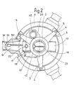
- a star support frame 1 consisting of a central cylindrical barrel 2, and three branches 3 each carrying at its end a fitting sleeve in place 4.
- the sockets 4 are engaged on centering guides 5 mounted on the flange 6 for fixing the tank cover.
- a diametral rib 7, provided with a sling orifice 8, is integral with the central shaft 2 of the frame.
- a diametrical beam 10 is suspended from the frame 1 by means of a ball ring 11, centered on the axis of the tank when the frame 1 is in position on the flange 6 of the tank.
- a brake gear motor group 12 fixed on internal ribs of the barrel 2, carries a pinion 13 at the end of the shaft which meshes with a conjugate toothed crown secured to the beam 10. The actuation of the motor 12 therefore causes the rotation of the beam 10 relative to the frame 1, and therefore relative to the tank.
- An indexing cylinder 14 is used to immobilize the rotating beam 10 in precise predetermined positions.
- the beam 10 comprises two lateral wings 16 which each serve as a raceway for four rollers 17 joined together in pairs by spreaders 18 articulated at 19 on parts integral with a cabin 20.
- the cabin 20, which constitutes the module intervention proper, is thus suspended from the beam 10, on which it can be moved longitudinally, that is to say radially with respect to the tank.
- the beam is provided with a geared motor group 22 which rotates a screw 23 carried by two bearings 24 integral with the floor of the beam 10.
- This floor has a longitudinal light 25 which allows the displacement of a candle 26 secured to the roof of the cabin, and carrying a fixed nut engaged on the screw 23, the actuation of the motor 22 therefore causes the rotation of the screw 23 in one direction or the other, and thereby the longitudinal displacement of the jack 26 and of the cabin 20 which rolls on the rails 16 by its rollers 17.
- the cabin 20, of internal dimensions allowing the easy evolution of at least one operator, has all its walls of material ensuring good protection against radiation, and for example a sandwich composed of two stainless steel sheets enclosing a lead filling .
- the external vision is ensured by a porthole 28 of large dimensions on the front face which will constitute the main working face, and by rear or side portholes 29 of smaller surface.
- the portholes are made of very thick lead glass, ensuring the same degree of protection as the opaque walls.
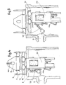
- FIG. 3 shows in more detail the assembly of the tool-carrying arm 30 and means for adjusting its position on the front face of the cabin.
- the tool-carrying arm shown here is specially intended for working in one of the connection pipes of the primary circuit and for this has at its free end a centering pad 31.
- the tool properly said is shown here only symbolically at 32, because it can be as required, for example grinding equipment, welding, or ultrasonic control.
- the arm 30, the tool drive members of which are protected here by a bellows, is articulated at 33 on a portion 34 in the form of a yoke formed on a rotating plate 35.
- the plate 35 is perforated in its center, and can pivot by a ball crown on a fixed plate 36 also perforated in its center.
- the plate 36 is integral with a frame 37-38, the two end tubular elements 37 and 38 of which respectively enclose a smooth tube and a screw 39.
- the geared motor group 40 drives a nut engaged on the screw 39, such so that the actuation of the motor 40 allows the vertical displacement of the entire frame 37-38, and consequently of the arm 30.
- the vertical guides of the frame 37-38 are carried by supports 42, which likewise enclose two horizontal guides 43 and 44, respectively a smooth tube and a screw.
- the geared motor group 45 by means of a nut engaged on the screw 44, allows the transverse movement of the assembly. It can be seen that the arm 30 can thus be brought into any position, inclination and orientation over a large part of the working front face of the cabin 20.
- the porthole 28 which occupies almost the whole of this face allows great visibility from the inside the cabin, including in the area near the axis of the arm thanks to the openings in the trays 35 and 36.
- the chimney 47 for staff access shown here after connection to the flange 48 on the cabin ceiling.
- An upper access cabin 49 at the upper level of the swimming pool, makes it possible to use the chimney 47 as an airlock, the intervention cabin 20 is normally under slight overpressure by means of internal autonomous equipment to prevent any entry of radioactive dust.
- the access chimney 47 passes between the branches 3 of the support frame 1 and is put in place after adjusting the angular position of the beam 10 and of the cabin 20 relative to the frame 1.
- a bellows 51 which has only been shown partially in FIG. 3, but which surrounds totally the front face of the cabin 20.
- the tightness on the internal wall of the tank is ensured by a front frame with the profile of the tank, equipped with a seal and plated on the tank by a system with jacks and connecting rods, not shown in the simplified drawings because it presents no particular difficulty of realization.
- a suction group 55 capable of working in a closed circuit on the enclosure confined by the bellows.
- the dust is thus sucked up by means of the hose 56 connected to a lower pocket of the bellows, then isolated in a cyclone and by filters to end up in a recovery container.
- All the separation and recovery apparatus is included in a protected enclosure 58, which can be separated from the cabin 20 at the end of the intervention, to be sent directly to reprocessing or decontamination.
- the position of the centering guides is chosen so that the branches 3 of the frame 1 do not hinder the establishment of the chimney 47 for the working position selected.
- the entire module was equipped with tools specific to the operation to be undertaken.
- the cabin 20 is brought to the center of the beam 10, and the arm 30 is in the folded position along the front face of the cabin.
- the assembly is thus balanced and has a minimum radial size; it can be taken by the polar bridge of the reactor building by means of a sling 60 passed through the orifice 8.
- the assembly is then lowered into the axis of the tank (FIG. 4), the last phase of the descent being perfectly guided by engagement of the sockets 4 on the guides 5, until it comes to bear on the flange 6 for fixing the lid.
- the beam 10 is first adjusted in angular position so as to present the front face of the cabin in the axis of the tubing.
- the access chimney can then be put in place, the rest of the operations then being carried out under direct control by the operator from inside the cabin 20.
- the cabin is moved away from the outlet of the tube by rolling on the rails 16 (FIG. 5), so as to allow free movement of the arm 30 during its straightening and its adjustment of the transverse and angular vertical position. Then simply advance the cabin towards the piping to engage the end of the arm and the tool inside the piping as seen in Figure 1.
- an intervention module according to the invention can be used to make inspections or interventions at another level of the tank than that of the pipes, for example at the bottom of the tank. It suffices, in this case, to change only the design of the sealed cabin, keeping identical the device described above allowing the cabin to move in rotation and radially.
- a watertight cabin allowing intervention at the bottom of the tank preferably comprises very thick glass or lead portholes arranged at its lower part, for example on its floor, and is adapted to receive intervention apparatus at its lower part. 31, 32, connected to the cabin in a manner similar to that which has been described in the first exemplary embodiment. So that the intervention in the lower part of the tank is carried out in good conditions, it is preferable that the floor of the sealed cabin is at a short distance from the bottom of the tank; for this condition to be fulfilled, it is possible, for example, to design a sealed cabin whose height is only slightly less than the height of the tank, or a smaller cabin lowered vertically towards the bottom of the tank.
- the invention is not strictly limited to the embodiment which has just been described by way of example, but it also covers the embodiments which would differ therefrom only in details.
Landscapes
- Physics & Mathematics (AREA)
- Engineering & Computer Science (AREA)
- Plasma & Fusion (AREA)
- General Engineering & Computer Science (AREA)
- High Energy & Nuclear Physics (AREA)
- Manipulator (AREA)
- Monitoring And Testing Of Nuclear Reactors (AREA)
Claims (9)
dadurch gekennzeichnet, daß der drehbare Teil (11) einen diametralen Träger (10) mit Rollbahnen (16) aufweist, auf denen die Kabine (20) ruht, mit einer Einrichtung (22, 23, 26) zum Verschieben der Kabine (20) auf dem Träger (10) radial zum Behälter, und daß die Kabine (20) an der Außenseite einer mit dem Kabinenfenster versehenen Wand einen Werkzeugtragarm (30) aufweist, der frei überstehend an einer Platte (35) befestigt ist, die um eine zur Kabinenwand senkrechte Achse drehbar ist, wobei die drehbare Platte ihrerseits auf einem Schlitten (37, 38) getragen wird, der in zwei zueinander senkrechten Richtungen in einer zur Kabinenwand parallelen Ebene verschiebbar ist, mit einer vom Innenraum der Kabine aus gesteuerten Einrichtung (40, 45) zum Verschieben des Schlittens (37, 38) und Ausrichten des Arms (30) auf diesem.
Applications Claiming Priority (2)
| Application Number | Priority Date | Filing Date | Title |
|---|---|---|---|
| FR8024562 | 1980-11-19 | ||
| FR8024562A FR2494485B1 (fr) | 1980-11-19 | 1980-11-19 | Module d'intervention a l'interieur d'une cuve de reacteur nucleaire |
Publications (2)
| Publication Number | Publication Date |
|---|---|
| EP0052570A1 EP0052570A1 (de) | 1982-05-26 |
| EP0052570B1 true EP0052570B1 (de) | 1985-08-28 |
Family
ID=9248136
Family Applications (1)
| Application Number | Title | Priority Date | Filing Date |
|---|---|---|---|
| EP81401817A Expired EP0052570B1 (de) | 1980-11-19 | 1981-11-19 | Vorrichtung zum Prüfen des Inneren eines Kernreaktor-Druckgefässes |
Country Status (6)
| Country | Link |
|---|---|
| EP (1) | EP0052570B1 (de) |
| JP (1) | JPS57113397A (de) |
| DE (1) | DE3172067D1 (de) |
| ES (1) | ES8402108A1 (de) |
| FI (1) | FI813675L (de) |
| FR (1) | FR2494485B1 (de) |
Families Citing this family (6)
| Publication number | Priority date | Publication date | Assignee | Title |
|---|---|---|---|---|
| DE3244418C2 (de) * | 1981-12-03 | 1986-12-18 | Deutsche Gesellschaft für Wiederaufarbeitung von Kernbrennstoffen mbH, 3000 Hannover | Verfahrenstechnische Anlage in heißen Zellen der Kerntechnik |
| DE8429682U1 (de) * | 1984-10-09 | 1985-05-09 | Kraftwerk Union AG, 4330 Mülheim | Reparaturhilfseinrichtung welche zur reparatur wassergekuehlter kernreaktoren im geoeffneten, gefluteten reaktordruckbehaelter, an der druckbehaelterwand zur anlage bringbar ist |
| DE3631019A1 (de) * | 1986-09-12 | 1988-03-24 | Hochtemperatur Reaktorbau Gmbh | Pruefungen in einer kernreaktoranlage |
| JP5610718B2 (ja) * | 2009-07-10 | 2014-10-22 | 三菱重工業株式会社 | 原子炉容器の管台作業システム |
| JP5761909B2 (ja) | 2009-12-08 | 2015-08-12 | 三菱重工業株式会社 | 原子炉容器補修工法 |
| WO2014125556A1 (ja) * | 2013-02-12 | 2014-08-21 | 株式会社 日立製作所 | 遠隔作業マニピュレータ |
Family Cites Families (5)
| Publication number | Priority date | Publication date | Assignee | Title |
|---|---|---|---|---|
| FI55098C (fi) * | 1971-01-25 | 1979-05-10 | Vnii Teplotech Im | Anordning foer inspektion av innerytan av en reaktortank i en kaernreaktor |
| FR2242750B1 (de) * | 1973-08-27 | 1976-12-03 | Commissariat Energie Atomique | |
| FR2259419A1 (en) * | 1974-01-25 | 1975-08-22 | Commissariat Energie Atomique | Manipulator for inspection of nuclear reactor pressure vessel - vertical arm centralised by tripod with hydraulic position indicators |
| US4174999A (en) * | 1977-03-25 | 1979-11-20 | Westinghouse Electric Corp. | Positioning means for circumferentially locating inspection apparatus in a nuclear reactor vessel |
| JPS5518962A (en) * | 1978-07-27 | 1980-02-09 | Hitachi Ltd | Device for detecting in nuclear reactor vessel |
-
1980
- 1980-11-19 FR FR8024562A patent/FR2494485B1/fr not_active Expired
-
1981
- 1981-11-18 ES ES507231A patent/ES8402108A1/es not_active Expired
- 1981-11-19 EP EP81401817A patent/EP0052570B1/de not_active Expired
- 1981-11-19 DE DE8181401817T patent/DE3172067D1/de not_active Expired
- 1981-11-19 JP JP56186096A patent/JPS57113397A/ja active Pending
- 1981-11-19 FI FI813675A patent/FI813675L/fi not_active Application Discontinuation
Also Published As
| Publication number | Publication date |
|---|---|
| ES507231A0 (es) | 1984-01-01 |
| FR2494485A1 (fr) | 1982-05-21 |
| JPS57113397A (en) | 1982-07-14 |
| FI813675L (fi) | 1982-05-20 |
| ES8402108A1 (es) | 1984-01-01 |
| DE3172067D1 (en) | 1985-10-03 |
| FR2494485B1 (fr) | 1986-02-28 |
| EP0052570A1 (de) | 1982-05-26 |
Similar Documents
| Publication | Publication Date | Title |
|---|---|---|
| EP0050561B1 (de) | Verfahrbarer, fernbedienter Manipulator, welcher aus einer luftdichten Zelle zurückziehbar ist | |
| EP0178971B1 (de) | Werkzeugtragender Roboter für das Ausführen von Arbeiten innerhalb eines mit einer Zugangsöffnung versehenen Raumes | |
| BE897468A (fr) | Procede de remplacement des broches de guidage d'un tube-guide et dispositif correspondant | |
| EP0158544A1 (de) | Verfahren zum Ersetzen einer Hülse im inneren einer Leitung und Vorrichtung zum Durchführen dieses Verfahrens | |
| EP0052570B1 (de) | Vorrichtung zum Prüfen des Inneren eines Kernreaktor-Druckgefässes | |
| EP0388296B1 (de) | Interventionsvorrichtung, insbesondere zur Prüfung, Inspektion und Wartung von Wärmeaustauschern | |
| FR2664084A1 (fr) | Procede et dispositif de demantelement d'un composant irradie d'un reacteur nucleaire par usinage de sa paroi. | |
| EP0445033B1 (de) | Mobiles Arbeitsgefäss zum Einsatz in einer Anlage in einer heissen Zelle | |
| BE1006517A3 (fr) | Dispositif d'usinage sous eau d'une grille-entretoise d'un assemblage combustible pour reacteur nucleaire. | |
| EP0081180B1 (de) | Maschine zum Einstechen um ein Rohr herum, insbesondere während des Anbringens dieses Rohres auf einem Kernreaktorgefäss | |
| EP0570286B1 (de) | Hebevorrichtung mittels eines Kabels für die Handhabung schwerer Lasten im Inneren eines dichten, gepanzerten Gehäuses | |
| EP3401925A2 (de) | Wagen zur handhabung eines behälters im hinblick auf seine verbindung mit einem isolator | |
| EP0247937B1 (de) | Ladeeinrichtung für spaltzonenbildende Elemente eines Kernreaktors mit schnellen Neutronen | |
| FR2559090A1 (fr) | Telemanipulateur pour generateurs de vapeur de centrales nucleaires | |
| EP0301146B1 (de) | Orientierbare Leuchtvorrichtung für ein radioaktives Material enthaltenden Wassertank | |
| FR2837415A1 (fr) | Dispositif et procede d'intervention dans une zone d'une installation delimitee par une paroi ayant au moins deux surfaces en vis-a-vis | |
| EP0638198B1 (de) | Werkzeughalterung für den deckel eines kernreaktordruckgefässes | |
| EP0666447B1 (de) | Beweglicher Träger zur Aufnahme von Modulen in einem Schacht, wie einem Auflösebecken | |
| EP0589792B1 (de) | Handhabungseinrichtung für Rohrbündel von Wärmetauschern | |
| FR2551250A1 (fr) | Dispositif pour la decontamination des piscines des reacteurs nucleaires | |
| FR2723661A1 (fr) | Installation pour la mise en place d'assemblages de combustible nucleaire | |
| FR2743444A1 (fr) | Procede de visualisation et d'identification sous l'eau d'assemblage de combustible nucleaire et installations le mettant en oeuvre | |
| FR2537767A2 (fr) | Telemanipulateur pour generateurs de vapeur de centrales nucleaires | |
| FR2625023A2 (fr) | Dispositif de jonction entre un conteneur de transport et une paroi horizontale d'une enceinte de dechargement | |
| FR2684481A1 (fr) | Dispositif de support et de positionnement d'un moyen d'intervention sur le cloisonnement du cóoeur d'un reacteur nucleaire a eau sous pression. |
Legal Events
| Date | Code | Title | Description |
|---|---|---|---|
| PUAI | Public reference made under article 153(3) epc to a published international application that has entered the european phase |
Free format text: ORIGINAL CODE: 0009012 |
|
| 17P | Request for examination filed |
Effective date: 19820222 |
|
| AK | Designated contracting states |
Designated state(s): BE CH DE FR GB IT SE |
|
| ITF | It: translation for a ep patent filed |
Owner name: JACOBACCI & PERANI S.P.A. |
|
| GRAA | (expected) grant |
Free format text: ORIGINAL CODE: 0009210 |
|
| AK | Designated contracting states |
Designated state(s): BE CH DE FR GB IT LI SE |
|
| REF | Corresponds to: |
Ref document number: 3172067 Country of ref document: DE Date of ref document: 19851003 |
|
| PLBE | No opposition filed within time limit |
Free format text: ORIGINAL CODE: 0009261 |
|
| STAA | Information on the status of an ep patent application or granted ep patent |
Free format text: STATUS: NO OPPOSITION FILED WITHIN TIME LIMIT |
|
| 26N | No opposition filed | ||
| PGFP | Annual fee paid to national office [announced via postgrant information from national office to epo] |
Ref country code: SE Payment date: 19911125 Year of fee payment: 11 |
|
| PGFP | Annual fee paid to national office [announced via postgrant information from national office to epo] |
Ref country code: BE Payment date: 19911127 Year of fee payment: 11 |
|
| PGFP | Annual fee paid to national office [announced via postgrant information from national office to epo] |
Ref country code: FR Payment date: 19911128 Year of fee payment: 11 |
|
| ITTA | It: last paid annual fee | ||
| PGFP | Annual fee paid to national office [announced via postgrant information from national office to epo] |
Ref country code: CH Payment date: 19921016 Year of fee payment: 12 |
|
| PGFP | Annual fee paid to national office [announced via postgrant information from national office to epo] |
Ref country code: DE Payment date: 19921023 Year of fee payment: 12 |
|
| PGFP | Annual fee paid to national office [announced via postgrant information from national office to epo] |
Ref country code: GB Payment date: 19921113 Year of fee payment: 12 |
|
| PG25 | Lapsed in a contracting state [announced via postgrant information from national office to epo] |
Ref country code: SE Effective date: 19921120 |
|
| PG25 | Lapsed in a contracting state [announced via postgrant information from national office to epo] |
Ref country code: BE Effective date: 19921130 |
|
| BERE | Be: lapsed |
Owner name: FRAMATOME Effective date: 19921130 |
|
| PG25 | Lapsed in a contracting state [announced via postgrant information from national office to epo] |
Ref country code: FR Effective date: 19930730 |
|
| REG | Reference to a national code |
Ref country code: FR Ref legal event code: ST |
|
| PG25 | Lapsed in a contracting state [announced via postgrant information from national office to epo] |
Ref country code: GB Effective date: 19931119 |
|
| PG25 | Lapsed in a contracting state [announced via postgrant information from national office to epo] |
Ref country code: LI Effective date: 19931130 Ref country code: CH Effective date: 19931130 |
|
| GBPC | Gb: european patent ceased through non-payment of renewal fee |
Effective date: 19931119 |
|
| REG | Reference to a national code |
Ref country code: CH Ref legal event code: PL |
|
| PG25 | Lapsed in a contracting state [announced via postgrant information from national office to epo] |
Ref country code: DE Effective date: 19940802 |
|
| EUG | Se: european patent has lapsed |
Ref document number: 81401817.2 Effective date: 19930610 |