EP0052429B1 - Method and apparatus for thermally treating pulverulent material - Google Patents
Method and apparatus for thermally treating pulverulent material Download PDFInfo
- Publication number
- EP0052429B1 EP0052429B1 EP19810304899 EP81304899A EP0052429B1 EP 0052429 B1 EP0052429 B1 EP 0052429B1 EP 19810304899 EP19810304899 EP 19810304899 EP 81304899 A EP81304899 A EP 81304899A EP 0052429 B1 EP0052429 B1 EP 0052429B1
- Authority
- EP
- European Patent Office
- Prior art keywords
- reaction chamber
- suspension
- gas
- inlet duct
- tangential
- Prior art date
- Legal status (The legal status is an assumption and is not a legal conclusion. Google has not performed a legal analysis and makes no representation as to the accuracy of the status listed.)
- Expired
Links
Images


Classifications
-
- F—MECHANICAL ENGINEERING; LIGHTING; HEATING; WEAPONS; BLASTING
- F27—FURNACES; KILNS; OVENS; RETORTS
- F27B—FURNACES, KILNS, OVENS OR RETORTS IN GENERAL; OPEN SINTERING OR LIKE APPARATUS
- F27B7/00—Rotary-drum furnaces, i.e. horizontal or slightly inclined
- F27B7/20—Details, accessories or equipment specially adapted for rotary-drum furnaces
Definitions
- the present invention relates to a method of and an apparatus for thermally treating pulverulent materials, i.e. keeping the material at a certain temperature, the treating temperature, for a certain period of time, in particular sintering, pulverulent material in a cylindrical reaction chamber with an axis slightly inclined to the horizontal after the material has been heated to the treating temperature outside the reaction chamber suspended in a gas.
- the method is especially applicable for thermally treating materials which tend to become sticky at the treating temperature, in particular for sintering pulverulent materials, i.e. agglomerating these by heating without complete melting.
- the method is also useful for general thermal treatment where sintering is not intended, e.g. for burning Bauxite, Mesa and phosphate bearing ores.
- An example of a sintering process to which the invention is particularly applicable is the manufacture of cement clinker where the pulverulent material to be sintered is hot calcined cement raw meal.
- the material is introduced in the form of a layer of material, and sintered on its way through a rotary kiln, possibly co-currently but usually countercurrently to a flow of combustion gas passed through the rotary kiln and generated by combustion of fuel introduced at an air inlet end of the rotary kiln.
- the raw materials are subjected to preheating and calcination, i.e. decomposition of CaC0 3 to CaO and CO 2 , in suspension outside the rotary kiln.
- preheating and calcination i.e. decomposition of CaC0 3 to CaO and CO 2
- at least the heating from calcination temperature to sintering temperature as well as the sintering proper take place in the rotary kiln.
- the second group comprises attempts to replace the rotary kiln by another more efficient heat treating apparatus.
- the first group includes a method for improving the heat exchange between particles of raw material and the hot combustion gasses by alternatively lifting and dropping the particles during their passage down the kiln by means of trough-shaped conveyor flights to produce curtains of falling particles extending across the kiln as described in US-A-3,799,735. (Jensen). An improved heat economy is thus achieved but it cannot be said that the above drawbacks of the traditional rotary kiln have been eliminated satisfactorily.
- the Japanese Patent publication relates to a process and kiln apparatus for burning cement wherein the heat transfer to the non-preheated material delivered to the kiln is sought to be maximized.
- cement raw materials are introduced either at the forward or at the intermediate position of the kiln suspended in a stream of hot air and allowed to be heated while flowing with the kiln gases towards the rear end of the kiln.
- the material Before the kiln gases reach the rear end of the kiln the material is supposed to be precipitated onto the kiln floor inside the kiln and the precipitated material is then subjected to further heat treatment while moving along the inclined kiln bottom toward its lower-lying forward end.
- this method has not been in practical use. In order to obtain proper precipitation of the suspended material excessive kiln dimensions both with respect to kiln length and kiln diameter at the rear end would be necessary.
- GB-A-1396402 discloses a method, hereinafter referred to as of the kind described, comprising separating the material heated to the treating temperature from the suspension in the upper end of the reaction chamber; keeping the reaction chamber rotating slowly whereby the separated material is thermally treated during its passage down the reaction chamber; discharging the thermally treated material from the lower end of the reaction chamber; and withdrawing the gas from the reaction chamber through one of its ends.
- the material is passed through the reaction chamber which is constructed as a rotational drum provided with a burner, i.e.
- a rotary kiln as a suspension in a gas, withdrawn from the rotary kiln in suspension, precipitated from the gas in a separator and reintroduced into the rotary kiln in the form of a layer of material and further heat treated while moving along the inclined kiln bottom.
- a combustion chamber may be provided upstream of the reaction chamber.
- the material is suspended in and heated by the hot exit gas from the combustion chamber.
- the second group comprises proposals for abolishing the rotary kiln entirely.
- US-A-2,776,132 discloses a method of manufacturing cement clinker according to which cement raw meal and fuel are introduced into a fluid bed where the heat generated by combusion of the fuel evokes partly calcining of raw meal and partly heating of the calcined raw meal to the temperature (approximately 1400°C-1450°C) at which the material sinters into cement clinker.
- GB-A-959,446 proposes another method of manufacturing cement clinker by suspension sintering, according to which fine raw material in a reaction zone is introduced into an ascending hot gas stream having a temperature sufficient to cause calcining and sintering of the raw material, and a flow velocity sufficient to keep the raw material suspended in the gas stream until calcined and sintered.
- the calcined and sintered material is precipitated from the suspen-. sion and withdrawn from the reaction zone by briefly interrupting the introduction of raw material and hot gas.
- US-A-3,603,568 discloses a continuous process with heating to sintering temperature and sintering of material in suspended state.
- the specification further discloses an apparatus for such heat treatment of fine material e.g. cement raw material, comprising a multicyclone material preheater and a multicyclone cooler, and a burning section comprising a tubular firing chamber in which a suspension of preheated material is burned, the firing chamber being connected to a separating chamber constructed as an ordinary cyclone in which the product is precipitated.
- GB-A-457,957 discloses a furnace for the treatment of pulverulent material said to be particularly suited for use in the production of cement clinker.
- the raw material, suspended in an air flow, is introduced tangentially at the top of this furnace which has the form of a vertically oriented cylinder. Further down additional air is introduced along with fuel. During the combustion the raw material is heated to sintering temperature in a suspended state.
- the gas with the suspended raw material particles will follow a spiral path downwards inside the furnace, after which the gas changes direction and leaves the furnace through the gas outlet, whereas the material particles are separated and sink to a rotating hearth provided with one or more tangential burners arranged at the bottom of the furnace.
- the object of the invention can be achieved by a method of the kind described, characterised in that the suspension is introduced with a tangential velocity component into the upper end of the reaction chamber.
- the thermal treatment can thus be performed in a particularly advantageous way.
- the material is heated to the treating temperature in suspension providing a heating up which is far more rapid and efficient than in the traditional rotary kiln.
- the improved heat transfer permits a radical reduction of the apparatus dimensions with consequent advantages, and the use of low grade fuel not usable in traditional sintering due to an insufficiently high flame temperature.
- the critical phase during which the material heated to the treating temperature is separated from the suspension takes place in the upper part of the reaction chamber which acts as a horizontal cyclone because the tangential velocity component of the suspension causes a rapid helical movement of the suspension in the upper part of the reaction chamber.
- reaction chamber Since the reaction chamber is kept slowly rotating, a tendency of the material to stick together and form cakings will lead to no problems because the reaction chamber will act not only as a separator but at the same time as a rotating agglomeration drum.
- the thermal treatment proper in particular a final agglomeration and sintering, will take place while the separated material is passing through the rotating reaction chamber, i.e. under conditions which can be controlled independently of the heating and separating process, e.g. by varying the speed of rotation of the reaction chamber.
- the material discharged from the reaction chamber may be fed directly to a cooler of known type, e.g. a grate cooler or a rotary drum cooler, but it may also be subjected to an aftertreatment in a small rotating drum before it is fed to the cooler.
- a cooler of known type, e.g. a grate cooler or a rotary drum cooler, but it may also be subjected to an aftertreatment in a small rotating drum before it is fed to the cooler.
- the advantage of carrying out the thermal treatment in two stages is that the material separation phase and part of the thermal treatment phase are kept apart so that the latter may take place in a drum having a particularly small radius, i.e. having particularly small heat loss.
- the tangential velocity component of the suspension may be provided by introducing the suspension close to the cylindrical wall of the reaction chamber in a direction substantially parallel to a tangent to the closest part of the wall and almost perpendicular to the axis of the reaction chamber. Collisions between suspended particles and between particles and walls outside the reaction chamber may thus be kept to a minimum, i.e. the risk of formation of cakings outside the reaction chamber is minimized.
- the tangential velocity component of the suspension may be provided by bringing the suspension into rotation before it is introduced axially in to the reaction chamber.
- the advantage of axial introduction of a rotating suspension is that it is possible to reduce the area of a stationary upper end wall part of the reaction chamber whereby a peripheral part of the upper end wall may be fixed to the reaction chamber.
- the problems of procuring an air-tight connection between movable and stationary apparatus parts are thus reduced.
- the gas may be withdrawn from the reaction chamber through its upper or lower end.
- the present invention also includes an apparatus for thermally treating, in particular sintering, pulverulent materials by the method according to the invention, the apparatus comprising a cylindrical member which is rotatable about an axis slightly inclined to the horizontal and which has stationary end walls and a rotary drive, to provide the cylindrical reaction chamber; a suspension inlet duct leading to the upper end of the reaction chamber; a gas outlet duct connected to one end of the reaction chamber; and an outlet for the thermally treated material at the lower end of the reaction chamber; characterised in that the suspension inlet duct leads to the upper end of the reaction chamber in a plane substantially tangential to the inner circumferential surface of the reaction chamber.
- the reaction chamber is provided with a constriction member situated at a distance from the suspension inlet duct connection constituting approximately one third of the total length of the reaction chamber.
- This constriction member which is preferably provided as a thickening of the lining in the reaction chamber, and preferably has an inner diameter consituting 40-50% of the inner diameter of the reaction chamber provides a division of the reaction chamber into separating and thermally treating sections ensuring a highly efficient material separation.
- the tangential relationship between the suspension inlet duct and the upper end of the reaction chamber is provided by connecting the suspension inlet duct to an inlet opening in the upper end wall close to the cylindrical wall of the reaction chamber so that the inlet duct leads substantially parallel to a tangent to the closest part of the cylindridcal wall and almost perpendicular to the axis of the reaction chamber.
- the tangential relationship between the suspension inlet duct and the upper end of the reaction chamber is provided via a stationary cylindrical member which is coaxial with and smaller in diameter than the reaction chamber and which provides a spiral flow chamber with a tangential suspension inlet and an axial suspension outlet communicating with the reaction chamber.
- connection between the gas outlet duct and the reaction chamber may be provided by mounting the gas outlet duct at an outlet opening in one or other stationary end wall parts of the reaction chamber.
- the outlet for the thermally treated material may be an opening in the lower part of the lower end wall of the reaction chamber, which may communicate with a cooler for the discharged material.
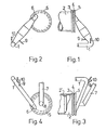
- Figures 1 and 3 are schematic side views and Figures 2 and 4 are corresponding schematic front views showing direct tangential inlets of a suspension inlet duct 1 into a rotatable reaction chamber 2 having an end flange 3 sealed with a seal ring 4 to a stationary end wall 5 equipped with an opening 6 connected with the suspension inlet duct 1.
- a combustion gas outlet duct is situated at the opposite end of the reaction chamber 2.
- a gas outlet duct 7 is situated at the upper end of the reaction chamber 2 communicating with the reaction chamber via an opening 8 in the end wall 5.
- the suspension inlet duct 1 is provided with inlets 9 and 10 for fuel and material, respectively.
- Figures 3 and 4 further show a constriction member 2' provided as a thickening of the lining in the reaction chamber 2.
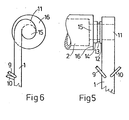
- Figures 5 and 6 show as a schematic side view and a schematic front view, respectively, a suspension inlet with a spiral flow chamber 11 having a flange 12 sealed with a seal ring 13 to a flange 14 on the upper end of the reaction chamber 2, defining an axial suspension inlet opening 15.
- a peripheral part 16 of the end wall of the reaction chamber 2 is fixed to the reaction chamber.
- the suspension inlet duct 1 is provided with inlets 9 and 10 for fuel and material, respectively and tangentially connected to the spiral flow chamber 11.
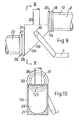
- Figures 7, 9 and 11 are schematic side views showing details of the material outlet end of a reaction chamber 2.
- Figures 8, 10 and 12 are schematic sections taken on the lines VIII-VIII, X-X, and XII-XII, respectively in Figures 7, 9, and 11.
- Figures 7-12 show the lower part of the reaction chamber 2 provided with an inner lining 17 and a flange 18 sealed with a seal ring 19 to a stationary end wall 20 which is mounted to an air outlet 21 of a cooler 22.
- the lower part of the end wall 20 is provided with an opening 23 defining the material outlet of the reaction chamber 2 and the material inlet of the cooler 22.
- the upper part of the end wall 20 is provided with a section opening 24 defining an exhaust gas exit communicating with a gas outlet duct 7 at the lower end of the reaction chamber 2.
- the cooler 22 is a grate cooler with a double air outlet 21, the first for removing excess hot exit air from the cooler, situated at the top of the cooler, and the second being box shaped with sidewalls 124 one of which is provided with an opening 25 communicating with the gas inlet end of the suspension inlet duct 1.
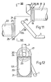
- the cooler 22 is a rotary drum cooler comprising a drum with an end flange 26 which by a seal ring 27 is sealed to a flange 28 on an exit air hood defining the cooler air outlet 21.
- the exit air hood is provided with an inclined bottom plate 29 leading the material from the materal outlet opening 23 to the cooler drum and with sidewalls 124 one of which is provided with an opening 25 communicating with the gas inlet end of the suspension inlet duct 1.
- the top of the exit air hood is provided with a duct 30 for removing excess hot exit air from the cooler 22.
- the area of the material outlet opening 23 is greater than in figures 9 and 10 permitting a part of the exit air from the cooler 22 to pass through the opening 23, quenching the gas at the lower end of the reaction chamber 2 and providing a precooling of the product before it is discharged to the cooler 22.
- the material to be thermally treated is suspended in hot exit air from the cooler 22 in the suspension inlet duct 1.
- the material to be treated is advantageously preheated, e.g. in suspension by exit gas from the reaction chamber.
- Fuel is introduced in the suspension inlet duct above, below or at the same height as the material.
- the gas velocity in the suspension inlet duct 1 is kept at a level so high that the suspended particles and the gas have almost the same velocity.
- the gas is not subjected to violent changes of direction so that the number of collisions between particles and the wall is kept to a minimum.
- the risk of cakings may be further reduced in a known manner by drawings in a gas along the walls of the suspension inlet duct.
- the suspended material is heated to the treating temperature in a few seconds. Then it is introduced into the upper part of the reaction chamber 2 with a tangential velocity component. Due to this velocity component the suspension will perform a rapid helical movement in the upper part of the reaction chamber 2, and the material will be precipitated from the suspension as in an ordinary horizontal cyclone.
- the precipitated material will rotate along the inner surface in an annular material layer, but due to friction the speed of rotation will decrease as the material moves further into the reaction chamber 2 and finally the precipitated material will settle on the bottom of the reaction chamber 2 and form a material layer which will be carried through and subjected to thermal treatment in the reaction chamber with a retention time being determined by the rotational speed of the reaction chamber.
- the material is discharged through the material outlet opening 23 and is introduced into the air cooler 22 where it is cooled countercurrently to cooling air.
- the hot exit air from the cooler 22 or part thereof is introduced into the suspension inlet duct 1, the air flow being provided by means of a fan (not shown) and, if desired, being controlled by means of a valve (not shown) in the air inlet end of the suspension inlet duct 1.
- a certain amount of (false) air may bypass the suspension inlet duct 1 and pass directly from the cooler 22 to the lower end of the reaction chamber 2 via the material outlet opening 23.
- the amount of false air can be kept very low by minimizing the area of the material outlet opening 23.
- a certain amount of false air may be desirable, especially when the gas outlet is arranged at the lower end of the reaction chamber 2, because it provides a quenching of the exit gas from the reaction chamber 2 and a precooling of the thermally treated material.
- the plant shown in figures 13-14 comprises a suspension preheater comprising cyclones 31, 32 and 33, an inlet 34 and an outlet 35 for heating gas, and an inlet 36 and an outlet 37 for pulverous cement raw material; a suspension calciner with a calcination chamber 38 provided with a separating cyclone 39, an inlet 40 for fuel, and an inlet 41 for combustion air and preheated raw material, and an outlet 42 for calcined material from the separating cyclone 39; and a sintering apparatus 43 comprising a reaction chamber 2 rotatable around an axis slightly inclined to the horizontal, a suspension inlet duct 1 provided with inlets 9 and 10 for fuel material, respectively, the inlet duct 1 having a first end connected to an air cooler 22 and a second end connected to the upper end of the reaction chamber 2, the reaction chamber 2 being provided with a gas outlet duct 7 connected to the lower or upper end of the reaction chamber 2 in figures 13, 14 respectively.
- the arrangement at the upper end of the reaction chamber 2 in figure 13 may be shown in figures 1, 2, or figures 5, 6, and at the lower end as shown in figures 7, 8, or 11, 12.
- the rotary drum cooler 22 may be replaced by a grate cooler.
- the arrangement at the upper end of the reaction chamber 2 in figure 14 may be as shown in figures 3, 4, or figures 5, 6 and at the lower end as shown in figure 14 or as shown in figures 9, 10.
- the gas outlet duct 7 may be axially connected to the reaction chamber 2.
- An air cooler 22 for the cooling the sintered material has an air outlet 21 connected to both the inlet duct 1 of the sintering apparatus 43 and the air inlet 41 of the calciner.
- the inlet duct 1 is arranged to introduce material with a tangential component into the reaction chamber 2 as shown in more detail in figures 1-4.
- FIGS 13 and 14 show a grate cooler as cooler 22 which may be provided with a duct (not shown) for excess hot cooling air.
- the grate cooler can be replaced by a rotary drum cooler.
- the method of thermally treating pulverulent material is well suited for sintering material comprising oxides of calcium, silicon, aluminium, and iron, such as calcined cement raw meal to cement clinker.
- the method can also advantageously be used when extracting alumina from low grade alumina bearing ores e.g. by the so-called lime and lime/soda processes where a fine ground mixture of alumina bearing ore and limestone/limestone and alkali metal carbonate, respectively, are calcined and sintered to clinker containing and alumina component in soluble form as calcium aluminate and alkali metal aluminate, respectively, and the impurities in insoluble form, e.g. the Si0 2 component as insoluble dicalcium-silicate.
- the procedure will normally be to introduce and preheat the cold cement raw meal in the suspension preheater, suspending the preheated raw meal in an oxygen containing gas in the calcination chamber 38 with simultaneous addition of fuel.
- the calcined material is then separated from the gas in the separating cyclone 39 and suspended in hot oxygen containing gas, i.e. hot exit air from the clinker cooler 22, in the suspension inlet duct 1.
- the hot calcined material coming from the calciner will have an oxide composition typically within the range CaO: 62-66%, AI z 0 3 : 6-10% Si0 2 : 17-24% and Fe 2 0 3 : 1-6% and a temperature of 800-850°C.
- Fuel such as oil, gas or coal dust is introduced in the hot air flow in the suspension inlet duct 1 before, after, simultaneously with, or together with the hot precalcined cement raw meal.
- the material temperature will be raised to 1350-1450°C, being the sintering temperature of the materials involved.
- the suspended material is then introduced into the reaction chamber 2 as previously described.
- the material In the upper part of the reaction chamber 2 the material is separated from the suspension and the separated agglomerating material is then sintered on its way down towards the material outlet.
- the retention time is controllable by setting the rotational speed of the reaction chamber 2, and will normally be 7-12 minutes.
- the temperature of the discharged cement clinker is typically approximately 1400°C.
- the discharged clinker is then air cooled in the clinker cooler 22.
- Part of the hot cooling air is used as the above mentioned hot air in which the calcined raw meal is suspended in the suspension inlet duct 1.
- the remaining part is passed to the calciner in which it is used as combustion air for the raw meal calcining.
- the hot gas discharged from the reaction chamber 2 typically has a temperature of 1400-1500°C and is introduced through the duct 7 to the bottom of the calcination chamber 38 and is used as a supplementary heat source for calcining the material.
- the exit gas from the calciner is used in known manner for preheating the raw meal to the calcined.
- the gas flow may be introduced into a separator, e.g. a cyclone separator for separating solid material which is passed to the calciner or to the suspension inlet duct when calcined material is introduced.
- a separator e.g. a cyclone separator for separating solid material which is passed to the calciner or to the suspension inlet duct when calcined material is introduced.
- Typical reaction chamber 2 dimensions are diameter 4m., length 12-20 m.
- the rotational speed of the reaction chamber 2 typically 1-4 r.p.m.
- a typical inclination of the reaction chamber will be 3° which is barely preceptible in the accompanying drawings.
- the degree of filling in the reaction chamber is typically 15-20 per cent.
- the production capacity of such a plant is 2000 tons/24 hrs.
Landscapes
- Engineering & Computer Science (AREA)
- Mechanical Engineering (AREA)
- General Engineering & Computer Science (AREA)
- Furnace Details (AREA)
- Muffle Furnaces And Rotary Kilns (AREA)
- Curing Cements, Concrete, And Artificial Stone (AREA)
- Feeding, Discharge, Calcimining, Fusing, And Gas-Generation Devices (AREA)
- Devices And Processes Conducted In The Presence Of Fluids And Solid Particles (AREA)
- Physical Or Chemical Processes And Apparatus (AREA)
Applications Claiming Priority (2)
| Application Number | Priority Date | Filing Date | Title |
|---|---|---|---|
| GB8036836 | 1980-11-17 | ||
| GB8036836 | 1980-11-17 |
Publications (2)
| Publication Number | Publication Date |
|---|---|
| EP0052429A1 EP0052429A1 (en) | 1982-05-26 |
| EP0052429B1 true EP0052429B1 (en) | 1984-07-25 |
Family
ID=10517364
Family Applications (1)
| Application Number | Title | Priority Date | Filing Date |
|---|---|---|---|
| EP19810304899 Expired EP0052429B1 (en) | 1980-11-17 | 1981-10-20 | Method and apparatus for thermally treating pulverulent material |
Country Status (8)
| Country | Link |
|---|---|
| EP (1) | EP0052429B1 (OSRAM) |
| JP (1) | JPS57117332A (OSRAM) |
| KR (1) | KR830008545A (OSRAM) |
| BR (1) | BR8107461A (OSRAM) |
| CA (1) | CA1170043A (OSRAM) |
| DE (1) | DE3165100D1 (OSRAM) |
| DK (1) | DK150270C (OSRAM) |
| IN (1) | IN156235B (OSRAM) |
Families Citing this family (1)
| Publication number | Priority date | Publication date | Assignee | Title |
|---|---|---|---|---|
| DE3237343A1 (de) * | 1982-10-08 | 1984-04-12 | Klöckner-Humboldt-Deutz AG, 5000 Köln | Verfahren und anlage zur waermebehandlung eines vorerhitzten, weitgehend kalzinierten feinkoernigen gutes |
Family Cites Families (6)
| Publication number | Priority date | Publication date | Assignee | Title |
|---|---|---|---|---|
| GB457957A (en) * | 1935-03-11 | 1936-12-09 | Eugene Camille Saint Jacques | Improvements in or relating to furnaces for the treatment of pulverulent materials |
| DE1807292C3 (de) * | 1968-11-06 | 1974-09-05 | Polysius Ag, 4723 Neubeckum | Anlage zum Brennen und/oder Sintern von Feingut |
| DE2120482A1 (de) * | 1971-04-27 | 1972-11-02 | Klöckner-Humboldt-Deutz AG, 5000 Köln | Verfahren und Vorrichtung zur chemischen und/oder physikalischen Behandlung von feinkörnigem Gut |
| GB1446241A (en) * | 1974-03-22 | 1976-08-18 | Smdth Co As F L | Method of and plant for calcinating pulverous raw material |
| FR2279043A1 (fr) * | 1974-07-17 | 1976-02-13 | Fives Cail Babcock | Installation de traitement thermique de matieres pulverulentes notamment pour la fabrication du ciment |
| DE2738987A1 (de) * | 1977-08-30 | 1979-03-15 | Ferdinand Dr Mont Fink | Verfahren und vorrichtung zum brennen von zement |
-
1981
- 1981-10-20 DE DE8181304899T patent/DE3165100D1/de not_active Expired
- 1981-10-20 EP EP19810304899 patent/EP0052429B1/en not_active Expired
- 1981-11-05 DK DK489881A patent/DK150270C/da not_active IP Right Cessation
- 1981-11-13 CA CA000390024A patent/CA1170043A/en not_active Expired
- 1981-11-17 JP JP18432181A patent/JPS57117332A/ja active Pending
- 1981-11-17 BR BR8107461A patent/BR8107461A/pt unknown
- 1981-11-17 IN IN1277/CAL/81A patent/IN156235B/en unknown
- 1981-11-17 KR KR1019810004449A patent/KR830008545A/ko not_active Withdrawn
Also Published As
| Publication number | Publication date |
|---|---|
| DK150270B (da) | 1987-01-26 |
| KR830008545A (ko) | 1983-12-10 |
| JPS57117332A (en) | 1982-07-21 |
| DK150270C (da) | 1987-10-12 |
| DK489881A (da) | 1982-05-18 |
| DE3165100D1 (en) | 1984-08-30 |
| EP0052429A1 (en) | 1982-05-26 |
| BR8107461A (pt) | 1982-08-10 |
| IN156235B (OSRAM) | 1985-06-01 |
| CA1170043A (en) | 1984-07-03 |
Similar Documents
| Publication | Publication Date | Title |
|---|---|---|
| US4381916A (en) | Method and apparatus for roasting fine grained ores | |
| SU1085516A3 (ru) | Установка дл обжига порошкообразного материала | |
| US3584850A (en) | Rotary kiln for shock sintering | |
| US4226586A (en) | Method and apparatus for the thermal treatment of fine-grained material with hot gases | |
| GB2097903A (en) | Production of anhydrous alumina | |
| US3932117A (en) | Method of burning or sintering fine-grain material | |
| CA1161072A (en) | Process of producing cement clinker | |
| KR910000710B1 (ko) | 분말원료 소성장치 | |
| GB2131408A (en) | A method of and apparatus for burning or roasting cement clinker | |
| US4473352A (en) | Double-incline shaft kiln | |
| EP0486535B1 (en) | Heating and treatment of particulate material | |
| EP0052430B1 (en) | Method and apparatus for thermally treating pulverulent material | |
| GB2127946A (en) | A method of and a plant for burning or roasting fine-grained material | |
| US4557688A (en) | Method and apparatus for calcining pulverulent raw material | |
| EP0052429B1 (en) | Method and apparatus for thermally treating pulverulent material | |
| CA1284878C (en) | Method and apparatus for producing dead burnt materials | |
| US3383438A (en) | Calcination of clay | |
| US4420303A (en) | Method and apparatus for thermally treating pulverulent materials | |
| US3964922A (en) | Process for calcination of cement-clinker | |
| US4342598A (en) | Method and apparatus for manufacturing cement clinker | |
| EP0052431B1 (en) | Cement burning plant | |
| US3903612A (en) | Apparatus for preheating solid particulate material | |
| US4416697A (en) | Method for preheating cement clinker raw materials | |
| EP0052925B1 (en) | Method and plant for treating granular or pulverous raw material | |
| CA1276433C (en) | Process of carrying out high-temperature reactions |
Legal Events
| Date | Code | Title | Description |
|---|---|---|---|
| PUAI | Public reference made under article 153(3) epc to a published international application that has entered the european phase |
Free format text: ORIGINAL CODE: 0009012 |
|
| AK | Designated contracting states |
Designated state(s): BE DE FR GB IT LU NL |
|
| 17P | Request for examination filed |
Effective date: 19820813 |
|
| ITF | It: translation for a ep patent filed | ||
| GRAA | (expected) grant |
Free format text: ORIGINAL CODE: 0009210 |
|
| AK | Designated contracting states |
Designated state(s): BE DE FR GB IT LU NL |
|
| REF | Corresponds to: |
Ref document number: 3165100 Country of ref document: DE Date of ref document: 19840830 |
|
| ET | Fr: translation filed | ||
| PGFP | Annual fee paid to national office [announced via postgrant information from national office to epo] |
Ref country code: FR Payment date: 19841026 Year of fee payment: 4 |
|
| PG25 | Lapsed in a contracting state [announced via postgrant information from national office to epo] |
Ref country code: LU Free format text: LAPSE BECAUSE OF NON-PAYMENT OF DUE FEES Effective date: 19841031 |
|
| PGFP | Annual fee paid to national office [announced via postgrant information from national office to epo] |
Ref country code: DE Payment date: 19841102 Year of fee payment: 4 |
|
| PGFP | Annual fee paid to national office [announced via postgrant information from national office to epo] |
Ref country code: BE Payment date: 19841231 Year of fee payment: 4 |
|
| PLBE | No opposition filed within time limit |
Free format text: ORIGINAL CODE: 0009261 |
|
| STAA | Information on the status of an ep patent application or granted ep patent |
Free format text: STATUS: NO OPPOSITION FILED WITHIN TIME LIMIT |
|
| 26N | No opposition filed | ||
| PGFP | Annual fee paid to national office [announced via postgrant information from national office to epo] |
Ref country code: NL Payment date: 19861031 Year of fee payment: 6 |
|
| PG25 | Lapsed in a contracting state [announced via postgrant information from national office to epo] |
Ref country code: BE Effective date: 19871031 |
|
| BERE | Be: lapsed |
Owner name: F.L. SMIDTH & CO. A/S Effective date: 19871031 |
|
| PG25 | Lapsed in a contracting state [announced via postgrant information from national office to epo] |
Ref country code: NL Effective date: 19880501 |
|
| NLV4 | Nl: lapsed or anulled due to non-payment of the annual fee | ||
| PG25 | Lapsed in a contracting state [announced via postgrant information from national office to epo] |
Ref country code: GB Effective date: 19881020 |
|
| PG25 | Lapsed in a contracting state [announced via postgrant information from national office to epo] |
Ref country code: FR Free format text: LAPSE BECAUSE OF NON-PAYMENT OF DUE FEES Effective date: 19890630 |
|
| PG25 | Lapsed in a contracting state [announced via postgrant information from national office to epo] |
Ref country code: DE Effective date: 19890701 |
|
| GBPC | Gb: european patent ceased through non-payment of renewal fee | ||
| REG | Reference to a national code |
Ref country code: FR Ref legal event code: ST |