EP0052391A2 - Vorrichtung zur Fraktionierung einer Lösung durch Elektrophorese - Google Patents
Vorrichtung zur Fraktionierung einer Lösung durch Elektrophorese Download PDFInfo
- Publication number
- EP0052391A2 EP0052391A2 EP81201179A EP81201179A EP0052391A2 EP 0052391 A2 EP0052391 A2 EP 0052391A2 EP 81201179 A EP81201179 A EP 81201179A EP 81201179 A EP81201179 A EP 81201179A EP 0052391 A2 EP0052391 A2 EP 0052391A2
- Authority
- EP
- European Patent Office
- Prior art keywords
- fractionation
- frame
- solution
- membranes
- tongues
- Prior art date
- Legal status (The legal status is an assumption and is not a legal conclusion. Google has not performed a legal analysis and makes no representation as to the accuracy of the status listed.)
- Granted
Links
Images


Classifications
-
- G—PHYSICS
- G01—MEASURING; TESTING
- G01N—INVESTIGATING OR ANALYSING MATERIALS BY DETERMINING THEIR CHEMICAL OR PHYSICAL PROPERTIES
- G01N27/00—Investigating or analysing materials by the use of electric, electrochemical, or magnetic means
- G01N27/26—Investigating or analysing materials by the use of electric, electrochemical, or magnetic means by investigating electrochemical variables; by using electrolysis or electrophoresis
- G01N27/416—Systems
- G01N27/447—Systems using electrophoresis
- G01N27/44756—Apparatus specially adapted therefor
- G01N27/44769—Continuous electrophoresis, i.e. the sample being continuously introduced, e.g. free flow electrophoresis [FFE]
-
- B—PERFORMING OPERATIONS; TRANSPORTING
- B01—PHYSICAL OR CHEMICAL PROCESSES OR APPARATUS IN GENERAL
- B01D—SEPARATION
- B01D57/00—Separation, other than separation of solids, not fully covered by a single other group or subclass, e.g. B03C
- B01D57/02—Separation, other than separation of solids, not fully covered by a single other group or subclass, e.g. B03C by electrophoresis
Definitions
- the invention relates to a device for fractionating a solution in order to separate at least two groups of substances dissolved in it; it targets an electrophoresis fractionation device, using an electric field to produce a migration of substances.
- Electrophoresis has already been used in the laboratory to fractionate a solution and obtain liquid fractions, enriched with substances contained in the initial solution; the main interest of this type of process is that it retains the specific properties of the fractionated substances without denaturing them and also that it leads to low energy consumption.
- the known devices do not make it possible to take full advantage of the advantages that the electrophoresis processes provide (low energy consumption, absence of denaturation of the fractionated substances) due to the inherent defects in each of these devices, which are opposed , to an industrial implementation.
- the present invention proposes to suppri mer the shortcomings of known devices for fractionation by electrophoresis, in order to fully enjoy the benefits of electrophoresis.
- An essential objective of the invention is to considerably improve the efficiency of the devices, so as to achieve high fractionation rates with relatively short operating times, compatible with implementation on an industrial scale.
- Another objective is to provide a device capable of being manufactured at low cost.
- Another objective is to allow fractionation to be carried out continuously.
- Another objective is to extend the possibilities of application of the fractionation processes by. electrophoresis, thanks to the considerable improvement in the efficiency of the devices according to the invention.
- Another objective is to radically eliminate any prior step of dialysis or any other similar type of preparation.
- the electrophoresis fractionation device targeted by the invention is of the type comprising electrodes for generating an electric field and, between them, at least two semi-permeable membranes delimiting at least one fractionation chamber provided with means admission of a solution and means for withdrawing liquid fractions; according to the present invention each fractionation chamber is delimited by a peripheral frame provided with a plurality of tabs joining two sides of said frame and having the same thickness as the latter, the two semi-permeable membranes being applied, on both sides other, against the faces of said frame and against the faces of said tongues so that these membranes are kept separated by a constant distance over their entire surface and that the volume comprised between said membranes is divided by the tongues into a plurality of elongated volumes.
- the structure of the device according to the invention thanks to the perfect guidance of the membranes over their entire surface, makes it possible to very precisely adjust the distance between them (and therefore the thickness of the fractionation chambers), so as to in each case, place yourself in the maximum separation zone.
- guard compartments are arranged between each electrode and the corresponding extreme fractionation chamber; these compartments are associated with food means tation in an auxiliary solution and means of evacuation thereof. They are delimited by a frame provided with tongues similar to those already mentioned, the membrane of the electrode compartment coming to bear against one face of said frame and one face of said tongues, while the membrane of the extreme fractionation chamber comes to bear against the other side of said frame and the other side of said tabs.
- the tongues of said frame are arranged in line with the tongues of the frames of the fractionation chambers, with a view to forming elongated volumes located opposite the corresponding volumes of said chambers.
- the electric field used for fractionation also serves to generate rapid ion exchanges through the membranes between the initial solution contained in the various fractionation chambers and the auxiliary solution contained in the guard compartments.
- This radically eliminates the preliminary preparation operations, in particular dialysis which are necessary in certain conventional devices, as well as all the associated drawbacks; moreover, the initial solution no longer has to be diluted and the process can be applied to natural solutions in the state in which they are produced or collected.
- the method can be applied directly to serum or blood plasma, which eliminates all the manipulations and precautions required by the dilution step.
- the essential characteristics of the initial solution on which the differences in migration between substances depend are constituted by its pH and its salt concentration. Consequently, the concentration and the nature of the ions of the auxiliary solution are chosen in each application so as to carry out ionic exchanges capable of conditioning a suitable pH and saline concentration of the initial solution. This choice depends on the substances present and can be made after preliminary tests with several auxiliary solutions containing different types of ions at different concentrations and at different pH.
- the following ions can be used: phosphate ions (ions of Na 2 HP0 4 3 of KH 2 P0 4 , of K 2 H P0 4 , Na H 2 P0 4 ...), carbonate ions, barbital ions, ions c E- tates etc ...
- the device of the invention allows a continuous implementation of the electrophoresis process, by carrying out a continuous admission of the initial solution and continuous withdrawals of the liquid fractions and by generating a circulation of the auxiliary solution behind the or corresponding semi-permeable membranes, so as to renew said solution continuously in order to preserve a substantially constant ion concentration in said solution.
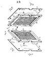
- the device shown by way of example in FIGS. 1 to 7 comprises several fractionation chambers C 1 , C 2 1 C 3 joined together, called to contain the initial solution to be fractionated, two guard compartments G ,, G 2 arranged on the side and on the other, the two extreme chambers called to contain an auxiliary solution, and two compartments of electrode E 1 ,. E 2 arranged on either side of the guard compartments and called to contain an ionic solution.
- Each fractionation chamber C 1 , C2, C3 is delimited on two large faces by two membranes such as 1 and 2 (fig. 2, 3, 4, 5) which are common to the two neighboring chambers and allow it to be separated from them. this.
- each chamber is delimited on its periphery by a frame 3 against which the membranes 1 and 2 are applied sealingly. These frames will be described in detail later.
- each guard compartment G 1 or G 2 is separated, on the one hand, from the neighboring fractionation chamber by a semi-permeable membrane 4 identical to those which separate the chambers, on the other hand from the compartment neighboring electrode by an identical semi-permeable membrane 5; in addition, each guard compartment is delimited on its periphery by a frame 6 against which the membranes 4 and 5 are applied sealingly; these frameworks will be described in detail later.
- Each electrode compartment E 1 or E 2 is delimited on its large faces by the membrane 5 which separates it from the guard compartment and by a side panel 7 comprising on an internal face a conductive coating 8, forming the electrode and connected to an electrical source.
- each electrode compartment is delimited by a frame 9 similar to the frame 6 of the guard compartment (with the exception of supply or withdrawal lights from which it is free).
- the membranes, frames and side panels are rectangular in shape and form a stack guided by rods such as 10 and kept in pressure by plates 11 and 12.
- One of the plates 12 is fixed to a support 13 , while the other 11 is movable and is associated with a conventional manual clamping member 14 which makes it possible to apply pressure between the plates to maintain and seal the stack.
- each fractionation chamber C 1 , C 2 - is formed by two identical panels 15, 16 joined tightly against each other by one of their face 15a, 16b; the semi-permeable membranes 1 and 2 which separate the chamber in question from the two neighboring chambers come under pressure against the other faces of said panels 15b, 16a.
- Each of these panels has a thickness equal to that of half the frame (and therefore equal to half the thickness of the chamber).
- These panels can be made of any dielectric material, neutral vis-à-vis the initial solutions to be treated, for example polymethyl methacrylate.
- Each panel 15 or 16 comprises on a face 15a or 16a a recess 17 or 18 extending along one side of it (for example the upper side in FIG. 3); it comprises on the opposite face 15b or 16b an identical recess 19 or 20 extending along the opposite side (lower side).
- One of these recesses (for example 17) is called to play the role of channel of admission of the initial solution towards the active zone of the room, two other recesses, for example 18 and 19, being called to play the role of channels withdrawal (a recess (20) is in the example unused).
- each frame is each pierced with four corresponding lights such as 21.
- the upper recess of each panel (17 or 18) extends to one of these lights 21 without communication with the other light, while the lower recess (19 or 20) extends to the light located opposite without communication with the other light.
- each semi-permeable membrane is also pierced with four slots such as 22 in correspondence with the slots 21.
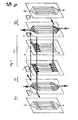
- each of the two panels 15 or 16 forming a frame 3 of the fractionation chamber is provided with parallel tabs, such as 23, which extend vertically from one side to the other of the frame until the recesses of that -this ; these tabs 23 thus divide the volume located between these recesses into a plurality of elongated volumes, which constitute the active zones of the chamber. They make it possible to divide the flow of initial solution into a plurality of parallel threads which extend between the two membranes 1 and 2 of the chamber considered: the admission of the initial solution to said threads as well as the withdrawal of the liquid fractions to from these are carried out in parallel by the channels formed by the top and bottom recesses.
- FIG. 4 is a cross section of a chamber at the level of one of the threads (section through a vertical plane BB perpendicular to the frame), the panels 15 and 16 which constitute each frame, form separating elements 15c and 16c at each liquid stream, along the two sides of the frame.
- a separating element 16c separates the upper intake channel formed by the recess 17 from the upper withdrawal channel formed by the recess 19, while the other separation element 15c delimits the lower withdrawal channel formed by the recess. 18.
- these separation elements 15c, 16c are in the form of a bevel as shown in FIG. 4 and are directed from the sampling zones 18 and 19 towards an intermediate zone Zi of the chamber where the convection speed is very low.
- Figure 4 shows the diagram of the convection speeds inside a liquid stream).
- a divergent diffusion element 15d of structure identical to the separation elements 15c or 16c, is formed by the panel 15 to produce a divergent entry of the initial solution.
- the panels 15 and 16 are identical, the panel 16 carries a similar element 16d on the edge of its recess 20, (which has no role in the example described, since the filling has lcun is achieved through this recess 20) .
- FIG. 6 presents a frame 24 which delimits each guard compartment G 1 and G 2 .
- This frame comprises tongues 25 extending vertically from one side to the other of the latter in line with the tongues 23 of the frames 3 of the fractionation chambers; these tabs 25 thus define elongated volumes opposite the active volumes of the chambers.
- the frame 24 is also pierced with supply means 27 for supplying these volumes in parallel giformes in auxiliary solution and de- evacuation means 26 for evacuating in parallel the auxiliary solution after circulation in said volumes.
- the frame of one of the guard compartments (G 1 ) corresponds and communicates with the supply lights (21, 22) in initial solution of the frames and membranes of the fractionation chambers, in order to allow the 'supply of the inlet channels of said chambers, while the other angled lumen 28 corresponds and communicates with the sampling lumens in order to collect a liquid fraction; for the frame of the other guard compartment (G 2 ) (frame arranged in an inverted position relative to the first), one of these lights corresponds and communicates with the lights for taking the other liquid fraction.
- each electrode compartment E, E 2 is similar to the frame 24 described above with the exception of the lights 28 which are not provided there. It makes it possible to circulate an ionic solution eliminating the products formed in contact with the electrodes and to confine the electric field generated to only the active areas of the fractionation chambers and guard compartments (located between their tongues).
- Examples 1, 2, 3, 4 and 5 which follow are intended to illustrate the possibilities of application of the device of the invention as well as its performance;
- Examples 6 and 7 are intended to illustrate the existence of a maximum of the separation factor when varying the thickness of the splitting chambers without changing any other parameters.
- the supply and withdrawal rates formed below are average rates referred to the unit of useful width for a membrane; they are expressed in cm 3 / hour / cm.
- This liquid fraction was obtained by two successive fractionations carried out in two stages in the device.
- the initial solution for feeding the fragmentation chambers is pure bovine serum of pH between 7.5 and 8 and of composition:
- the operating conditions are as follows:
- the solution originating from the bottom of the cell contains 49% of albumin and 20% of ⁇ -globulins.
- the energy consumed to process one liter of initial solution is equal to 57 Watt-hours.
- the second stage consists of a fractionation of the liquid fraction collected at the bottom of the chambers during stage 1. This fraction of high concentration (202.31 g / l) is diluted 7 times before treatment.
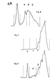
- Table II indicates that the top fraction of the chambers contains only ⁇ and ⁇ -globulins. If for Y-globulins the concentration in this fraction (31.10 g / l) is substantially identical to that of the initial feeding serum (26.35 g / 1), for ⁇ -globulins, the concentration in the fraction from the top (2.70 g / 1) is much lower than in the initial feeding serum (13.91 g / 1). The ⁇ -globulins therefore migrate towards the anode, this migration being able to at least partially justify the loss of biological activity of the top sample (200 ⁇ T ⁇ 250 IU / ml) compared to the initial serum (400 ⁇ T ⁇ 450 IU / ml). Note that gold: recovers 59% of the ⁇ -globulins from the initial solution at the top of the chambers, the ⁇ -globulins thus seeming to migrate slightly towards the cathode.
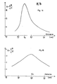
- Figures 8 and 9 present for this example the concentration spectra obtained by analysis on cellulose acetate (IST) respectively for the initial solution (Fig. 8) and for the liquid fraction taken from the top (Fig. 9).
- ⁇ -globulins a low concentration of ⁇ -globulins and traces of albumin (A) (not easy to distinguish on this spectrum).
- Table III which summarizes the results obtained shows that the fraction obtained at the "Top" outlet of the rooms is very much che in ⁇ -globulin (35%) and ⁇ -globulinea (44%).
- the biological activity of this fraction (300 ⁇ T ⁇ 400 IU / ml) is much higher than that measured for the top fraction of Example 1 (200 ⁇ T ⁇ 250 IU / ml). This increase could be due to the relatively high concentration of ⁇ -globulins present in the top fraction (13.83 g / 1 against 13.91 g / 1 in the initial solution). 78% and 52% of the ⁇ -globulins and ⁇ -globulins are respectively recovered from the initial feed solution.
- FIG. 10 shows the concentration spectrum of the top fraction, obtained by analysis on cellulose acetate and illustrates the high concentration of ⁇ -globulins and ⁇ -globulins, with a trace of albumin.
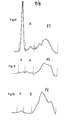
- FIG. 12 shows the concentration spectrum of the high liquid fraction obtained in Example 4 and FIG. 13 the concentration spectrum of the high liquid fraction obtained in Example 5. A slight trace of albumin is observed for both samples analyzed. On the other hand, a high concentration of ⁇ -globulins is noted for the upper fraction of Example 5, a concentration which must certainly be related to the high biological activity of this fraction.
- the curve of FIG. 14 shows that the separation factor (that is to say the ratio of the albumin concentration of the low fraction to the albumin concentration of the high fraction) has a sharp maximum for a distance between membranes. equal to 0.25 cm.
- the optimal conditions can be adjusted by manufacturing frames with a given thickness (in practice within a range of 0.15 to 0.40 cm) and by varying the supply and withdrawal rates until they are in the maximum zone; in the event that these flow rates are imposed by the particular conditions for implementing the application, preliminary tests will be carried out in the laboratory with devices having different frame thicknesses, so as to draw the curve giving the separation factor in depending on this thickness. The final device will be produced by choosing the thickness corresponding to the maximum of this curve.
Landscapes
- Health & Medical Sciences (AREA)
- Life Sciences & Earth Sciences (AREA)
- Chemical & Material Sciences (AREA)
- Molecular Biology (AREA)
- Chemical Kinetics & Catalysis (AREA)
- Electrochemistry (AREA)
- Biochemistry (AREA)
- Analytical Chemistry (AREA)
- Physics & Mathematics (AREA)
- General Health & Medical Sciences (AREA)
- General Physics & Mathematics (AREA)
- Immunology (AREA)
- Pathology (AREA)
- Engineering & Computer Science (AREA)
- Environmental & Geological Engineering (AREA)
- Separation Using Semi-Permeable Membranes (AREA)
- Peptides Or Proteins (AREA)
Priority Applications (1)
| Application Number | Priority Date | Filing Date | Title |
|---|---|---|---|
| AT81201179T ATE8465T1 (de) | 1980-11-07 | 1981-10-26 | Vorrichtung zur fraktionierung einer loesung durch elektrophorese. |
Applications Claiming Priority (2)
| Application Number | Priority Date | Filing Date | Title |
|---|---|---|---|
| FR8023952 | 1980-11-07 | ||
| FR8023952A FR2493725B1 (fr) | 1980-11-07 | 1980-11-07 | Procede et dispositif de fractionnement d'une solution par electrophorese |
Publications (3)
| Publication Number | Publication Date |
|---|---|
| EP0052391A2 true EP0052391A2 (de) | 1982-05-26 |
| EP0052391A3 EP0052391A3 (en) | 1982-06-23 |
| EP0052391B1 EP0052391B1 (de) | 1984-07-18 |
Family
ID=9247848
Family Applications (1)
| Application Number | Title | Priority Date | Filing Date |
|---|---|---|---|
| EP81201179A Expired EP0052391B1 (de) | 1980-11-07 | 1981-10-26 | Vorrichtung zur Fraktionierung einer Lösung durch Elektrophorese |
Country Status (14)
| Country | Link |
|---|---|
| US (1) | US4437967A (de) |
| EP (1) | EP0052391B1 (de) |
| AR (1) | AR224972A1 (de) |
| AT (1) | ATE8465T1 (de) |
| AU (1) | AU543271B2 (de) |
| BR (1) | BR8107229A (de) |
| CA (1) | CA1161789A (de) |
| DE (1) | DE3164907D1 (de) |
| ES (1) | ES507393A0 (de) |
| FR (1) | FR2493725B1 (de) |
| IE (1) | IE52276B1 (de) |
| MX (1) | MX153338A (de) |
| NZ (1) | NZ198902A (de) |
| ZA (1) | ZA817701B (de) |
Cited By (2)
| Publication number | Priority date | Publication date | Assignee | Title |
|---|---|---|---|---|
| FR2568485A1 (fr) * | 1984-08-06 | 1986-02-07 | Rhone Poulenc Rech | Appareil de fractionnement par electrophorese de solutions contenant des proteines, utilisable notamment pour le fractionnement du plasma humain |
| WO2000061607A1 (en) * | 1999-04-12 | 2000-10-19 | Gradipore Limited | Separation of plasma components |
Families Citing this family (4)
| Publication number | Priority date | Publication date | Assignee | Title |
|---|---|---|---|---|
| FR2520235A1 (fr) * | 1982-01-27 | 1983-07-29 | Bel Fromageries | Procede de separation d'immunoglobulines a partir de colostrum |
| US4747929A (en) * | 1986-10-01 | 1988-05-31 | Millipore Corporation | Depletion compartment and spacer construction for electrodeionization apparatus |
| US7097753B2 (en) * | 2002-07-30 | 2006-08-29 | Zhejiang Omex Environmental Engineering Ltd. | Dilute support frame for an EDI device |
| WO2017189680A1 (en) * | 2016-04-26 | 2017-11-02 | Calera Corporation | Intermediate frame, electrochemical systems, and methods |
Family Cites Families (12)
| Publication number | Priority date | Publication date | Assignee | Title |
|---|---|---|---|---|
| CA586187A (en) | 1959-11-03 | V. Arden Thomas | Apparatus for the electrodialytic treatment of liquids | |
| CA750350A (en) | 1967-01-10 | D. Nolan John | Dialytic or electrodialytic cells | |
| DE827350C (de) | 1949-11-03 | 1952-01-10 | Dr Ludwig Kilchling | Geraet zur elektrodialytischen Reinigung von Fluessigkeiten |
| BE534892A (de) * | 1951-09-03 | |||
| US2878178A (en) * | 1955-04-15 | 1959-03-17 | Bier Milan | Continuous free-boundary flow electrophoresis |
| US3079318A (en) * | 1959-01-15 | 1963-02-26 | Bier Milan | Electrical filtering process and device |
| US3359196A (en) | 1959-05-22 | 1967-12-19 | American Mach & Foundry | Electrodialysis device having tapered gasket thickness |
| US3073774A (en) | 1961-08-10 | 1963-01-15 | William J Roberts | Electrodialytic cells |
| US3870617A (en) * | 1971-03-30 | 1975-03-11 | Rhone Poulenc Sa | Apparatus for forced flow electrophoresis |
| US3989613A (en) * | 1973-05-16 | 1976-11-02 | The Dow Chemical Company | Continuous balanced flow fixed boundary electrophoresis |
| GB1462483A (en) | 1974-01-25 | 1977-01-26 | Asahi Glass Co Ltd | Electrodialysis apparatus |
| DE2946284A1 (de) | 1979-11-16 | 1981-05-21 | Forschungsinstitut Berghof GmbH, 7400 Tübingen | Elektrodialyse-zellpaket |
-
1980
- 1980-11-07 FR FR8023952A patent/FR2493725B1/fr not_active Expired
-
1981
- 1981-10-26 AT AT81201179T patent/ATE8465T1/de not_active IP Right Cessation
- 1981-10-26 DE DE8181201179T patent/DE3164907D1/de not_active Expired
- 1981-10-26 EP EP81201179A patent/EP0052391B1/de not_active Expired
- 1981-11-04 CA CA000389378A patent/CA1161789A/fr not_active Expired
- 1981-11-05 ES ES507393A patent/ES507393A0/es active Granted
- 1981-11-06 IE IE2601/81A patent/IE52276B1/en not_active IP Right Cessation
- 1981-11-06 BR BR8107229A patent/BR8107229A/pt not_active IP Right Cessation
- 1981-11-06 ZA ZA817701A patent/ZA817701B/xx unknown
- 1981-11-06 AR AR287367A patent/AR224972A1/es active
- 1981-11-09 US US06/319,408 patent/US4437967A/en not_active Expired - Fee Related
- 1981-11-09 NZ NZ198902A patent/NZ198902A/en unknown
- 1981-11-09 MX MX190012A patent/MX153338A/es unknown
- 1981-11-09 AU AU77194/81A patent/AU543271B2/en not_active Ceased
Cited By (3)
| Publication number | Priority date | Publication date | Assignee | Title |
|---|---|---|---|---|
| FR2568485A1 (fr) * | 1984-08-06 | 1986-02-07 | Rhone Poulenc Rech | Appareil de fractionnement par electrophorese de solutions contenant des proteines, utilisable notamment pour le fractionnement du plasma humain |
| EP0173631A3 (en) * | 1984-08-06 | 1986-03-26 | Rhone-Poulenc Recherches | Apparatus for electrophoretically fractionating protein-containing solutions |
| WO2000061607A1 (en) * | 1999-04-12 | 2000-10-19 | Gradipore Limited | Separation of plasma components |
Also Published As
| Publication number | Publication date |
|---|---|
| EP0052391A3 (en) | 1982-06-23 |
| US4437967A (en) | 1984-03-20 |
| AU7719481A (en) | 1982-07-15 |
| FR2493725A1 (fr) | 1982-05-14 |
| AU543271B2 (en) | 1985-04-18 |
| IE52276B1 (en) | 1987-09-02 |
| ATE8465T1 (de) | 1984-08-15 |
| ZA817701B (en) | 1982-10-27 |
| EP0052391B1 (de) | 1984-07-18 |
| ES8300264A1 (es) | 1982-11-01 |
| DE3164907D1 (en) | 1984-08-23 |
| IE812601L (en) | 1982-05-07 |
| MX153338A (es) | 1986-09-22 |
| BR8107229A (pt) | 1982-07-27 |
| FR2493725B1 (fr) | 1985-12-06 |
| ES507393A0 (es) | 1982-11-01 |
| CA1161789A (fr) | 1984-02-07 |
| AR224972A1 (es) | 1982-01-29 |
| NZ198902A (en) | 1985-12-13 |
Similar Documents
| Publication | Publication Date | Title |
|---|---|---|
| EP0173631B1 (de) | Vorrichtung zur elektrophoretischen Fraktionierung von Proteine enthaltenden Lösungen | |
| EP0187586B1 (de) | Verfahren und Vorrichtungen zur präparativen Elektrophorese | |
| EP0334774B1 (de) | Integrierte Vorrichtung zur biospezifischen Reinigung einer Zellen enthaltenden Flüssigkeit | |
| JP2594786B2 (ja) | 血漿を高分子量の流れを低分子量の流れとに分離する方法 | |
| EP0539280A1 (de) | Verfahren zur wenigstens teilweisen Dehydratisierung von einer wässrigen Zusammensetzung und Vorrichtung zur Durchführung derselben | |
| EP0052391B1 (de) | Vorrichtung zur Fraktionierung einer Lösung durch Elektrophorese | |
| EP0085005B1 (de) | Verfahren zur Trennung von Immunglobulinen aus Kolostrum | |
| JP2008532753A (ja) | 電気濾過方法 | |
| CH622436A5 (de) | ||
| FR2507482A1 (fr) | Procede et dispositif pour le traitement extracorporel du sang | |
| FR2527079A1 (fr) | Procede pour l'obtention, a partir de sang de veau, de substances actives accelerant la respiration cellulaire | |
| US5679231A (en) | Gel bed dialyzer | |
| FR2583300A1 (fr) | Procede et dispositif de separation par electrofiltration de particules solides ou macromolecules, contenues dans une solution | |
| RU92014468A (ru) | Способ получения сверхчистой воды | |
| FR2542620A1 (fr) | Filtre et procede pour l'obtention d'echantillons de plasma sanguin | |
| Bourdeau et al. | Contraluminal serum albumin uptake in isolated perfused renal tubules | |
| JP6146831B2 (ja) | 低分子量成分の除去方法 | |
| CN108993151A (zh) | 一种去除苯丙氨酸发酵液中无机盐的方法 | |
| EP2451825A1 (de) | Verwendung eines co-produkts aus einem verfahren zum auszug von lysozym aus ei-weiss zum erhalten von mindestens einem basischen ei-weissprotein | |
| EP0835610B1 (de) | Entmineralisierung von Milchprodukten oder Milchderivaten | |
| Louisot | Basic Biology of new developments in Biotechnology| A. Hollaender, AI Laskin, P. Rogers, Plenum Press (New York) Editeur, Basic Life Sciences no 25 (1983), p. 579 | |
| Raoul | Biochemical research techniques| John M. Wrigglesworth, A practical introduction, 1 vol., John Wiley and Sons (1983), p. 239 | |
| Selegny et al. | Enrichment and separation of optical isomers by stereoselective active transport in vitro | |
| CH689822A5 (fr) | Purification d'eau par extraction au moyen de membranes liquides mobiles. | |
| JPH01165558A (ja) | アミノ酸化合物の分離方法 |
Legal Events
| Date | Code | Title | Description |
|---|---|---|---|
| PUAI | Public reference made under article 153(3) epc to a published international application that has entered the european phase |
Free format text: ORIGINAL CODE: 0009012 |
|
| PUAL | Search report despatched |
Free format text: ORIGINAL CODE: 0009013 |
|
| AK | Designated contracting states |
Designated state(s): AT BE CH DE FR GB IT LU NL SE |
|
| AK | Designated contracting states |
Designated state(s): AT BE CH DE FR GB IT LU NL SE |
|
| 17P | Request for examination filed |
Effective date: 19820705 |
|
| ITF | It: translation for a ep patent filed | ||
| GRAA | (expected) grant |
Free format text: ORIGINAL CODE: 0009210 |
|
| AK | Designated contracting states |
Designated state(s): AT BE CH DE FR GB IT LI LU NL SE |
|
| REF | Corresponds to: |
Ref document number: 8465 Country of ref document: AT Date of ref document: 19840815 Kind code of ref document: T |
|
| REF | Corresponds to: |
Ref document number: 3164907 Country of ref document: DE Date of ref document: 19840823 |
|
| PLBE | No opposition filed within time limit |
Free format text: ORIGINAL CODE: 0009261 |
|
| STAA | Information on the status of an ep patent application or granted ep patent |
Free format text: STATUS: NO OPPOSITION FILED WITHIN TIME LIMIT |
|
| 26N | No opposition filed | ||
| ITTA | It: last paid annual fee | ||
| PGFP | Annual fee paid to national office [announced via postgrant information from national office to epo] |
Ref country code: LU Payment date: 19931001 Year of fee payment: 13 |
|
| PGFP | Annual fee paid to national office [announced via postgrant information from national office to epo] |
Ref country code: SE Payment date: 19931008 Year of fee payment: 13 |
|
| PGFP | Annual fee paid to national office [announced via postgrant information from national office to epo] |
Ref country code: CH Payment date: 19931018 Year of fee payment: 13 |
|
| PGFP | Annual fee paid to national office [announced via postgrant information from national office to epo] |
Ref country code: GB Payment date: 19931025 Year of fee payment: 13 |
|
| PGFP | Annual fee paid to national office [announced via postgrant information from national office to epo] |
Ref country code: FR Payment date: 19931026 Year of fee payment: 13 |
|
| PGFP | Annual fee paid to national office [announced via postgrant information from national office to epo] |
Ref country code: BE Payment date: 19931028 Year of fee payment: 13 |
|
| PGFP | Annual fee paid to national office [announced via postgrant information from national office to epo] |
Ref country code: AT Payment date: 19931029 Year of fee payment: 13 |
|
| PGFP | Annual fee paid to national office [announced via postgrant information from national office to epo] |
Ref country code: NL Payment date: 19931031 Year of fee payment: 13 |
|
| EPTA | Lu: last paid annual fee | ||
| PGFP | Annual fee paid to national office [announced via postgrant information from national office to epo] |
Ref country code: DE Payment date: 19931228 Year of fee payment: 13 |
|
| PG25 | Lapsed in a contracting state [announced via postgrant information from national office to epo] |
Ref country code: LU Free format text: LAPSE BECAUSE OF NON-PAYMENT OF DUE FEES Effective date: 19941026 Ref country code: GB Effective date: 19941026 Ref country code: AT Effective date: 19941026 |
|
| PG25 | Lapsed in a contracting state [announced via postgrant information from national office to epo] |
Ref country code: SE Effective date: 19941027 |
|
| PG25 | Lapsed in a contracting state [announced via postgrant information from national office to epo] |
Ref country code: LI Effective date: 19941031 Ref country code: CH Effective date: 19941031 Ref country code: BE Effective date: 19941031 |
|
| EAL | Se: european patent in force in sweden |
Ref document number: 81201179.9 |
|
| BERE | Be: lapsed |
Owner name: CENTRE NATIONAL DE LA RECHERCHERCHE SCIENTIFIQUE Effective date: 19941031 |
|
| PG25 | Lapsed in a contracting state [announced via postgrant information from national office to epo] |
Ref country code: NL Effective date: 19950501 |
|
| NLV4 | Nl: lapsed or anulled due to non-payment of the annual fee | ||
| GBPC | Gb: european patent ceased through non-payment of renewal fee |
Effective date: 19941026 |
|
| PG25 | Lapsed in a contracting state [announced via postgrant information from national office to epo] |
Ref country code: FR Effective date: 19950630 |
|
| REG | Reference to a national code |
Ref country code: CH Ref legal event code: PL |
|
| PG25 | Lapsed in a contracting state [announced via postgrant information from national office to epo] |
Ref country code: DE Effective date: 19950701 |
|
| EUG | Se: european patent has lapsed |
Ref document number: 81201179.9 |
|
| REG | Reference to a national code |
Ref country code: FR Ref legal event code: ST |