EP0052389A1 - Spring assembly for cushion or mattress and method and machine for making such assembly - Google Patents
Spring assembly for cushion or mattress and method and machine for making such assembly Download PDFInfo
- Publication number
- EP0052389A1 EP0052389A1 EP81201176A EP81201176A EP0052389A1 EP 0052389 A1 EP0052389 A1 EP 0052389A1 EP 81201176 A EP81201176 A EP 81201176A EP 81201176 A EP81201176 A EP 81201176A EP 0052389 A1 EP0052389 A1 EP 0052389A1
- Authority
- EP
- European Patent Office
- Prior art keywords
- spring
- spring assembly
- sheets
- strip
- mattress
- Prior art date
- Legal status (The legal status is an assumption and is not a legal conclusion. Google has not performed a legal analysis and makes no representation as to the accuracy of the status listed.)
- Ceased
Links
Images


Classifications
-
- A—HUMAN NECESSITIES
- A47—FURNITURE; DOMESTIC ARTICLES OR APPLIANCES; COFFEE MILLS; SPICE MILLS; SUCTION CLEANERS IN GENERAL
- A47C—CHAIRS; SOFAS; BEDS
- A47C27/00—Spring, stuffed or fluid mattresses or cushions specially adapted for chairs, beds or sofas
- A47C27/04—Spring, stuffed or fluid mattresses or cushions specially adapted for chairs, beds or sofas with spring inlays
- A47C27/045—Attachment of spring inlays to coverings; Use of stiffening sheets, lattices or grids in, on, or under spring inlays
- A47C27/0453—Attachment of spring inlays to outer layers
-
- A—HUMAN NECESSITIES
- A47—FURNITURE; DOMESTIC ARTICLES OR APPLIANCES; COFFEE MILLS; SPICE MILLS; SUCTION CLEANERS IN GENERAL
- A47C—CHAIRS; SOFAS; BEDS
- A47C27/00—Spring, stuffed or fluid mattresses or cushions specially adapted for chairs, beds or sofas
- A47C27/04—Spring, stuffed or fluid mattresses or cushions specially adapted for chairs, beds or sofas with spring inlays
- A47C27/06—Spring inlays
- A47C27/063—Spring inlays wrapped or otherwise protected
- A47C27/064—Pocketed springs
-
- B—PERFORMING OPERATIONS; TRANSPORTING
- B68—SADDLERY; UPHOLSTERY
- B68G—METHODS, EQUIPMENT, OR MACHINES FOR USE IN UPHOLSTERING; UPHOLSTERY NOT OTHERWISE PROVIDED FOR
- B68G7/00—Making upholstery
- B68G7/05—Covering or enveloping cores of pads
- B68G7/054—Arrangements of sheathings between spring cores and overlying paddings
Definitions
- the invention relates to spring assemblies for cushions or mattresses as well as cushions or mattresses comprising such assemblies and methods and machines for manufacturing such assemblies.
- Spring assemblies comprising rows of adjacent upright helical springs are widely known.
- Spring assemblies whereby each spring is encased within a fabric bag.
- These bags then possess common vertical seams with the adjacent spring bags.
- encasing each spring in a bag enables to compress the mattress in a substantially noiseless manner since direct friction between adjacent springs in the mattress is prevented.
- Today such spring assemblies are made on the basis of a type of spring bandolier whereby the springs are enclosed in a fabric sleeve which between each successive spring is closed by stitching so that the successive springs are encased within a row of separate bags.
- This spring bandolier is then placed in zig-zag fashion on the bottom surface of the spring assembly to be formed and the successive zig-zag bag rows (or spring bandoliers) are for example connected by means of a system of binding wires which extend substantially parallel to, and halfway between, the upper surface and the bottom surface of the assembly.
- This production method usually requires much manual labour, and, moreover offers the disadvantage that the bags with springs may become deflected locally so that the normal spring action of the assembly is disturbed at these locations. This badly affects the quality of the mattress. Furthermore, this production method enables to make only assemblies in which the spring bags bags are held close together by means of binding wires.
- a part of the spring bags placed in a spring assembly are at their upper sides, respectively their undersides, locally anchored in a flexible and air-permeable anchoring sheet.
- This sheet will preferably comprise a netting which is at least partly embedded in an elastomer material. The sheet at the same time also behaves or functions as a pressure distributor for the mattress or cushion.
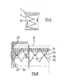
- the spring assembly according to Figure 1 comprises the usual adjacent and upright steel wire springs 1 having a wire diameter of for example 2 mm, a spring diameter of approximately 65 mm, and for example five helical wire coils, and whereby each spring is encased in for example a textile bag 2 which possesses stitched separation seams 3 with the adjacent bags.
- the height of the enclosed springs is approximately 11 cm whereas their height in fully expanded condition is 13 cm.
- the spring coils can have either a cylindrical surface of revolution or e.g. a biconical surface of revolution as shown in figure 6 and wherein the spring coil.30 with the smallest coil diameter is situated substantially halfway between upper and underside of the spring.
- the biconical springs improve the noiseless compression of the assembly because the consecutive coils make less contact with each other upon axial compression than is the case with cylindrical springs.
- the anchoring sheet 4, respectively 5 is fixed to the upper side, respectively the underside of the spring bags.
- the uppersides, respectively the undersides of the textile bags are at least partially pressed into these sheets so that a solid connection is achieved at these places. This embedding is most pronounced in those places where the spring ends (uppermost, respectively bottommost spiral winding) rest against the sheets 4, respectively 5, however without securing the spring end coils themselves in the anchoring sheets.
- the anchoring sheets will preferably be flexible in order to make it possible to follow as well as possible local differences in compression without influencing the compression of adjacent springs (in other words to stimulate the independence of each spring). Hence, an elastomeric sheet must be preferred.
- the anchoring sheets must also be air-permeable in order to allow the spring assembly to breathe. If the anchoring sheets are air tight, they may, for this purpose, be perforated at regular intervals.
- an anchoring sheet with multiple open spaces or composed of independent strips in which a wide-meshed netting 6 is embedded which also forms the connection between the separate strips. It has been found that a polyurethane elastomer layer with a thickness of at least 1 mm, a weight of at least 400 g per m 2 of spring assembly surface and with embedded wide-meshed polypropene yarn netting satisfactorily meets the requirements thereby allowing to omit the fairly rigid conventional pressure distribution layers on spring assemblies (e.g. ca. 1 cm thick needle felt). This results in a lighter cushion or mattress, on the one hand, and more independent spring action, on the other hand.
- spring assemblies e.g. ca. 1 cm thick needle felt
- the anchoring sheet was very strong since cracks or creases or other wear phenomena did not occur after repeated bending.
- the meshes in the netting have preferably a mesh surface between 0,10 cm 2 and 0,50 am 2 whereas the percentage of free mesh surface (empty spaces) is between reap. 50 % and 75 %.
- the elastomeric material can also be applied in narrow strips (width less thanti cm) which are obliquely oriented with respect to the warp and weft threads in the netting. These strips will preferably cross over each other according to a regular pattern to impart a sufficient dimensional stability to the netting.
- a quantity of between 500 g/m 2 and 700 g/m 2 of polyurethane elastomer is suitable as it provides sufficient stability and strength to the netting on the one hand and sufficient anchoring spots with the spring bag rows on the other hand, whereas at the same time the springs and spring bags retain sufficient freedom to exert their spring action as independently as possible from neighbouring springs.
- the sheets 4, 5 can be united on their sides opposite to that of the spring bags with a conventional pressure distributor layer such as a needle fiber felt with a thickness of about 1 cm and a weight of about 1,2 kg/m 2 .
- a conventional pressure distributor layer such as a needle fiber felt with a thickness of about 1 cm and a weight of about 1,2 kg/m 2 .
- an elastomeric anchoring material as e.g. polyurethane offers in itself also a number of advantages compared to the use of adhesives as generally proposed in the past.
- Adhesives applied as layers or strips, often have insufficient tensile strength and resistance against repeated mechanical loading (spring action) so that the dimensional stability thereby suffers. Further they are sensible to ageing and their adhesion capacity can deteriorate under the influence of humidity and/or temperature (heated cushions or mattresses).
- polyurethane rubber offers the advantage that it is completely odourless.
- the spring arrangement in the mattress according to Figure 2 clearly shows the empty intermediate strips 7 between successive zig-zag loops of the spring bandolier near the head end 8 and foot end 9 of the mattress. Due to savings in spring bags in these zones, the mattress can be made lighter and less expensive. This does not have a disadvantageous effect on the quality of the mattress since the greatest weight of a person resting on it is always in the middle of the mattress.
- the invention also permits to compose partial assemblies 10 for mattresses with adapted spring arrangement and density. A number of these partial assemblies can then be combined into a mattress of desired - for example non-standard - dimensions. If, in this way, one wants to make a folding mattress, it is possible to insert in the folding zone 11 a flexible and resilient material strip, for example a foam rubber strip, which can be compressed more easily.
- the partial assemblies will preferably be positioned in such a way that at least one of their edges is embedded in the foam of either strip 11 or the upright mattress contour edge. It is also possible to provide two or more transverse foam strips 11, for example at the level of a folding zone at a distance of a normal cushion from the mattress edge 8 or 9.
- This type of mattresses is able to fold more easily together with the mattress support, the latter being for example a lath grid with raisable head end (e.g. for hospital beds).
- Partial assemblies with suitable dimensions can of course be used as spring cores for cushions, e.g. usable for seating furniture.
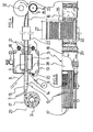
- FIG. 4 A machine for the automatic manufacture of the spring assemblies is schematically shown in Figures 4 and 5.
- spring bandoliers 12 are located in substantially parallel relationship and continuously passed through a coating machine 13 for pressing the undersides 14 respectively the uppersides 15 of these strips into the anchoring sheet 5, respectively 4, and for consolidating the thus coated assembly strip 16.
- the strip 16 can be rolled up which must preferably be done in compressed condition.
- the spring bandoliers 12 can be fed to the coating machine 13 immediately after manufacture or can be unwound from roll packets 17. Indeed, it is possible to roll up the manufactured spring bandoliers in an at least partially compressed condition on a spindle 31 into disc- shaped or cylindrical packets 17 whereby the vertical axes 29 of the compressed spring coils (and separation seams 3) extend in a substantially radial direction in the winding.
- These compressed packets for example in crimp foil packing - take but little space and the thus prepared spring collection can be easily shipped from the spring bandolier manufacturer to the mattress manufacturer.
- These packetsy as an intermediate product for the spring assemblies form in itself an element of the invention also : they can be used for composing either conventional spring assemblies or partial assemblies according to ithe invention.
- the roll packet 17 can be unwound from a pay-off bench and the spring bandoliers 12 can be guided parallel and at suitable common distances between two circulating conveyor belts 18 and 19 while adding the anchoring sheets 4 and 5.
- These sheets may comprise a wide-meshed netting 6 (for example of polypropene yarns).
- An anchoring substance 20 is applied on the conveyor belts 18 and 19 for example by spraying or rackling or rolling, if so desired in strips according to a given pattern. This substance 20 is selected in such a way that after its application on the spring assembly it easily releases from the circulating conveyor belts.
- a polyurethane reaction compound can be applied on the P.V.C.-conveyor belt.
- the upperside 15, respectively the underside 14 contacts the netting 6 and the substance 20 is pressed by means of the conveyor belts through the meshes of the nettings 6 into the surfaces 14 and 15 of the spring bags so that the latter are at least partially pressed into the anchoring substance.
- the distance between the conveyor belts 18 and 19 in this coating zone will be smaller than the height of these spring bags so that the springs are brought under sufficient compressive stress. This stimulates pressing the spring bags into the anchoring substance, particularly near the annular contact area of the uppermost and bottommost spiral windings of each spring.
- the thus coated assembly strip then continues through a consolidation zone, which, for example, may be a tunnel furnace 28 wherein the polymerisation takes place of the polyurethane reaction compound, or the gelling when the anchoring substance 20 comprises a resin that must be cured at high temperature.
- a consolidation zone which, for example, may be a tunnel furnace 28 wherein the polymerisation takes place of the polyurethane reaction compound, or the gelling when the anchoring substance 20 comprises a resin that must be cured at high temperature.
- the conveyor belts leave the assembly strip coated with anchoring sheets 4 and 5, and are eventually cleaned by means of, for example, roller brushes 21 or other cleaning means, while the assembly strip 16, if necessary, will be guided via a cooling tunnel 22 to the winding spool 23 where it is preferably rolled up under radial pressure applied by a counter-pressure roller 24 so that the spring axes extend in a substantially radial direction in the winding.
- This counterpressure roller may for example be equipped with radial projections 25 to prick holes through at
- the distance between the spring bandoliere 12 can be freely adjusted in conformity with the drawing in Figure 2.
- the width of the coating apparatus 13 may therefore be selected in accordance with the length 26 of a mattress, and the assembly strip can be cut transversally each time at a distance equal to the required mattress width 27, either for single or double beds.
- the manufacture of the spring layer can be programmed in such a way that there is an empty bag after each interval equal to the desired mattress width 27.
- the spring bandoliers 42 are then guided synchronously through the coating apparatus 13 so that all empty bags are located in the same transverse row.
- the anchoring sheet at the upperside and underside of the spring assembly also makes that the mattress has a predetermined and constant thickness across its surface.
- a spring assembly not anchored according to the invention indeed generally possesses an uneven surface so that it is necessary to tuft conventional luxury mattresses comprising spring assemblies with loose pressure distributors (and mattresses padding between pressure distributor and mattress cover).
- the constant and controlled distance between facing tuft knots at the underside and upperside of the mattress guarantee a constant mattress thickness.
- the mattress padding between the anchoring sheet and the mattress ticking cover will preferably be so selected that it does not produce noise in case of local compressing (or rubbing) on the anchoring sheet. It has been found that a very porous web of polyacryl fibers (thickness approximately 5 cm) used as an insonorisation layer on a polyurethane anchoring sheet meets this requirement.
- the spring bandolier 12 is delivered from a supply stock, e.g. a wound spring pack 17 and is continuously and crosswise introduced by means of a feeding device according to a zig-zag pattern in the nip 33 between an upper conveyor belt 18 and a lower conveyor belt 19 which constitute together the coating apparatus 13.
- the crests 34 of the zig-zag pattern thereby constitute both longitudinal edges 35 of the spring assembly strip 16.
- the anchoring sheets 4 and 5 are delivered over the conveyor belts 18, 19 and pressed onto the in zig-zag pattern deposited spring rows.
- the apparatus for depositing the spring bandolier 12 in zig-zag pattern comprises a carriage 36 which is moved back and forth over rails 37 in the vicinity of the coating machine 13.
- Two chain conveyors 38 facing each other, are mounted on carriage 36 and they are driven so as to push the bandolier 12 in a connected guiding channel 39 to the nip 33 of the coating machine.
- the chain conveyors 38 are provided at their outsides with ribs 51 which are arranged at a mutual distance so that consecutive spring pockets 2 are catched each time between four synchronously travelling ribs 51.
- Conveyor-belts 42 are also mounted at the upper and underside of channel 42 ; they compress the spring bandolier 12 progressively to e.g. one third of its initial height during its forward movement to the nip 33.
- the driving motor 47 of conveyors 38 and belts 42 is mutually coupled ; it is also adjusted to the driving of carriage 36 by motor 60.
- a protection sleeve 43 is arranged over the exit of channel 39 and belts 42.
- the exit of channel 39 thus moves back and forth in the nip 33 and introduces progressively one cross row in zigzag after the other between sheets 4 and 5 which are supported by the stepwise progressing belts 18 resp. 19.
- the belts 18 and 19 move on one step or increment each time a new zig-zag row is introduced.
- each row shall correspond to the length 26 of the mattress to be made.
- the assembly strip 16 delivered by the coating machine 13 is not wound up, it can be transversely cut between two subsequent zig-zag rows.
- the sheets 4 and 5 are hereby cut and also bandolier 12 at the level of pockets 40 at the crest of the serpentine.
- the process comprising the zig-zag introduction of the bandolier 12 offers the advantage, in comparison to the process described above, that only one or two spring pockets 40 per spring assembly have to be cut and that programming of the synchronous introduction of parallel spring ban - doliers can be deleted.
- Cutting of strip 16 can be carried out in a conventional manner by compressing a transverse zone of strip 16 at both sides of the cutting line 41 (figure 8) to be made and by cutting both the upper and lower anchoring sheet between a horizontally arranged and up and down movable knife and a counterplate. This cutting action can at the same time out up and remove the springs in pockets 40 so as to complete the separation between consecutive spring assemblies.
- the provision of two or even three spring pockets 40 in every transition zone between two consecutive spring assemblies to be separated is useful when it is desired that the anchoring sheets 4 and 5 extend somewhat beyond the spring rows at the periphery of the assembly.
- These extending edges of the anchoring sheets 4 and 5 can then be folded vertically and constitute a reinforcement of the upright edges of the spring assembly. In this way reinforcing the assembly edges by means of a more expensive foaming process can be deleted.
- the coating of netting 6 with obliquely oriented elastomeric strips 54, 55 is e.g. done by pouring the elastomeric reaction compound from pouring nozzles 45 resp. 46 which move transversely back and forth over belts 18 resp. 19. This transverse movement can be linked to the transverse movement of carriage 36.
- the nozzles 45, 46 make further simultaneously an oscillating movement perpendicular to this transverse movement.
- This wave line further on 54 covers a transverse band region comprising and fixing a number of zig-zag spring rows (e.g. four).
- the feeding device for the bandolier 12 further deposits a smaller number of zig-zag rows (e.g. two or three) without pouring action by the nozzles 45, 46.
- a spring row During the next deposition of a spring row the nozzles deposit a next undulated strip 55.
- This method applies when the reaction time of the compound to be laid down is sufficiently slow to allow a periodic stop of pouring without intermediate flushing.
- the pouring apparatus is adjusted such that every wave trough 52 of the preceding line 54 is crossed by a wave crest 53 of the next line 55 as shown in figure 8. These overlapping zones favour the crosswise anchoring of the spring rows in the assembly 16 and the dimensional stability of sheets 4 and 5.
- the oscillation of the pouring nozzles between wave crests and wave troughs is driven and guided by conventional mechanical means 50 mounted in the nozzle carrier 49.
- the shift of the nozzles is guided by the means 50 in the nozzle carriers 49.
- These means 50 will further have to carry out a suitable movement correction of the nozzles when they reverse over the belts 18, 19 in the opposite direction to the effect of depositing a new-kave line which crosses or overlaps the previous line in the right way as illustrated in figure 8.
- This correction will thus comprise a phase shift over half the wave length (£/2) on the one hand and a perpendicular shift in the right sense over a width of two spring rows on the other hand.
- the steering or guiding of the nozzles by means 50 is thus coupled to the driving by motor 58 of the stepwise turning movement of belts 18 and 19 on the one hand and of the back and forward movement of the nozzles across the machine 13 on the other hand and on which movement the driving action for oscillating the nozzle is superposed.
- the transverse movement back and forth over the machine 13 is steered by a conveyor belt 59 running in a rectangular path, driven by motor 44 and to which belt the nozzle carriers 49 are linked while travelling over horizontal rails 56.
- the belt 59 moves back and forth (arrow 57) whereby the nozzles travel in mutual opposite direction from one extreme position (right side of the machine 13) to the other extreme position (left side).
- the rectangular path is preferably of a greater width than the coating machine 13 and so enables the nozzles to move in their extreme positions beyond the side edges 35 of the spring assembly strip 16 and beyond the machine side edges. This enables to flush or rinse the nozzles 45, 46 if needed in their extreme positions above rinsing containers which are arranged at a suitable position at both sides of the coating apparatus 13.
- a spring bandolier 12 as described above, comprising steel wire springs with a spring diameter of 65 mm was delivered from a spring packet 17 comprising approximately 10.500 springs for 25 spring assemblies (single bed mattresses).
- the spring collection was in packet 17 wound under pressure onto a cylindrical spindle 31 with a diameter of 30 cm. This spindle had a length of 1,2 m and end flanges with a diameter of 1 m.
- the packet 17 had a weight of 300 kg.
- the spring bandolier 12 was then delivered with a speed of 30 m/min.
- a spring assembly 16 was in this way delivered at the exit of the machine 13, comprising single bed mattresses with a length of 2 m, a width of 1 m and with each fifteen zig-zag spring rows.
- the anchoring sheets 4, 5 were also introduced in the nip 33.
- a polypropylene yarn netting 6 (type PROMON PP213 - mesh surface about 0,3 cm 2 ) was unwound and combined with a needle felt 48 from cotton fibers needled onto a flexible foam layer with a thickness of 7 mm, which felt 48 had a weight of 1,25 kg/m 2 .
- the needle felt 48 was delivered against belts 18 and 19 and the netting 6 on top thereof.
- a wave strip 54 from elastomeric material was deposited as described above.
- the wave strip had a wave amplitude a of 115 mm and a wave length e of 300 mm.
- the elastomeric material consisted of a polyol diisocyanate reaction compound of the type Elastocoat C6935 TEX (BASF - Elastogran). These elastomeric strips 54, 55 ... partially penetrated the meshes of the netting 6 onto the felt layer 48 so that a mutual connection between both layers was achieved.
- Two zig-zag rows were introduced during the deposition of a wave strip 54 and a new wave strip 55 was laid down at every introduction of a third zig-zag row.
- the amplitude of the wave strip was determined so that every wave strip covered on the average four zig-zag rows and that the crossing distance between wave crests 53 and wave troughs 52 of each pair of consecutive wave strips approximated the width of one spring row.
- the weight of elastomeric material was 550 g/m 2 surface of spring assembly.
- the curing temperature in the oven 28 was about 65°C and the curing time about 8 min.
- the spring assembly strip 16 so covered was subsequently transversely cut to the desired width of single bed mattresses and each mattress comprised about 440 spring bags 2 of which on the average about 40 to 45 % were locally anchored at their undersides 14 resp. their uppersides 15 in sheet 4 resp. 5.
- the spring assembly was subjected to 450.000 compression cycli (150 cycli per minute) as follows. Two flat square plates, each having a side of 35 mm were put on the spring assembly midway between the longitudinal edges of the assembly and in a manner that a transverse assembly edge of 20 cm was left uncovered both at the head end and at the foot end. Both plates were simultaneously and repetitively lowered to a level that the springs were practically completely compressed (total compressed thickness under each plate was about 38 mm). By this action a bulge was created each time in the assembly between the two plates which produced a tensile loading in this central assembly region. The assembly showed no visible damage or wear after this heavy test.
Landscapes
- Engineering & Computer Science (AREA)
- Manufacturing & Machinery (AREA)
- Mechanical Engineering (AREA)
- Mattresses And Other Support Structures For Chairs And Beds (AREA)
Abstract
The invention relates to the automatic production of spring assemblies for cushions or mattresses and for the mattresses and cushions thereby obtained. It also relates to a number of processes and machines for this automatic production and to a spring collection (17) which comprises a spring bandolier (12) wound under radial pressure onto a spindle (31).
According to the invention, spring bandoliers (12), comprising helicoidal springs (1) encased in bags (2), are arranged with a suitable distribution to a strip which is covered at its underside, resp. upperside with a flexible anchoring sheet (5) resp. (4) so as to locally fix a part of the spring bags (2) in the sheets. Preferably the anchoring sheets (4, 5) comprise a wide-meshed netting (6) that is at least partially embedded in an elastomeric material (20). The elastomeric material (20) is thereby deposited on the netting (6) in obliquely arranged strips (54, 55 ...) which cross each other.
Description
- The invention relates to spring assemblies for cushions or mattresses as well as cushions or mattresses comprising such assemblies and methods and machines for manufacturing such assemblies.
- Spring assemblies comprising rows of adjacent upright helical springs are widely known. Currently, for luxury mattresses often spring assemblies are used whereby each spring is encased within a fabric bag. These bags then possess common vertical seams with the adjacent spring bags. Indeed encasing each spring in a bag enables to compress the mattress in a substantially noiseless manner since direct friction between adjacent springs in the mattress is prevented. Today such spring assemblies are made on the basis of a type of spring bandolier whereby the springs are enclosed in a fabric sleeve which between each successive spring is closed by stitching so that the successive springs are encased within a row of separate bags. This spring bandolier is then placed in zig-zag fashion on the bottom surface of the spring assembly to be formed and the successive zig-zag bag rows (or spring bandoliers) are for example connected by means of a system of binding wires which extend substantially parallel to, and halfway between, the upper surface and the bottom surface of the assembly.
- This production method usually requires much manual labour, and, moreover offers the disadvantage that the bags with springs may become deflected locally so that the normal spring action of the assembly is disturbed at these locations. This badly affects the quality of the mattress. Furthermore, this production method enables to make only assemblies in which the spring bags bags are held close together by means of binding wires.
- It is an object of the present invention to obviate these drawbacks and to provide a spring assembly comprising helical springs encased within fabric bags and which can be automatically made at constant quality without local spring disturbances and whereby the position of the spring bags in the assembly can be freely adapted. According to the invention a part of the spring bags placed in a spring assembly are at their upper sides, respectively their undersides, locally anchored in a flexible and air-permeable anchoring sheet. This sheet will preferably comprise a netting which is at least partly embedded in an elastomer material. The sheet at the same time also behaves or functions as a pressure distributor for the mattress or cushion. This and other features and advantages of the anchoring sheet, also with regard to an automatic method of manufacturing the assemblies which thus becomes possible, will now be further clarified by means of a number of embodiments and with reference to the adjoined drawings.
- Figure 1 is a perspective view of a spring assembly with flexible anchoring sheet at the upper and undersides.
- Figure 2 is a plan view of a spring array in the assembly.
- Figure 3 is a view of a composition of a mattress core by means of partial spring assemblies.
- Figure 4 is a schematic side view of a machine or apparatus for the continuous manufacture of spring assemblies.
- Figure 5 is a plan view of the installation according to Figure 4.
- Figure 6 is a view of a biconical spring.
- Figure 7 is a view of an alternative machine for continuous manufacture.
- Figure 8 is a view of a pattern of crossing elastomer strips on the spring assembly.
- The spring assembly according to Figure 1 comprises the usual adjacent and upright steel wire springs 1 having a wire diameter of for example 2 mm, a spring diameter of approximately 65 mm, and for example five helical wire coils, and whereby each spring is encased in for example a
textile bag 2 which possesses stitchedseparation seams 3 with the adjacent bags. The height of the enclosed springs is approximately 11 cm whereas their height in fully expanded condition is 13 cm. The spring coils can have either a cylindrical surface of revolution or e.g. a biconical surface of revolution as shown in figure 6 and wherein the spring coil.30 with the smallest coil diameter is situated substantially halfway between upper and underside of the spring. The biconical springs improve the noiseless compression of the assembly because the consecutive coils make less contact with each other upon axial compression than is the case with cylindrical springs. The anchoring sheet 4, respectively 5 is fixed to the upper side, respectively the underside of the spring bags. The uppersides, respectively the undersides of the textile bags are at least partially pressed into these sheets so that a solid connection is achieved at these places. This embedding is most pronounced in those places where the spring ends (uppermost, respectively bottommost spiral winding) rest against the sheets 4, respectively 5, however without securing the spring end coils themselves in the anchoring sheets. This stimulates keeping the springs in their initial positions in the spring assembly with the result that the mattress or mattress assembly may be repeatedly bent without that the rows of bags and springs tend to deflect, even when there are empty intermediate spaces between adjacent rows of springs. This is an important advantage of the invention, since it makes it possible to determine the array and number of spring bags per m2 in the assembly as desired. - The anchoring sheets will preferably be flexible in order to make it possible to follow as well as possible local differences in compression without influencing the compression of adjacent springs (in other words to stimulate the independence of each spring). Hence, an elastomeric sheet must be preferred. The anchoring sheets must also be air-permeable in order to allow the spring assembly to breathe. If the anchoring sheets are air tight, they may, for this purpose, be perforated at regular intervals.
- However, it is also possible to use an anchoring sheet with multiple open spaces or composed of independent strips in which a wide-meshed
netting 6 is embedded which also forms the connection between the separate strips. It has been found that a polyurethane elastomer layer with a thickness of at least 1 mm, a weight of at least 400 g per m2 of spring assembly surface and with embedded wide-meshed polypropene yarn netting satisfactorily meets the requirements thereby allowing to omit the fairly rigid conventional pressure distribution layers on spring assemblies (e.g. ca. 1 cm thick needle felt). This results in a lighter cushion or mattress, on the one hand, and more independent spring action, on the other hand. Moreover, the anchoring sheet was very strong since cracks or creases or other wear phenomena did not occur after repeated bending. The meshes in the netting have preferably a mesh surface between 0,10 cm 2 and 0,50 am2 whereas the percentage of free mesh surface (empty spaces) is between reap. 50 % and 75 %. - The elastomeric material can also be applied in narrow strips (width less thanti cm) which are obliquely oriented with respect to the warp and weft threads in the netting. These strips will preferably cross over each other according to a regular pattern to impart a sufficient dimensional stability to the netting. A quantity of between 500 g/m2 and 700 g/m2 of polyurethane elastomer is suitable as it provides sufficient stability and strength to the netting on the one hand and sufficient anchoring spots with the spring bag rows on the other hand, whereas at the same time the springs and spring bags retain sufficient freedom to exert their spring action as independently as possible from neighbouring springs. Moreover, the dimensional stability of the sheet does not just improve its favourable behaviour as pressure distributor layer, but it is also necessary for the easy and reliable fixing treatment of the spring assembly edges in foam afterwards. According to another embodiment, the
sheets 4, 5 can be united on their sides opposite to that of the spring bags with a conventional pressure distributor layer such as a needle fiber felt with a thickness of about 1 cm and a weight of about 1,2 kg/m2. This offers the advantage that the thus covered spring assembly ressembles more the conventional spring assemblies to be fixed in foam. The fiber felt is then anchored in the obliquely oriented polyurethane strips and hencesheet 4, 5 serves as a flexible and dimensionally stable supporting layer for the conventional pressure distributor. An effect thereof is that the conventional pressure distributor no longer shifts or excessively and irreparably deforms (creases, extends) locally e.g. during winding up or folding of the assembly or in the mattress areas which are most loaded on the average. - The use of an elastomeric anchoring material as e.g. polyurethane offers in itself also a number of advantages compared to the use of adhesives as generally proposed in the past. Adhesives, applied as layers or strips, often have insufficient tensile strength and resistance against repeated mechanical loading (spring action) so that the dimensional stability thereby suffers. Further they are sensible to ageing and their adhesion capacity can deteriorate under the influence of humidity and/or temperature (heated cushions or mattresses). Finally polyurethane rubber offers the advantage that it is completely odourless.
- The spring arrangement in the mattress according to Figure 2 clearly shows the empty
intermediate strips 7 between successive zig-zag loops of the spring bandolier near the head end 8 andfoot end 9 of the mattress. Due to savings in spring bags in these zones, the mattress can be made lighter and less expensive. This does not have a disadvantageous effect on the quality of the mattress since the greatest weight of a person resting on it is always in the middle of the mattress. - As shown in Figure 3, the invention also permits to compose
partial assemblies 10 for mattresses with adapted spring arrangement and density. A number of these partial assemblies can then be combined into a mattress of desired - for example non-standard - dimensions. If, in this way, one wants to make a folding mattress, it is possible to insert in the folding zone 11 a flexible and resilient material strip, for example a foam rubber strip, which can be compressed more easily. The partial assemblies will preferably be positioned in such a way that at least one of their edges is embedded in the foam of eitherstrip 11 or the upright mattress contour edge. It is also possible to provide two or moretransverse foam strips 11, for example at the level of a folding zone at a distance of a normal cushion from themattress edge 8 or 9. This type of mattresses is able to fold more easily together with the mattress support, the latter being for example a lath grid with raisable head end (e.g. for hospital beds). Partial assemblies with suitable dimensions can of course be used as spring cores for cushions, e.g. usable for seating furniture. - A machine for the automatic manufacture of the spring assemblies is schematically shown in Figures 4 and 5. Hereby,
spring bandoliers 12 are located in substantially parallel relationship and continuously passed through acoating machine 13 for pressing theundersides 14 respectively theuppersides 15 of these strips into theanchoring sheet 5, respectively 4, and for consolidating the thus coated assembly strip 16. If desired, the strip 16 can be rolled up which must preferably be done in compressed condition. - The spring bandoliers 12 can be fed to the
coating machine 13 immediately after manufacture or can be unwound fromroll packets 17. Indeed, it is possible to roll up the manufactured spring bandoliers in an at least partially compressed condition on a spindle 31 into disc- shaped orcylindrical packets 17 whereby thevertical axes 29 of the compressed spring coils (and separation seams 3) extend in a substantially radial direction in the winding. These compressed packets, for example in crimp foil packing - take but little space and the thus prepared spring collection can be easily shipped from the spring bandolier manufacturer to the mattress manufacturer. These packetsy as an intermediate product for the spring assemblies, form in itself an element of the invention also : they can be used for composing either conventional spring assemblies or partial assemblies according to ithe invention. - If an automatic manufacturing method according to the invention is applied, then the
roll packet 17 can be unwound from a pay-off bench and thespring bandoliers 12 can be guided parallel and at suitable common distances between two circulatingconveyor belts anchoring sheets 4 and 5. These sheets may comprise a wide-meshed netting 6 (for example of polypropene yarns). An anchoringsubstance 20 is applied on theconveyor belts substance 20 is selected in such a way that after its application on the spring assembly it easily releases from the circulating conveyor belts. As an example of such a combination, a polyurethane reaction compound can be applied on the P.V.C.-conveyor belt. At the entrance of thecoating apparatus 13 theupperside 15, respectively theunderside 14, contacts thenetting 6 and thesubstance 20 is pressed by means of the conveyor belts through the meshes of thenettings 6 into thesurfaces conveyor belts - The thus coated assembly strip then continues through a consolidation zone, which, for example, may be a
tunnel furnace 28 wherein the polymerisation takes place of the polyurethane reaction compound, or the gelling when the anchoringsubstance 20 comprises a resin that must be cured at high temperature. Next, the conveyor belts leave the assembly strip coated with anchoringsheets 4 and 5, and are eventually cleaned by means of, for example, roller brushes 21 or other cleaning means, while the assembly strip 16, if necessary, will be guided via a coolingtunnel 22 to the winding spool 23 where it is preferably rolled up under radial pressure applied by a counter-pressure roller 24 so that the spring axes extend in a substantially radial direction in the winding. This counterpressure roller may for example be equipped with radial projections 25 to prick holes through at least one anchoring layer when the latter would comprise a full layer. The wound-up assembly strip can be delivered as such to the mattress manufacturer who can then cut them to size. - As shown in Figure 5 the distance between the
spring bandoliere 12 can be freely adjusted in conformity with the drawing in Figure 2. The width of thecoating apparatus 13 may therefore be selected in accordance with thelength 26 of a mattress, and the assembly strip can be cut transversally each time at a distance equal to the requiredmattress width 27, either for single or double beds. In order not to loose a spring row when cutting the strip 16 transversally, the manufacture of the spring layer can be programmed in such a way that there is an empty bag after each interval equal to the desiredmattress width 27. The spring bandoliers 42 are then guided synchronously through thecoating apparatus 13 so that all empty bags are located in the same transverse row. - The anchoring sheet at the upperside and underside of the spring assembly also makes that the mattress has a predetermined and constant thickness across its surface. A spring assembly not anchored according to the invention indeed generally possesses an uneven surface so that it is necessary to tuft conventional luxury mattresses comprising spring assemblies with loose pressure distributors (and mattresses padding between pressure distributor and mattress cover). The constant and controlled distance between facing tuft knots at the underside and upperside of the mattress guarantee a constant mattress thickness. By the application of the invention this tufting operation throughout the full thickness of the mattress can be omitted, which is an additional advantage.
- The mattress padding between the anchoring sheet and the mattress ticking cover will preferably be so selected that it does not produce noise in case of local compressing (or rubbing) on the anchoring sheet. It has been found that a very porous web of polyacryl fibers (thickness approximately 5 cm) used as an insonorisation layer on a polyurethane anchoring sheet meets this requirement.
- In another method of making the spring assembly, it is possible to take only one
spring bandolier 12 and to deposit it continuously in a zig-zag or serpentine pattern on an undermost conveyor belt while joining a continuously deliveredflexible anchoring sheet 5 as described above. At the same time or somewhat further in the processing line, a similar anchoring sheet 4 can be applied and pressed on the serpentine. An apparatus to carry out this method is shown in figure 7 and its structure and operation will be clarified below. - The
spring bandolier 12 is delivered from a supply stock, e.g. awound spring pack 17 and is continuously and crosswise introduced by means of a feeding device according to a zig-zag pattern in thenip 33 between anupper conveyor belt 18 and alower conveyor belt 19 which constitute together thecoating apparatus 13. Thecrests 34 of the zig-zag pattern thereby constitute bothlongitudinal edges 35 of the spring assembly strip 16. At the same time theanchoring sheets 4 and 5 are delivered over theconveyor belts spring bandolier 12 in zig-zag pattern comprises acarriage 36 which is moved back and forth overrails 37 in the vicinity of thecoating machine 13. Twochain conveyors 38, facing each other, are mounted oncarriage 36 and they are driven so as to push thebandolier 12 in a connected guidingchannel 39 to the nip 33 of the coating machine. The chain conveyors 38 are provided at their outsides withribs 51 which are arranged at a mutual distance so that consecutive spring pockets 2 are catched each time between four synchronously travellingribs 51. Conveyor-belts 42 are also mounted at the upper and underside ofchannel 42 ; they compress thespring bandolier 12 progressively to e.g. one third of its initial height during its forward movement to thenip 33. The drivingmotor 47 ofconveyors 38 andbelts 42 is mutually coupled ; it is also adjusted to the driving ofcarriage 36 bymotor 60. Aprotection sleeve 43 is arranged over the exit ofchannel 39 andbelts 42. The exit ofchannel 39 thus moves back and forth in thenip 33 and introduces progressively one cross row in zigzag after the other betweensheets 4 and 5 which are supported by the stepwise progressingbelts 18 resp. 19. Thebelts - Subsequently the travelling direction of
carriage 36 andchannel 39 reverses and a new zig-zag row is introduced. As mentioned above the length of each row shall correspond to thelength 26 of the mattress to be made. When the assembly strip 16, delivered by thecoating machine 13, is not wound up, it can be transversely cut between two subsequent zig-zag rows. Thesheets 4 and 5 are hereby cut and also bandolier 12 at the level ofpockets 40 at the crest of the serpentine. The process comprising the zig-zag introduction of thebandolier 12 offers the advantage, in comparison to the process described above, that only one or twospring pockets 40 per spring assembly have to be cut and that programming of the synchronous introduction of parallel spring ban- doliers can be deleted. - Cutting of strip 16 can be carried out in a conventional manner by compressing a transverse zone of strip 16 at both sides of the cutting line 41 (figure 8) to be made and by cutting both the upper and lower anchoring sheet between a horizontally arranged and up and down movable knife and a counterplate. This cutting action can at the same time out up and remove the springs in
pockets 40 so as to complete the separation between consecutive spring assemblies. The provision of two or even threespring pockets 40 in every transition zone between two consecutive spring assemblies to be separated is useful when it is desired that theanchoring sheets 4 and 5 extend somewhat beyond the spring rows at the periphery of the assembly. These extending edges of theanchoring sheets 4 and 5 can then be folded vertically and constitute a reinforcement of the upright edges of the spring assembly. In this way reinforcing the assembly edges by means of a more expensive foaming process can be deleted. - The coating of netting 6 with obliquely oriented elastomeric strips 54, 55 (figure 8) is e.g. done by pouring the elastomeric reaction compound from pouring
nozzles 45 resp. 46 which move transversely back and forth overbelts 18 resp. 19. This transverse movement can be linked to the transverse movement ofcarriage 36. Thenozzles netting 6. This wave line further on 54 covers a transverse band region comprising and fixing a number of zig-zag spring rows (e.g. four). The feeding device for thebandolier 12 further deposits a smaller number of zig-zag rows (e.g. two or three) without pouring action by thenozzles wave trough 52 of the preceding line 54 is crossed by awave crest 53 of the next line 55 as shown in figure 8. These overlapping zones favour the crosswise anchoring of the spring rows in the assembly 16 and the dimensional stability ofsheets 4 and 5. The oscillation of the pouring nozzles between wave crests and wave troughs is driven and guided by conventional mechanical means 50 mounted in thenozzle carrier 49. - When the reaction time of the compound to be used does not allow a periodic shut off of the pouring action and thus the pouring nozzles have to work continuously, then the transverse movement of
nozzles belts carriage 36. Assuming that this movement is twice as slow, then thebelts belts machine 13 the nozzles will have to shift once vertically over a width of one spring row during their movement across the machine width each time a second zig-zag row is introduced. The shift of the nozzles is guided by themeans 50 in thenozzle carriers 49. These means 50 will further have to carry out a suitable movement correction of the nozzles when they reverse over thebelts means 50 is thus coupled to the driving bymotor 58 of the stepwise turning movement ofbelts machine 13 on the other hand and on which movement the driving action for oscillating the nozzle is superposed. The transverse movement back and forth over themachine 13 is steered by aconveyor belt 59 running in a rectangular path, driven by motor 44 and to which belt thenozzle carriers 49 are linked while travelling overhorizontal rails 56. Thebelt 59 moves back and forth (arrow 57) whereby the nozzles travel in mutual opposite direction from one extreme position (right side of the machine 13) to the other extreme position (left side). The rectangular path is preferably of a greater width than thecoating machine 13 and so enables the nozzles to move in their extreme positions beyond the side edges 35 of the spring assembly strip 16 and beyond the machine side edges. This enables to flush or rinse thenozzles coating apparatus 13. - A
spring bandolier 12 as described above, comprising steel wire springs with a spring diameter of 65 mm was delivered from aspring packet 17 comprising approximately 10.500 springs for 25 spring assemblies (single bed mattresses). The spring collection was inpacket 17 wound under pressure onto a cylindrical spindle 31 with a diameter of 30 cm. This spindle had a length of 1,2 m and end flanges with a diameter of 1 m. Thepacket 17 had a weight of 300 kg. Thespring bandolier 12 was then delivered with a speed of 30 m/min. via a stock accumulation (loosely arranged bandolier length of about 2.000 springs) betweenconveyors 38 and subsequently axially somewhat compressed betweenbelts 42 and delivered through thechannel 39 towards nip 33 in zig-zag line. A spring assembly 16 was in this way delivered at the exit of themachine 13, comprising single bed mattresses with a length of 2 m, a width of 1 m and with each fifteen zig-zag spring rows. Theanchoring sheets 4, 5 were also introduced in thenip 33. For this purpose a polypropylene yarn netting 6 (type PROMON PP213 - mesh surface about 0,3 cm2) was unwound and combined with a needle felt 48 from cotton fibers needled onto a flexible foam layer with a thickness of 7 mm, which felt 48 had a weight of 1,25 kg/m2. The needle felt 48 was delivered againstbelts nozzles netting 6 onto the feltlayer 48 so that a mutual connection between both layers was achieved. Two zig-zag rows were introduced during the deposition of a wave strip 54 and a new wave strip 55 was laid down at every introduction of a third zig-zag row. The amplitude of the wave strip was determined so that every wave strip covered on the average four zig-zag rows and that the crossing distance between wave crests 53 andwave troughs 52 of each pair of consecutive wave strips approximated the width of one spring row. The weight of elastomeric material was 550 g/m2 surface of spring assembly. The curing temperature in theoven 28 was about 65°C and the curing time about 8 min. - The spring assembly strip 16 so covered was subsequently transversely cut to the desired width of single bed mattresses and each mattress comprised about 440
spring bags 2 of which on the average about 40 to 45 % were locally anchored at theirundersides 14 resp. theiruppersides 15 in sheet 4 resp. 5. The spring assembly was subjected to 450.000 compression cycli (150 cycli per minute) as follows. Two flat square plates, each having a side of 35 mm were put on the spring assembly midway between the longitudinal edges of the assembly and in a manner that a transverse assembly edge of 20 cm was left uncovered both at the head end and at the foot end. Both plates were simultaneously and repetitively lowered to a level that the springs were practically completely compressed (total compressed thickness under each plate was about 38 mm). By this action a bulge was created each time in the assembly between the two plates which produced a tensile loading in this central assembly region. The assembly showed no visible damage or wear after this heavy test. - Although the invention has been described with reference to some preferred embodiments, it is not considered to be limited thereto. For the manufacture of spring assemblies for cushions for instance, springs will be used which are compressed to a higher degree in spring bags with a height of about 8 cm. This and other variants of the invention are thus considered to be covered by the claims below.
Claims (24)
1. A spring assembly for a mattress or cushion comprising adjacent, upright helical springs (1) whereby each spring (1) is encased within a bag (2) and whereby each bag (2) possesses a common vertical seam (3) with each adjacent spring bag, characterized in that the uppersides and/or the undersides, of a part of the spring bags (2) are locally anchored in a flexible anchoring sheet (4), respectively (5).
2. A spring assembly according to claim 1, characterized in that the anchoring sheets (4, 5) comprise a netting (6) which is at least partially embedded in an elastomeric material (20).
3. A spring assembly according to claim 2, characterized in that the meshes of the netting (6) have a surface between 0,10 cm2 and 0,50 cm2 whereas the percentage of the free mesh surface in the netting (6) is between respectively 50 % and 75 %.
4. A spring assembly according to any of the previous claims characterized in that the quantity of elastomeric material (20) per m 2 of the netting (6) is between 400 g and 700 g.
5. A spring assembly according to claims 2, 3 or 4, characterized in that the elastomeric material (20) is arranged in strips (54, 55) crossing each other over sheets (4, 5) and which are obliquely oriented with respect to the weft and warp threads of the netting (6).
6. A spring assembly according to any of the previous claims, characterized in that the number of undersides (15) resp. uppersides (15) of the spring bags (2) which are locally anchored in sheet (4) resp. (5) is smaller than 50 % of the total number of spring bags (2) in the spring assembly.
7. A spring assembly according to any of the previous claims, characterized in that the sheets (4, 5) are additionally united with a fiber felt (48) by means of the elastomeric material (20) and on their sides opposite to that of the spring bags (2).
8. A spring assembly according to any of the previous claims, characterized in that the helical springs (1) have a biconical surface of revolution whereby the spring coil (30) with the smallest coil diameter is situated substantially halfway between upper and underside of the spring (1).
9. A mattress or cushion compirising a spring assembly according to any of the previous claims.
10. A mattress or cushion according to claim 9, characterized in that the anchoring sheets (4, 5) are covered with an insonorisation layer.
11. A mattress according to claim 9 or 10, characterized in that it comprises partial assemblies (10) with adapted spring density.
12. A mattress, in particular a foldable mattress according to claim 11, characterized in that flexible and resilient material strips are inserted in the folding area (11).
13. A spring assembly strip (16) comprising at least one spring assembly according to any of the previous claims 1 through 8, characterized in that the strip (16) is wound on a cylindrical spindle (32), with the springs (1) at least partially compressed, and whereby the spring axes (29) extend in a substantially radial direction in the winding.
14. A spring collection (17), characterized in that it comprises a spring bandolier (12) wound on a cylindrical spindle (31), in which bandolier (12) the consecutive springs (1), encased in bags (2), are in an at least partially compressed condition whereby the spring axes (29) extend in a substantially radial direction in the winding.
15. A process for the continuous manufacture of a spring assembly strip (16), characterized in that a number of adjacent spring bandoliers (12) are guided in a substantially parallel relationship through a coating machine (13) for pressing the undersides (14) resp. uppersides (15) of these bandoliers (12) into the anchoring sheets (4) resp. (5), after which the anchoring sheets (4, 5) are consolidated with the spring bandoliers.
16. A process for the continuous manufacture of a spring assembly strip (16), characterized in that one spring bandolier (12) is arranged in a zig-zag pattern and guided through a coating machine (13) whereby the crests (34) of the zig-zag line constitute the longitudinal edges (35) of the assembly strip (16).
17. A process according to claims 15 or 16, characterized in that the coated and consolidated spring assembly strip (16) is tightly wound on a cylindrical spindle (32) while radial pressure is exerted on the strip (16) in the winding zone.
18. A process according to claim 15 or 16, characterized in that a continuous coating layer is applied which, at the exit of the coating machine (13) is perforated at regular intervals.
19. A process according to claim 18, characterized in that the perforation is carried out by means of needles (25) radially projecting on the surface of the counterpressure roller (24) for winding up the spring assembly strip (16).
20. A process according to claim 16, characterized in that the assembly strip (16) is transversally cut at desired distances between two consecutive zig-zag lines at the level of the crest1(40).
21. A process according to any of the previous claims, characterized in that the bandolier or bando-. liers (12) to be introduced are delivered from a spring collection (17) according to claim 14.
22. An apparatus for carrying out the process according to claim 15 characterized in that it comprises means for the parallel and synchronous feeding of a number of spring bandoliers (12) in a coating machine (13), means for covering sheets (6) with elastomeric material (20) and conveyor belts (18, 19) for pressing the covered sheets (6) against and consolidating them with bandoliers (12).
23. An apparatus for carrying out the process according to claim 16, characterized in that it comprises transporting means (36, 38, 39, 42) for the continuous delivery of a spring bandolier (12) in a zigzag in a coating apparatus (13) ; nozzles (45, 46) for applying elastomeric strip (54, 55 ...) in a desired pattern on sheets (48, 6) and conveyor belts (18, 19) for uniting the thus covered sheets with the in zig-zag line shaped spring bandolier (12).
24. An apparatus according to claims 21 or 22 characterized in that it comprises additional means (23) for winding the spring assembly strip (16) and means (24) for radially compressing the same during winding.
Applications Claiming Priority (2)
| Application Number | Priority Date | Filing Date | Title |
|---|---|---|---|
| BE1010041 | 1980-11-19 | ||
| BE1/10041A BE886243A (en) | 1980-11-19 | 1980-11-19 | SPRING CARCASE FOR MATTRESS |
Publications (1)
| Publication Number | Publication Date |
|---|---|
| EP0052389A1 true EP0052389A1 (en) | 1982-05-26 |
Family
ID=3862916
Family Applications (1)
| Application Number | Title | Priority Date | Filing Date |
|---|---|---|---|
| EP81201176A Ceased EP0052389A1 (en) | 1980-11-19 | 1981-10-23 | Spring assembly for cushion or mattress and method and machine for making such assembly |
Country Status (2)
| Country | Link |
|---|---|
| EP (1) | EP0052389A1 (en) |
| BE (1) | BE886243A (en) |
Cited By (12)
| Publication number | Priority date | Publication date | Assignee | Title |
|---|---|---|---|---|
| WO1996011163A1 (en) * | 1994-10-06 | 1996-04-18 | Recticel N.V. | Device for producing a box-spring core |
| WO1997037928A1 (en) * | 1996-04-11 | 1997-10-16 | Slumberland Plc | Spring units for mattresses and the like |
| WO1997045041A1 (en) * | 1996-05-29 | 1997-12-04 | Jansson, Ulf | Bed base |
| ES2140304A1 (en) * | 1997-05-28 | 2000-02-16 | Betere Fab Lucia Antonio | Process for manufacturing spring casings, especially for upholstered elements |
| WO2001056430A1 (en) * | 2000-02-02 | 2001-08-09 | Annova Pty Ltd | Permeable mattress |
| EP1707081A1 (en) * | 2005-03-25 | 2006-10-04 | Compagnie Financiere Europenne de literie | Pocketed spring mattress |
| CN101343032B (en) * | 2007-07-10 | 2011-05-18 | 际诺思(厦门)轻工制品有限公司 | Method for producing spring mattress |
| US8136187B2 (en) | 2007-02-07 | 2012-03-20 | L&P Property Management Company | Slow acting pocketed spring core and method of manufacturing same |
| US8266745B2 (en) | 2007-02-07 | 2012-09-18 | L&P Property Management Company | Slow acting pocketed spring core having fill material inside pockets |
| US8474078B2 (en) | 2007-02-07 | 2013-07-02 | L&P Property Management Company | Slow acting pocketed spring core having cushioning material |
| GB2565197A (en) * | 2017-05-31 | 2019-02-06 | Hs Products Ltd | Pocketed spring unit and method of manufacture |
| CN111278329A (en) * | 2017-10-31 | 2020-06-12 | 丝涟科技有限责任公司 | Pocketed coil spring assembly comprising flexible foam |
Citations (2)
| Publication number | Priority date | Publication date | Assignee | Title |
|---|---|---|---|---|
| US2862214A (en) * | 1956-10-04 | 1958-12-02 | Marspring Corp | Cushion or mattress construction and method of manufacture |
| GB1006735A (en) * | 1962-12-21 | 1965-10-06 | Wood Conversion Co | Spring cushion structure |
-
1980
- 1980-11-19 BE BE1/10041A patent/BE886243A/en not_active IP Right Cessation
-
1981
- 1981-10-23 EP EP81201176A patent/EP0052389A1/en not_active Ceased
Patent Citations (2)
| Publication number | Priority date | Publication date | Assignee | Title |
|---|---|---|---|---|
| US2862214A (en) * | 1956-10-04 | 1958-12-02 | Marspring Corp | Cushion or mattress construction and method of manufacture |
| GB1006735A (en) * | 1962-12-21 | 1965-10-06 | Wood Conversion Co | Spring cushion structure |
Cited By (20)
| Publication number | Priority date | Publication date | Assignee | Title |
|---|---|---|---|---|
| WO1996011163A1 (en) * | 1994-10-06 | 1996-04-18 | Recticel N.V. | Device for producing a box-spring core |
| WO1997037928A1 (en) * | 1996-04-11 | 1997-10-16 | Slumberland Plc | Spring units for mattresses and the like |
| CN1105079C (en) * | 1996-04-11 | 2003-04-09 | 斯拉姆伯兰德公共有限公司 | Spring units for mattresses and like |
| US6684608B2 (en) | 1996-04-11 | 2004-02-03 | Slumberland Plc | Spring units for mattresses and the like |
| WO1997045041A1 (en) * | 1996-05-29 | 1997-12-04 | Jansson, Ulf | Bed base |
| ES2140304A1 (en) * | 1997-05-28 | 2000-02-16 | Betere Fab Lucia Antonio | Process for manufacturing spring casings, especially for upholstered elements |
| WO2001056430A1 (en) * | 2000-02-02 | 2001-08-09 | Annova Pty Ltd | Permeable mattress |
| US6854143B2 (en) | 2000-02-02 | 2005-02-15 | Neville John Sharples | Permeable mattress |
| EP1707081A1 (en) * | 2005-03-25 | 2006-10-04 | Compagnie Financiere Europenne de literie | Pocketed spring mattress |
| US8136187B2 (en) | 2007-02-07 | 2012-03-20 | L&P Property Management Company | Slow acting pocketed spring core and method of manufacturing same |
| US8176608B2 (en) | 2007-02-07 | 2012-05-15 | L&P Property Management Company | Method of manufacturing slow acting pocketed spring core |
| US8266745B2 (en) | 2007-02-07 | 2012-09-18 | L&P Property Management Company | Slow acting pocketed spring core having fill material inside pockets |
| US8307523B2 (en) | 2007-02-07 | 2012-11-13 | L&P Property Management Company | Method of making slow acting pocketed spring core |
| US8464381B2 (en) | 2007-02-07 | 2013-06-18 | L&P Property Management Company | Slow acting pocketed spring core having fibrous material and sheets glued to pockets |
| US8474078B2 (en) | 2007-02-07 | 2013-07-02 | L&P Property Management Company | Slow acting pocketed spring core having cushioning material |
| US8484784B2 (en) | 2007-02-07 | 2013-07-16 | L&P Properly Management Company | Slow acting pocketed spring core having fibrous material glued to pockets |
| CN101343032B (en) * | 2007-07-10 | 2011-05-18 | 际诺思(厦门)轻工制品有限公司 | Method for producing spring mattress |
| GB2565197A (en) * | 2017-05-31 | 2019-02-06 | Hs Products Ltd | Pocketed spring unit and method of manufacture |
| GB2565197B (en) * | 2017-05-31 | 2022-10-12 | Hs Products Ltd | Pocketed spring unit and method of manufacture |
| CN111278329A (en) * | 2017-10-31 | 2020-06-12 | 丝涟科技有限责任公司 | Pocketed coil spring assembly comprising flexible foam |
Also Published As
| Publication number | Publication date |
|---|---|
| BE886243A (en) | 1981-05-19 |
Similar Documents
| Publication | Publication Date | Title |
|---|---|---|
| EP0052389A1 (en) | Spring assembly for cushion or mattress and method and machine for making such assembly | |
| CA1127780A (en) | Pocketed spring assembly | |
| US10624466B2 (en) | Pocketed spring comfort layer | |
| CA1220289A (en) | Innerspring construction | |
| US5756022A (en) | Method for forming a foamed innerspring unit | |
| EP2109384A1 (en) | Slow acting pocketed spring core | |
| WO1998044273A1 (en) | Multiple rate coil spring assembly | |
| US2580202A (en) | Reinforced fibrous porous cushioning material | |
| US5924681A (en) | Preloaded spring assembly | |
| WO1996040557A1 (en) | Method and apparatus for forming strings of pocketed springs | |
| US6374442B1 (en) | Pocketed coil spring unit with combination of top and bottom sheets and inter-row bonding | |
| US20180368584A1 (en) | Dual-Layered Fabric For Use in Pocketed Spring Assembly | |
| US6249924B1 (en) | Anti-roll off mattress construction | |
| IL25765A (en) | Production of cushion and mattress constructions | |
| US2308849A (en) | Apparatus for manufacturing upholstery pads | |
| IL22483A (en) | Non-woven fabrics | |
| US3873388A (en) | Mattress pad and method and apparatus for constructing the same | |
| US3562825A (en) | Mattress construction and plastic net spring bridging element for use therein | |
| US4414696A (en) | Mattress with non-woven fabric covered springs | |
| US2755215A (en) | Method of making reinforced fibrous porous cushioning material | |
| US1903424A (en) | Upholstery pad | |
| US3487481A (en) | Upholstery insulator pad and method of producing same | |
| US4409273A (en) | Scrim fabric and product | |
| EP0742751B1 (en) | Innerspring unit and method of forming same | |
| US2621712A (en) | Seat cushion construction |
Legal Events
| Date | Code | Title | Description |
|---|---|---|---|
| PUAI | Public reference made under article 153(3) epc to a published international application that has entered the european phase |
Free format text: ORIGINAL CODE: 0009012 |
|
| AK | Designated contracting states |
Designated state(s): AT BE CH DE FR GB IT LI LU NL SE |
|
| 17P | Request for examination filed |
Effective date: 19821009 |
|
| RAP1 | Party data changed (applicant data changed or rights of an application transferred) |
Owner name: N.V. BEKAERT S.A. |
|
| STAA | Information on the status of an ep patent application or granted ep patent |
Free format text: STATUS: THE APPLICATION HAS BEEN REFUSED |
|
| 18R | Application refused |
Effective date: 19850615 |
|
| RIN1 | Information on inventor provided before grant (corrected) |
Inventor name: VANDECANDELAERE, LUCIEN |