EP0052107B1 - Impulse noise generator - Google Patents
Impulse noise generator Download PDFInfo
- Publication number
- EP0052107B1 EP0052107B1 EP81900958A EP81900958A EP0052107B1 EP 0052107 B1 EP0052107 B1 EP 0052107B1 EP 81900958 A EP81900958 A EP 81900958A EP 81900958 A EP81900958 A EP 81900958A EP 0052107 B1 EP0052107 B1 EP 0052107B1
- Authority
- EP
- European Patent Office
- Prior art keywords
- bore
- piston
- gas
- pressure
- smaller
- Prior art date
- Legal status (The legal status is an assumption and is not a legal conclusion. Google has not performed a legal analysis and makes no representation as to the accuracy of the status listed.)
- Expired
Links
Images

Classifications
-
- G—PHYSICS
- G01—MEASURING; TESTING
- G01V—GEOPHYSICS; GRAVITATIONAL MEASUREMENTS; DETECTING MASSES OR OBJECTS; TAGS
- G01V1/00—Seismology; Seismic or acoustic prospecting or detecting
- G01V1/02—Generating seismic energy
- G01V1/133—Generating seismic energy using fluidic driving means, e.g. highly pressurised fluids; using implosion
- G01V1/137—Generating seismic energy using fluidic driving means, e.g. highly pressurised fluids; using implosion which fluid escapes from the generator in a pulsating manner, e.g. for generating bursts, airguns
-
- Y—GENERAL TAGGING OF NEW TECHNOLOGICAL DEVELOPMENTS; GENERAL TAGGING OF CROSS-SECTIONAL TECHNOLOGIES SPANNING OVER SEVERAL SECTIONS OF THE IPC; TECHNICAL SUBJECTS COVERED BY FORMER USPC CROSS-REFERENCE ART COLLECTIONS [XRACs] AND DIGESTS
- Y10—TECHNICAL SUBJECTS COVERED BY FORMER USPC
- Y10T—TECHNICAL SUBJECTS COVERED BY FORMER US CLASSIFICATION
- Y10T137/00—Fluid handling
- Y10T137/8158—With indicator, register, recorder, alarm or inspection means
- Y10T137/8326—Fluid pressure responsive indicator, recorder or alarm
Definitions
- This invention relates to an impulse noise generator which can produce high level sound of short duration.
- 2,991,781, CARL A AYALA to provide a toy which has as its object the production of a high noise level
- which device includes an air chamber sealed by a displaceable member, the chamber and the displaceable member being designed in such a way that air pressure on the displaceable member is minimised or directed so that the components of force tending to displace the member are extremely small until a predetermined pressure is reached in the chamber, whereupon the mechanism is arranged to almost instantaneously direct the maximum pressure to suddenly and violently displace the member.
- Another United States Patent No. 4,099,445 DIETRICH SINGLEMANN relates to a generating system for propelling a projectile in a firearm which uses a pressure differential piston operating in a stepped bore, the step distance being designed in conjunction with valve means to allow the piston to be forced backwardly in a working stroke to produce a force for expelling the projectile through the bore at the opposite end of the chamber.
- An Graphn Patent No. 286565, BOLT ASSOCIATES INC. describes sound impulse generation means comprising a larger and a smaller piston joined by a connecting member and positioned in a common stepped bore with a space between arranged to be pressurised by a gas, the smaller piston being positioned to uncover annular gas discharge ports when the pistons move from a cocked position, actuation being by moving the joined pistons to the cocked position by separate pressure means to cause the larger piston to engage a seal to isolate the face remote from the gas space between the pistons from that space, and at the same time causing the smaller piston to seal off the smaller bore from the larger bore to isolate the discharge ports in the smaller bore from the gas space, at which stage high pressure is built up in the gas space from a supply joined to that space with the pressure of gas acting against the larger piston to hold the pistons in a cocked position.
- pressure is applied to the remote face of the larger piston to move the piston to disengage the seal and place both sides of the larger piston into
- United States Patent No. 3,638,752, R. V. WAKEFIELD discloses a seismic signal generator wherein a movable sleeve is used to cover or uncover ports in a head cylinder, to generate pneumatic impulses.
- An object of the present invention is to provide a new and improved device which can produce a required sound level of short duration.
- a further object is to allow the device to be automatic and programmable at required intervals of time.
- a still furher object is to avoid production of noxious fumes or high temperatures which could constitute a fire hazard.
- a method of generating a noise using a hollow body having freely movable within it a member which covers impulse producing ports but is movable to rapidly uncover the ports to produce a pressure impulse characterised by a stepped piston in a stepped bore in the body and a pressure gas inlet to the smaller part of the bore in the body and annular ports through the wall of the larger part of the stepped bore in the body, which method comprises forcing the said piston forwardly in the said bore by applying the gas pressure through a supply line to the small diameter part of the said bore, causing the larger part of the said piston to seal a pressure chamber at the end of the said larger part of the bore, causing a spring-loaded valve in the said stepped piston to open to bring the pressure chamber to the pressure of the supply, holding the device in readiness for producing the pressure impulse by maintaining pressure to the said smaller bore, releasing gas stored in the small bore to cause the gas pressure in the said pressure chamber to act against the larger part of the said piston to drive the piston back to allow the high pressure gas
- an impulse noise generator having means to store a volume of compressed gas and suddently release same to eject the gas through pressure impulse producing ports, characterised by a body having a stepped bore, a free stepped piston having one end in the smaller diameter part of the said bore and the other end in the larger part of the said bore, a pressure chamber in the said body communicating with the larger diameter of the said bore through an opening in a wall in the said body between the said pressure chamber and the said larger diameter part of the said bore, said opening having a lesser cross-sectional area than the cross-sectional area of the said smaller diameter part of the said bore, means on the said piston to close the said opening when the said piston is forwardly projected, a valve in the said piston loaded to close against pressure applied to the said small diameter part of the said bore, said smaller diameter bore being adapted to be placed into communication with a gas pressure supply through a control valve which either allows the pressure gas to flow to the said smaller diameter part of the said bore or to vent the said smaller diameter part of the said bore, and annul
- the present invention further provides an impulse noise generator for carrying out the method of the present invention, wherein gas is compressed and suddenly released by a movable piston to discharge to the atmosphere, characterised by a stepped piston with a gas transfer port axially through it, a body having a stepped bore housing the said piston and having annular discharge ports medially in the larger diameter of the stepped bore, a gas storage chamber in the said body communicating with the larger diameter part of said bore through a transfer opening in a division wall in the said body, a pressure gas inlet to the smaller diameter part of the said bore, and a spring-loaded valve in the said transfer port arranged to allow gas flow through the said port to the said pressure chamber, the said piston being arranged to have its larger diameter part sealed to the said transfer opening over a cross-sectional area smaller than the cross-sectional area of the smaller diameter part of the said piston so that when the piston is advanced by gas pressure in the smaller diameter part of the said bore in the body to a cocking position at the end of a forward stroke the said spring-loaded valve
- the invention uses a free piston 1 which is stepped in diameter to have a larger diameter head portion 2 and a smaller diameter portion 3, and this piston is axially movable in a body 4 having a stepped bore 5-6 of the required diameter to allow the two parts 2 and 3 of the piston 1 to be accommodated in the selected diameters of the bore.
- the body 4 has in it at one end of the larger diameter bore 5 a gas storage chamber 7 into which pressure gas can be fed through a gas- transfer bore 8 through the stepped piston 1, the smaller bore 6 of the body communicating through a transfer aperture 9 with a three port control valve 10, shown diagramatically in Figure 1, adapted to be connected to a pressure source which allows pressure to be built up within the device but also allows the pressure to be released from the small bore end through the three port control valve when a noise impulse is required.
- the larger diameter head portion 2 of the piston 1 covers an annular port 11 when the stepped piston 1 is projected forward in the bore to a triggered position, and this port leads to an annular space 12 which in turn terminates in a flared nozzle 14 from which the gas flow is distributed to the atmosphere to give the high intensity noise.
- the stepped piston 1 has at its head portion 2 a sealing valve 15 which is loaded by a spring 16 in such a manner that gas caused to flow under pressure into the rear end of the smaller bore 6 in the body 4 will flow through the bore 8, which extends through the stepped piston, and through the sealing valve 15, by opening the valve by differential pressure, and into the storage chamber 7 in the body 4 until a balanced pressure is achieved throughout the unit.
- the sealing valve 15 is closed by the pressure of its spring, but when the piston 1 reaches the forward end of its stroke, an extension 17 on the head portion 2 of the piston 1 fits into an opening 18 in a wall 19 which divides the larger diameter bore 5 from the storage chamber 7, and the valve is then opened by the gas fed to it but closes again under action of the spring 16 when the pressure in the storage chamber 7 is equal to the pressure in the bore of the piston.
- the extension 17 has an "0" ring seal 20 on it to seal to the wall of the opening 18.
- the body is formed to have a nozzle member 25 joined to the rear end of an inner cylinder 26 by tension rods 27, an outer cylinder 28 being positioned between the nozzle number 25 and the rear end of the inner cylinder 26 to form between the two cylinders the annufar space 12 which communicates on the one hand with the flared nozzle 14 of the nozzle number 25 and through the annular ports 11 with the bore in which the larger diameter head of the stepped piston 1 operates.
- the cylinder 29 which defines the smaller bore 6 has a flange 30 on it secured to the rear end 31 of the inner cylinder by studs, not shown, and has a cap 32 closing its end in which is formed the aperture 9 to which is connected a line to the three port valve 10.
- the dividing wall 19 is held by spacers 33 to define between it and the nozzle member 25, the storage chamber 7.
- the larger diameter portion 2 of the piston 1 has attached to it, by a flange 34, a support member 36 which carries the valve 15, the valve 15 having a stem 37 engaged by the spring 16, the support member 36 having a duct 38 through to allow gas flow from the bore 8 to the valve 15 and past it, when open, into the storage chamber 17, the body of the support member 36 being positioned in the bore 6 of the stepped piston 1.
- a removable cap 39 is shown to normally close. the nozzle but this is removed before a noise is to be produced.
- the inner part 40 of the nozzle member 25 is joined to the outer part by spacers 41.
- the gas is preferably fed into the device by an electrically operated three port valve 10 so arranged that in one position the valve admits gas to the small bore 6 of the body while in the other position it closes off the supply and vents part of the gas stored in the small bore 6 and the hollow of the piston to the atmosphere.
- the cycle begins with the piston 1 in any position along the cylinder, but when gas is admitted by the valve 10 the piston 1 is moved forward to what we term the triggered position where the piston seals to the wall 19 of the storage chamber and the valve in the head of the piston opens and gas flows into the storage chamber until the pressure on both sides of the piston is equalized and gas flow ceases.
- the piston 1 is held in a triggered position because the area of the back of the smaller diameter portion 3 of the piston is greater than the area of the extension 17, and since the pressure is equalized there is a net force on the back of the piston.
- the piston is finally cushioned by the air which remains trapped in the annular space 39 behind the main piston diameter, a small bleed 40 being however provided.
- the device can be remotely controlled because charging prior to an active stroke is effected simply by allowing a gas flow into the unit through the three port valve 10 which as said can be electrically controlled and when it is desired to produce the noise it is only necessary to bleed some of the gas from the unit to the atmosphere for the explained sequence to occur.
Landscapes
- Engineering & Computer Science (AREA)
- Remote Sensing (AREA)
- Physics & Mathematics (AREA)
- Life Sciences & Earth Sciences (AREA)
- Acoustics & Sound (AREA)
- Environmental & Geological Engineering (AREA)
- Geology (AREA)
- General Life Sciences & Earth Sciences (AREA)
- General Physics & Mathematics (AREA)
- Geophysics (AREA)
- Portable Nailing Machines And Staplers (AREA)
- Toys (AREA)
Abstract
Description
- This invention relates to an impulse noise generator which can produce high level sound of short duration.
- One of the uses to which such a device can be put is to develop hearing protection aids for personnel using modern artillery which produces sound level in the vicinity of 180 dB, but other uses will be apparent.
- Devices of this type are already known in which a pressure chamber is charged and the compressed gas suddenly released by the rupturing of a diaphragm, or by movement of a piston, the rapid release of gas producing the required noise. It is known for instance according to United States Patent No. 2,991,781, CARL A AYALA, to provide a toy which has as its object the production of a high noise level, which device includes an air chamber sealed by a displaceable member, the chamber and the displaceable member being designed in such a way that air pressure on the displaceable member is minimised or directed so that the components of force tending to displace the member are extremely small until a predetermined pressure is reached in the chamber, whereupon the mechanism is arranged to almost instantaneously direct the maximum pressure to suddenly and violently displace the member.
- Another United States Patent No. 4,099,445 DIETRICH SINGLEMANN, relates to a generating system for propelling a projectile in a firearm which uses a pressure differential piston operating in a stepped bore, the step distance being designed in conjunction with valve means to allow the piston to be forced backwardly in a working stroke to produce a force for expelling the projectile through the bore at the opposite end of the chamber.
- An Australien Patent No. 286565, BOLT ASSOCIATES INC., describes sound impulse generation means comprising a larger and a smaller piston joined by a connecting member and positioned in a common stepped bore with a space between arranged to be pressurised by a gas, the smaller piston being positioned to uncover annular gas discharge ports when the pistons move from a cocked position, actuation being by moving the joined pistons to the cocked position by separate pressure means to cause the larger piston to engage a seal to isolate the face remote from the gas space between the pistons from that space, and at the same time causing the smaller piston to seal off the smaller bore from the larger bore to isolate the discharge ports in the smaller bore from the gas space, at which stage high pressure is built up in the gas space from a supply joined to that space with the pressure of gas acting against the larger piston to hold the pistons in a cocked position. To fire the device, pressure is applied to the remote face of the larger piston to move the piston to disengage the seal and place both sides of the larger piston into communication with the gas in the space and to cause the smaller piston to rapidly move the pistons to vent the pressure gas through the discharge ports.
- United States Patent No. 3,638,752, R. V. WAKEFIELD, discloses a seismic signal generator wherein a movable sleeve is used to cover or uncover ports in a head cylinder, to generate pneumatic impulses.
- An object of the present invention is to provide a new and improved device which can produce a required sound level of short duration.
- A further object is to allow the device to be automatic and programmable at required intervals of time.
- A still furher object is to avoid production of noxious fumes or high temperatures which could constitute a fire hazard.
- According to the present invention, there is provided a method of generating a noise using a hollow body having freely movable within it a member which covers impulse producing ports but is movable to rapidly uncover the ports to produce a pressure impulse, characterised by a stepped piston in a stepped bore in the body and a pressure gas inlet to the smaller part of the bore in the body and annular ports through the wall of the larger part of the stepped bore in the body, which method comprises forcing the said piston forwardly in the said bore by applying the gas pressure through a supply line to the small diameter part of the said bore, causing the larger part of the said piston to seal a pressure chamber at the end of the said larger part of the bore, causing a spring-loaded valve in the said stepped piston to open to bring the pressure chamber to the pressure of the supply, holding the device in readiness for producing the pressure impulse by maintaining pressure to the said smaller bore, releasing gas stored in the small bore to cause the gas pressure in the said pressure chamber to act against the larger part of the said piston to drive the piston back to allow the high pressure gas from at least the said pressure chamber to pass with high velocity through the said annular ports in the wall of the said bore, and venting the said gas through a discharge nozzle.
- - The present invention also provided an impulse noise generator having means to store a volume of compressed gas and suddently release same to eject the gas through pressure impulse producing ports, characterised by a body having a stepped bore, a free stepped piston having one end in the smaller diameter part of the said bore and the other end in the larger part of the said bore, a pressure chamber in the said body communicating with the larger diameter of the said bore through an opening in a wall in the said body between the said pressure chamber and the said larger diameter part of the said bore, said opening having a lesser cross-sectional area than the cross-sectional area of the said smaller diameter part of the said bore, means on the said piston to close the said opening when the said piston is forwardly projected, a valve in the said piston loaded to close against pressure applied to the said small diameter part of the said bore, said smaller diameter bore being adapted to be placed into communication with a gas pressure supply through a control valve which either allows the pressure gas to flow to the said smaller diameter part of the said bore or to vent the said smaller diameter part of the said bore, and annular port means through the wall of the body which defines the said larger bore, said annular port means communicating with a discharge nozzle.
- The present invention further provides an impulse noise generator for carrying out the method of the present invention, wherein gas is compressed and suddenly released by a movable piston to discharge to the atmosphere, characterised by a stepped piston with a gas transfer port axially through it, a body having a stepped bore housing the said piston and having annular discharge ports medially in the larger diameter of the stepped bore, a gas storage chamber in the said body communicating with the larger diameter part of said bore through a transfer opening in a division wall in the said body, a pressure gas inlet to the smaller diameter part of the said bore, and a spring-loaded valve in the said transfer port arranged to allow gas flow through the said port to the said pressure chamber, the said piston being arranged to have its larger diameter part sealed to the said transfer opening over a cross-sectional area smaller than the cross-sectional area of the smaller diameter part of the said piston so that when the piston is advanced by gas pressure in the smaller diameter part of the said bore in the body to a cocking position at the end of a forward stroke the said spring-loaded valve opens to allow gas flow to the said gas storage chamber until pressure equalization occurs whereupon the said valve closes and the piston is held in the cocked position by the pressure on the smaller diameter piston but on a triggered reduction of the pressure in the said smaller bore the greater pressure from the said pressure chamber rapidly forces the said stepped piston back acting on the area of the larger diameter part of the stepped piston, to uncover the said discharge ports and produce the said noise.
- In order that the nature of the invention will be fully appreciated an embodiment thereof will now be described with reference to the accompanying drawings in which:-
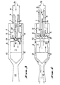
- Figure 1 is a longitudinal central section of the device according to this invention,
- Figure 2 is a schematic view showing the device with the stepped piston in a position where pressure gas is applied to its smaller end to project the stepped piston forwardly, the valve at this stage being closed,
- Figure 3 is a similar view but showing the piston in its fully forwardly projected position with the valve open, at which stage the pressure gas passes through the bore in the stepped piston and charges the pressure chamber in the body until the pressure in the chamber and in the bore is equalised whereupon the valve closes as shown and the device is set to be triggered, and
- Figure 4 is a similar view of Figures 2 and 3 but showing the condition when the smaller bore is vented to the atmosphere allowing the pressure from the pressure chamber to rapidly drive back the stepped piston until it uncovers circumferential ports which allow the high pressure gas flow to eject through the nozzle.
- The invention uses a
free piston 1 which is stepped in diameter to have a largerdiameter head portion 2 and asmaller diameter portion 3, and this piston is axially movable in abody 4 having a stepped bore 5-6 of the required diameter to allow the twoparts piston 1 to be accommodated in the selected diameters of the bore. - The
body 4 has in it at one end of the larger diameter bore 5 a gas storage chamber 7 into which pressure gas can be fed through a gas-transfer bore 8 through the steppedpiston 1, thesmaller bore 6 of the body communicating through atransfer aperture 9 with a threeport control valve 10, shown diagramatically in Figure 1, adapted to be connected to a pressure source which allows pressure to be built up within the device but also allows the pressure to be released from the small bore end through the three port control valve when a noise impulse is required. - The larger
diameter head portion 2 of thepiston 1 covers anannular port 11 when the steppedpiston 1 is projected forward in the bore to a triggered position, and this port leads to anannular space 12 which in turn terminates in a flarednozzle 14 from which the gas flow is distributed to the atmosphere to give the high intensity noise. - The stepped
piston 1 has at its head portion 2 a sealingvalve 15 which is loaded by aspring 16 in such a manner that gas caused to flow under pressure into the rear end of thesmaller bore 6 in thebody 4 will flow through thebore 8, which extends through the stepped piston, and through the sealingvalve 15, by opening the valve by differential pressure, and into the storage chamber 7 in thebody 4 until a balanced pressure is achieved throughout the unit. During forward movement of thepiston 1 the sealingvalve 15 is closed by the pressure of its spring, but when thepiston 1 reaches the forward end of its stroke, anextension 17 on thehead portion 2 of thepiston 1 fits into anopening 18 in awall 19 which divides the larger diameter bore 5 from the storage chamber 7, and the valve is then opened by the gas fed to it but closes again under action of thespring 16 when the pressure in the storage chamber 7 is equal to the pressure in the bore of the piston. Theextension 17 has an "0"ring seal 20 on it to seal to the wall of theopening 18. - In constructing the device the body is formed to have a
nozzle member 25 joined to the rear end of aninner cylinder 26 bytension rods 27, anouter cylinder 28 being positioned between thenozzle number 25 and the rear end of theinner cylinder 26 to form between the two cylinders theannufar space 12 which communicates on the one hand with the flarednozzle 14 of thenozzle number 25 and through theannular ports 11 with the bore in which the larger diameter head of the steppedpiston 1 operates. - The
cylinder 29 which defines thesmaller bore 6, has aflange 30 on it secured to therear end 31 of the inner cylinder by studs, not shown, and has acap 32 closing its end in which is formed theaperture 9 to which is connected a line to the threeport valve 10. - The dividing
wall 19 is held byspacers 33 to define between it and thenozzle member 25, the storage chamber 7. - The
larger diameter portion 2 of thepiston 1 has attached to it, by aflange 34, asupport member 36 which carries thevalve 15, thevalve 15 having astem 37 engaged by thespring 16, thesupport member 36 having aduct 38 through to allow gas flow from thebore 8 to thevalve 15 and past it, when open, into thestorage chamber 17, the body of thesupport member 36 being positioned in thebore 6 of the steppedpiston 1. - A
removable cap 39 is shown to normally close. the nozzle but this is removed before a noise is to be produced. - The
inner part 40 of thenozzle member 25 is joined to the outer part byspacers 41. - The operation of the device is as follows:
- Assuming that the stepped
piston 1 is in its retracted position in the stepped bore 5-6, gas such as air or nitrogen is caused to flow into thesmall bore 6 of the stepped cylinder causing the steppedpiston 1 to be projected forwardly because thevalve 15 at the other end of the steppedpiston 1 is held closed by thespring 16 which is arranged to act as a loading device. When however thepiston 1 reached the end of its traverse a seal is made between theextension 17 of the head of thepiston 1 and thewall 19 and thevalve 15 then opens to cause a flow of gas into the gas storage chamber 7 until equalization of the pressure in the chamber 7 and within the smaller diameter bore 6 is achieved. Thevalve 17 then closes. - The gas is preferably fed into the device by an electrically operated three
port valve 10 so arranged that in one position the valve admits gas to thesmall bore 6 of the body while in the other position it closes off the supply and vents part of the gas stored in thesmall bore 6 and the hollow of the piston to the atmosphere. - The cycle begins with the
piston 1 in any position along the cylinder, but when gas is admitted by thevalve 10 thepiston 1 is moved forward to what we term the triggered position where the piston seals to thewall 19 of the storage chamber and the valve in the head of the piston opens and gas flows into the storage chamber until the pressure on both sides of the piston is equalized and gas flow ceases. - At this stage the
piston 1 is held in a triggered position because the area of the back of thesmaller diameter portion 3 of the piston is greater than the area of theextension 17, and since the pressure is equalized there is a net force on the back of the piston. - When however the
control valve 10 is actuated the gas behind thepiston 1 vents to atmosphere and this causes the pressure in thebore 6 to fall until the pressure in the storage chamber 7, acting on theextension 17, causes the piston to move rearwardly. After the piston has moved a short distance the seal on theextension 17 separates from thewall 19 of the storage chamber 7 and this pressure then acts on the full face of thelarger diameter portion 2 of thepiston 1, the result of this being that the piston accelerates rapidly and has reached a high velocity by the time it begins to open theannular ports 11, which opening can take place in as short a time as 1 millisecond. The gas then flows through theports 11, along theannular space 12 and through thenozzle 14, where it forms a shock wave. - While the
piston 1 is being driven along the stepped bore 5-6 the gas behind the piston is venting through thecontrol valve 10 but because of gas flow resistance in the supply line and the relatively small size of thevalve 10 relatively little can escape during the rapid movement of thepiston 1 and the remainder is compressed until it again equals the pressure on the driving side, but acting on a much smaller area, at which point thevalve 15 opens again and most of the gas behind the smaller portion of thepiston 1 passes through thevalve 15 and takes part in the noise generation. - The piston is finally cushioned by the air which remains trapped in the
annular space 39 behind the main piston diameter, asmall bleed 40 being however provided. - From the foregoing it will be realized that a simple and effective device is provided which has only one major moving part in the nature of a stepped piston and valve.
- It will be realized also that the device can be remotely controlled because charging prior to an active stroke is effected simply by allowing a gas flow into the unit through the three
port valve 10 which as said can be electrically controlled and when it is desired to produce the noise it is only necessary to bleed some of the gas from the unit to the atmosphere for the explained sequence to occur.
Claims (9)
Applications Claiming Priority (2)
| Application Number | Priority Date | Filing Date | Title |
|---|---|---|---|
| AUPE327780 | 1980-04-24 | ||
| AU3277/80 | 1980-04-24 |
Publications (3)
| Publication Number | Publication Date |
|---|---|
| EP0052107A1 EP0052107A1 (en) | 1982-05-26 |
| EP0052107A4 EP0052107A4 (en) | 1983-07-04 |
| EP0052107B1 true EP0052107B1 (en) | 1985-09-25 |
Family
ID=3768502
Family Applications (1)
| Application Number | Title | Priority Date | Filing Date |
|---|---|---|---|
| EP81900958A Expired EP0052107B1 (en) | 1980-04-24 | 1981-04-10 | Impulse noise generator |
Country Status (5)
| Country | Link |
|---|---|
| US (1) | US4432299A (en) |
| EP (1) | EP0052107B1 (en) |
| JP (1) | JPS57500802A (en) |
| CA (1) | CA1179764A (en) |
| WO (1) | WO1981003081A1 (en) |
Families Citing this family (9)
| Publication number | Priority date | Publication date | Assignee | Title |
|---|---|---|---|---|
| EP0238736B1 (en) * | 1986-03-20 | 1990-04-25 | British Gas Corporation | Seismic pulse generation |
| US5302938A (en) * | 1992-12-07 | 1994-04-12 | Mark Martineau | Sound generating device for firearm, bow or the like |
| GB2296564B (en) * | 1994-12-23 | 1999-02-24 | British Gas Plc | A method for producing seismic pulses |
| US6717537B1 (en) | 2001-06-26 | 2004-04-06 | Sonic Innovations, Inc. | Method and apparatus for minimizing latency in digital signal processing systems |
| US7434988B1 (en) | 2006-05-17 | 2008-10-14 | Enertechnix, Inc. | Low pressure acoustic pyrometer signal generator |
| CN105688411B (en) * | 2015-04-16 | 2018-06-08 | 王新明 | A kind of acoustic generator |
| RU2659185C1 (en) * | 2017-03-07 | 2018-06-28 | Федеральное государственное бюджетное образовательное учреждение высшего образования "Санкт-Петербургский государственный университет" (СПбГУ) | Device for dynamic calibration of acoustic pressure pulsation sensors |
| RU176017U1 (en) * | 2017-03-09 | 2017-12-26 | Федеральное государственное бюджетное образовательное учреждение высшего образования "Санкт-Петербургский государственный университет" (СПбГУ) | Pneumatic sound pulsation generator |
| CN108654064A (en) * | 2018-05-23 | 2018-10-16 | 陕西理工大学 | A kind of sport starting apparatus |
Family Cites Families (9)
| Publication number | Priority date | Publication date | Assignee | Title |
|---|---|---|---|---|
| US2991781A (en) * | 1958-03-19 | 1961-07-11 | Marvin I Glass | Toy |
| US3249177A (en) * | 1961-11-13 | 1966-05-03 | Bolt Associates Inc | Acoustic wave impulse generator repeater |
| US3379272A (en) * | 1965-11-26 | 1968-04-23 | Navy Usa | Pneumatic explosion generator |
| US3457893A (en) * | 1966-12-29 | 1969-07-29 | Hart Carter Co | Interruptible-jet control means for producing short blasts of high pressure fluid |
| FR1543553A (en) * | 1967-10-09 | 1968-10-25 | Ramenskoe Otdel Vnii Geofiz | Device for the production of elastic oscillations in liquid media |
| DE1728077C1 (en) * | 1968-08-21 | 1978-02-09 | Messerschmitt Boelkow Blohm | Differential pressure piston combustion chamber system for the production of propellant gases, especially for firearms |
| US3638752A (en) * | 1968-09-13 | 1972-02-01 | Commercial Solvents Corp | Seismic signal generator |
| US3837424A (en) * | 1972-01-26 | 1974-09-24 | Texaco Inc | Highly penetrating seismic energy sound generator with pulse shaping for offshore subsurface exploration |
| BR7602346A (en) * | 1975-04-18 | 1977-10-25 | Dev De La Rech Appliquee Soc P | PROCESS TO GENERATE AN ACOUSTIC IMPULSE, GENERATOR OF AN ACOUSTIC IMPULSE IN LIQUID MASS AND SEA SYSTEMATIC EXPLORATION PROCESS |
-
1981
- 1981-04-10 US US06/339,446 patent/US4432299A/en not_active Expired - Fee Related
- 1981-04-10 WO PCT/AU1981/000043 patent/WO1981003081A1/en not_active Ceased
- 1981-04-10 JP JP56501209A patent/JPS57500802A/ja active Pending
- 1981-04-10 EP EP81900958A patent/EP0052107B1/en not_active Expired
- 1981-04-15 CA CA000375593A patent/CA1179764A/en not_active Expired
Also Published As
| Publication number | Publication date |
|---|---|
| EP0052107A4 (en) | 1983-07-04 |
| EP0052107A1 (en) | 1982-05-26 |
| WO1981003081A1 (en) | 1981-10-29 |
| CA1179764A (en) | 1984-12-18 |
| JPS57500802A (en) | 1982-05-06 |
| US4432299A (en) | 1984-02-21 |
Similar Documents
| Publication | Publication Date | Title |
|---|---|---|
| US5538172A (en) | Explosive powder charge operated setting tool | |
| US5962805A (en) | Gas cartridge | |
| US3921614A (en) | Compressed gas operated gun having variable upper and lower pressure limits of operation | |
| DE69700825T2 (en) | AIR PRESSURE WEAPON FOR SHOOTING BULLETS AND METHOD FOR SHOOTING A BULLET | |
| US5450839A (en) | Pneumatic launcher | |
| AU670206B2 (en) | Model gun with automatic bullet supplying mechanism | |
| US2809624A (en) | Missile firing trainer device | |
| US4040334A (en) | Missile launcher for aircraft | |
| US5016536A (en) | Non-lethal practice round for automatic and semiautomatic firearms | |
| US3548708A (en) | Pneumatic missile launcher | |
| MXPA04006985A (en) | Toy gun using gas pressure. | |
| US4432299A (en) | Impulse noise generator | |
| EP0199817A1 (en) | Pneumatic weapon | |
| US5857854A (en) | Recoil simulator for a weapon | |
| AU9611298A (en) | Model gun with automatic bullet supplying mechanism | |
| US4534500A (en) | Setting device with a driving piston propelled by high pressure gases | |
| US6123242A (en) | Explosive powder charge operated bolt-setting tool | |
| CA2304621A1 (en) | Pneumatically operated projectile launching device | |
| GB1600268A (en) | Automatic gun | |
| US3334425A (en) | Weapon fire simulator | |
| US4099465A (en) | Ignition device for missile motors | |
| JP2023511768A (en) | Improvements in or relating to trigger valves of high pressure fluid operated devices | |
| US3735747A (en) | Underwater compressed-gas gun | |
| US4815694A (en) | High speed, high volume gas pulse generator | |
| US4601278A (en) | Ammunition cartridge |
Legal Events
| Date | Code | Title | Description |
|---|---|---|---|
| PUAI | Public reference made under article 153(3) epc to a published international application that has entered the european phase |
Free format text: ORIGINAL CODE: 0009012 |
|
| 17P | Request for examination filed |
Effective date: 19820112 |
|
| AK | Designated contracting states |
Designated state(s): DE FR GB NL SE |
|
| GRAA | (expected) grant |
Free format text: ORIGINAL CODE: 0009210 |
|
| AK | Designated contracting states |
Designated state(s): DE FR GB NL SE |
|
| REF | Corresponds to: |
Ref document number: 3172405 Country of ref document: DE Date of ref document: 19851031 |
|
| ET | Fr: translation filed | ||
| PG25 | Lapsed in a contracting state [announced via postgrant information from national office to epo] |
Ref country code: SE Effective date: 19860411 |
|
| PLBE | No opposition filed within time limit |
Free format text: ORIGINAL CODE: 0009261 |
|
| STAA | Information on the status of an ep patent application or granted ep patent |
Free format text: STATUS: NO OPPOSITION FILED WITHIN TIME LIMIT |
|
| 26N | No opposition filed | ||
| PG25 | Lapsed in a contracting state [announced via postgrant information from national office to epo] |
Ref country code: NL Effective date: 19861101 |
|
| NLV4 | Nl: lapsed or anulled due to non-payment of the annual fee | ||
| GBPC | Gb: european patent ceased through non-payment of renewal fee | ||
| PG25 | Lapsed in a contracting state [announced via postgrant information from national office to epo] |
Ref country code: FR Free format text: LAPSE BECAUSE OF NON-PAYMENT OF DUE FEES Effective date: 19861231 |
|
| PG25 | Lapsed in a contracting state [announced via postgrant information from national office to epo] |
Ref country code: DE Effective date: 19870101 |
|
| REG | Reference to a national code |
Ref country code: FR Ref legal event code: ST |
|
| PG25 | Lapsed in a contracting state [announced via postgrant information from national office to epo] |
Ref country code: GB Effective date: 19881118 |
|
| EUG | Se: european patent has lapsed |
Ref document number: 81900958.0 Effective date: 19870224 |