EP0052037A2 - Contact perçant d'isolation - Google Patents
Contact perçant d'isolation Download PDFInfo
- Publication number
- EP0052037A2 EP0052037A2 EP81401659A EP81401659A EP0052037A2 EP 0052037 A2 EP0052037 A2 EP 0052037A2 EP 81401659 A EP81401659 A EP 81401659A EP 81401659 A EP81401659 A EP 81401659A EP 0052037 A2 EP0052037 A2 EP 0052037A2
- Authority
- EP
- European Patent Office
- Prior art keywords
- sleeve
- wire
- insulation piercing
- insulation
- contact
- Prior art date
- Legal status (The legal status is an assumption and is not a legal conclusion. Google has not performed a legal analysis and makes no representation as to the accuracy of the status listed.)
- Granted
Links
Images
Classifications
-
- H—ELECTRICITY
- H01—ELECTRIC ELEMENTS
- H01R—ELECTRICALLY-CONDUCTIVE CONNECTIONS; STRUCTURAL ASSOCIATIONS OF A PLURALITY OF MUTUALLY-INSULATED ELECTRICAL CONNECTING ELEMENTS; COUPLING DEVICES; CURRENT COLLECTORS
- H01R4/00—Electrically-conductive connections between two or more conductive members in direct contact, i.e. touching one another; Means for effecting or maintaining such contact; Electrically-conductive connections having two or more spaced connecting locations for conductors and using contact members penetrating insulation
- H01R4/24—Connections using contact members penetrating or cutting insulation or cable strands
- H01R4/2491—Connections using contact members penetrating or cutting insulation or cable strands the contact members penetrating the insulation being actuated by conductive cams or wedges
-
- H—ELECTRICITY
- H01—ELECTRIC ELEMENTS
- H01R—ELECTRICALLY-CONDUCTIVE CONNECTIONS; STRUCTURAL ASSOCIATIONS OF A PLURALITY OF MUTUALLY-INSULATED ELECTRICAL CONNECTING ELEMENTS; COUPLING DEVICES; CURRENT COLLECTORS
- H01R43/00—Apparatus or processes specially adapted for manufacturing, assembling, maintaining, or repairing of line connectors or current collectors or for joining electric conductors
- H01R43/01—Apparatus or processes specially adapted for manufacturing, assembling, maintaining, or repairing of line connectors or current collectors or for joining electric conductors for connecting unstripped conductors to contact members having insulation cutting edges
- H01R43/015—Handtools
Definitions
- the present invention relates to an electrical contact for piercing the insulation of a discrete electrical wire to make a strain relieved electrical connection therewith and in particular to an insulation piercing contact including a pair of coaxial sleeves slidably disposed to deflect a wire piercing end on a cantilevered arm into electrical connection with the wire.
- Controlling the crimp depth is established by ratchet means on the crimping tool which allow the crimping tool's handles to reach full closure (representing the bottoming position of the crimping operation) and the indentor to be released. Irrespective of contact sleeve size, the crimping mechanism release point and indentor bottoming position must be selected by the operator.
- wire must be prepared first.
- a wire stripping operation is not only time consuming but care must be taken in selecting the tool which strips the insulation so as to avoid damage to the conductors.
- a further disadvantage with the above method is that the tool operator could mistakenly select improper crimping settings, thereby resulting in poor and/or unacceptable terminated wire-to-contact interconnections.
- Another method of electrically terminating an insulated wire is by an insulation displacement technique.
- the insulation displacement method of terminating a wire to an electrical contact requires no previous removal of the insulation from a wire before assembly.
- the wire typically lays across a pair of spaced slots.
- An assembly tool typically wedges each wire home into a slot of the contact receiving the wire and a contact portion pierces and/or displaces the insulation surrounding the conductive wire portion.
- Typical examples of insulation piercing contacts are illustrated by US Patents 3 012 219 ; 3 147 058 ; 3 617 983 ; 3 879 099 and 3 964 816.
- a major disadvantage with the above technique is the need for a plastic (molding) housing to retain the insulated conductors in the terminated position. Without this protection, the terminated connection will not be locked in place and the interconnection would not be strain relieved.
- a further disadvantage with this method is that the assembly tool must bear down onto the housing to force the wire inwardly of a wire receiving slot of the contact. The reliability of the termination in the slot is not certain. In some multi-termination apparatus shown by the prior art, to replace one contact-to-conductor termination, all of the terminations need to be dislodged and then reestablished.
- a more desirable contact would be one which provides the user with a contact that is self-contained, which provides means for assuring that the wire is properly positioned for termination, which may be used without requiring a separate housing molding, which provides a sturdy insulation piercing member, which encloses the wire and strain relieves the termination and which locks the contact and the wire termination achieved.
- the invention proposes an insulation piercing contact for making electrical and mechanical engagement with an associated insulated conductor wire, characterized in that it comprises a first sleeve, a second sleeve having a wire receiving end, the second sleeve being telescopically interfittable with and slidably disposed relative to the first sleeve for axial movement between first and second positions which define electrically unconnected and electrically interconnected positions respectively with the wire, and a deflectable cantilever arm extending from said second sleeve, said cantilever arm having a pointed end to pierce through the insulation of the wire inserted into the second sleeve, the first sleeve of said telescoped sleeves having a cam disposed to urge against and deflect the cantilever arm and pointed end into wire when the second sleeve slides between the two axial positions.
- the invention comprises an electrical contact comprising a central body member having a shoulder, a mateable portion extending forwardly from the body and an insulation piercing portion extending rearwardly from the central body, the insulation piercing portion including a pair of coaxial sleeves telescopically interfitted one over the other and adapted to be slidably displaced by jaws of a tool from a first to a second axial position defining respectively electrically unconnected and electrically terminated conditions.
- the insulation piercing portion comprises the first (outer) sleeve having a pair of openings adapted to receive therethrough one of a like pair of cantilever arms extending outwardly at an acute angle from the second (inner) sleeve, each cantilever arm having one end secured at its root adjacent an inner sleeve axial slot exposing the wire end and having a sharp pointed end extending threfrom for piercing the insulation, each of the arms being deflected downward by an edge of each opening being cammed against the arm as the sleeves are moved from the first to the second positions. As the cantilever arms are deflected downwardly, the sharp pointed ends cut into and through the insulation to make electrical contact with the conductive portion of the wire.
- Each of the openings and cantilever arms cooperate to provide means for detaining the two sleeves in the first (unconnected) position and the openings cooperate with the slots to provide the user with means for visually inspecting whether or not the wire has been fully seated within the inner sleeve and against a wire stop prior to sliding the sleeves to the second (connected) position.
- the contact is capable of providing a self-locking termination. Prior preparation of wires is eliminated.
- the contact itself may, if desired, be used without a surrounding molding or connector body assembly.
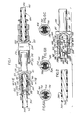
- FIG. 1 illustrates partially in section an electrical interconnection between a pin contact 100, a socket contact 200 and a pair of insulated wires 300, 400.
- Each axially extending contact 100, 200 is similar and comprises, respectively, a central body member 120, 220 having a shoulder 121, 221 and a pair of oppositely disposed radial abutment faces, a mating portion 110, 210 extending axially forwardly from the central body, means including a pair of sleeves extending axially rearwardly from the central body for terminating one wire end and releasable means for locking the wires in the terminated position.
- Each insulated wire 300, 400 is similar and comprises, respectively, an outer cover 301, 401 of insulative material which circumposes an inner core 302, 402 of conductive material. The inner core could be stranded or solid.
- the contact mating portions 110, 210 are shown as comprising a tubular pin 111 designed for telescopic engagement with a socket 211, the socket being formed by a pair of spring members 212 and a hood 213.
- the mating portions could be other than that shown and could include hermaphroditic "brush-type" mating ends such as shown by the US Patent 3 725 844 filed March 15, 1971 and entitled "Hermaphroditic Electrical Contact".
- each contact 100, 200 is adapted to be used in a separable electrical connector assembly (not shown) comprised of a pair of electrical connector members, one of said connector members being a receptacle and the other being a plug adapted to mate with the receptacle, each of the connector members including a dielectric insert with at least one socket contact 200 being mounted in the insert of one member and the pin contact 100 corresponding to the socket contact being mounted in the insert of the other member and adapted for mating engagement with the socket contact when the plug and receptacle are in mated relationship.
- a suitable assembly is shown in US Patent 4 082 398 filed October 21, 1976 and entitled "Electrical Connector with Front and Rear Insertable and Removable Contacts". Free ends of retention fingers disclosed therein face each other to define a cavity captivating an enlarged portion of a contact such as shoulders 120, 220 of the contacts herein.
- the wire terminating means 500 include a first outer sleeve 510 defining an interior bore and having one end 511 secured to the body 120 and the other end 512 extending axially rearward therefrom, a second inner sleeve 520 defining an interior bore and coaxial with and telescopically interfitted within the first sleeve and provided with a forward end portion 521, a rearward wire receiving end portion 522 and a pair of medial diametrically opposed cantilever arms 600 including pointed ends 700, the inner sleeve 520 being circumposed about the wire end and the pointed ends 700 being pierced through the wire insulation 301 to make electrical contact with the conductive inner core 302 of the wire.
- Figure 2 illustrates the terminable end portion of the wire 300 about to be inserted into the wire receiving end portion 522 of the pin contact 100.
- the description to follow is equally applicable to the socket contact 200.
- the outer sleeve 510 is axially extending and includes a generally peripherally closed tube defined by a wall 513 having a pair of diametrically spaced openings 514 axially spaced from the mating end of the contact, the rearward end 512 thereof having a radial face 518.
- Each opening 514 has a pair of axially spaced ends 515, 516'with the rearward end 515 defining a cam-like edge.
- the inner sleeve 520 is axially extending and includes a generally peripherally closed tube defined by a wall 523 and a pair of diametrically disposed slots 524 having spaced axial ends 525, 526, the slots 524 being in register with the openings 514.
- the inner sleeve 520 is coaxial with and sized to slidably fit within the outer sleeve 510 and adapted to be axially displaced between a first and electrically unconnected contact position to a second and electrically terminated contact position. As shown in Figure 2, the sleeves are disposed in the first and electrically unconnected position. Forward and rearward end portions respectively of the inner sleeve 520 interfit within and extend outwardly of the outer sleeve 510.
- the rearward wire receiving end portion 522 of the inner sleeve 520 includes a transverse reinforced radial lip 528.
- the rearward end portion of the inner sleeve is adapted to clearance fit about the terminable end portion of the wire and to . strain relieve the resulting termination.
- the releasable means for locking the sleeves in the second (and electrically terminated) position includes a resilient lance 800 struck from the rear end portion wall 523 of the inner sleeve 520, the lance having a root 801 and a free end 802 adapted to spring radially outwardly from the inner sleeve when the inner sleeve is displaced to the second position, the free end 802 butting against the radial face 518 of the outer sleeve.
- the lance 800 is disposed about 90° from both the slots 524 and the openings 514.
- the cantilever arms 600 are struck from the wall 523 and are resiliently deflectable inwardly and outwardly of the inner sleeve outer surface relative to their roots 601 secured to like axial rearward ends 525 of the respective slots 524, each arm 600 extending divergently outward from the sleeve at an acute angle to a deflectable free end 602.
- An abutment shoulder 604 is disposed forwardly of the root 601 on the exterior surface 603.
- the cantilever arms 600 are adapted to extend through the respective openings 514 whereby the two sleeves are detained together (and ready for receiving a wire end) in the first position.
- the cantilever arms 600 include the sharp insulation piercing points 700 at their free ends 602, each of the points converging towards one another and towards the sleeves. In some applications, one deflectable cantilever arm may be adequate. However, at least two cantilever arms are preferable to distribute stresses uniformly about the sleeves when the sleeves are displaced during wire termination and to increase electrical contact redundancy.
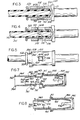
- Figure 3 illustrates the pin contact 100 having received the insulated wire 300 with the inner sleeve 520 being disposed in the first position and with the wire end disposed in its most forward position prior to termination.
- the interior junction of the outer sleeve 510 with the body 120 defines a wire stop 121 which tells the user that the wire has been properly received for terminating.
- the register position of slot 524 with opening 514 allows a visual inspection of the wire fitment prior to termination.
- Figure 4 shows the inner sleeve 520 displaced into the second (axially rearward) position relative to the outer sleeve 510 representing the final terminated connection.
- the pointed tips 700 are shown pierced through the wire insulation 301 and contacting the conductive portion 302.
- the cam-like edge 515 of opening 514 is abutted against the shoulder 604 of the cantilever 600 firmly seating the arm in the deflected position.
- Figure 5 illustrates the final terminated connection of Figure 4 rotated 90° showing the lance 800 locking the sleeves apart in the termination position, the lance free end 802 abutted against the rearward radial face 518 of the outer sleeve 510.
- Figure 6A shows one embodiment of the pin contact 100 insulation piercing end 700.
- the pointed end 700 is concave, elongated V-shaped and includes one sharp spear tip 710. In the situation where the conductive wire portion is stranded the tip of the spear makes contact with a greater number of stranded wires.
- Figure 6B illustrates an alternate embodiment of the insulation piercing end 700.
- the pointed end 700 is convex, v-shaped and defines two pointed biting tips 720.
- the elongated V-shape makes contact with a greater number of stranded wires.
- Figure 6C illustrates another alternate embodiment of the insulation piercing end 700.
- the contact end is circular shaped having distal points 730 and is preferably for penetrating a solid'insulated conductor.
- FIG. 7 illustrates an alternate embodiment of the invention.
- a socket-type contact 900 including a body 910 having a central shoulder 911, a tubular wire receiving inner sleeve 920 extending rearwardly from the shoulder, a wire stop 912 interiorly disposed in the inner sleeve, a mating portion 930 extending forwardly from the shoulder, wire insulation piercing means 940 and terminated wire locking means 950.
- a separate terminating outer sleeve 960 is slidably assembled over the inner sleeve 920.
- the mating portion 930 includes a tubular hood 931 pressed over a pair of spring members 932 to define the socket.
- the mating portion could equally be provided with the pin-type contact or with "brush-type" contacts.
- the inner sleeve 920 includes a pair of diametrically opposed slots 921 having axial ends 922, 923.
- the (outer) terminating sleeve 960 is axially extending and includes free axial ends 961, 962 with the forward axial end 961 thereof defining a cam-like edge and the rearward axial end 962 having a radially flared portion 963 adapted to provide an engagement surface for an installation tool.
- the insulation piercing means 940 comprises a pair of cantilever arms 941 having their root ends 942 secured to the rearward axial end 923 of the inner sleeve 920,slot 921 and a deflectable free end 943 provided with a sharp wire penetrating portion 970.
- Each of the arms extend (diverge) outwardly from the inner sleeve 920 and from one another and the penetrating portions 970 converge inwardly towards one another.
- the locking means 950 comprise the inner sleeve 920 having struck therefrom an outwardly extending lance or finger 951 having an end 952 adapted to flex inwardly and outwardly to engage the flared end 962 of the outer sleeve 960.
- Electrical termination is achieved by moving the outer sleeve 960 from the first (electrically unconnected) position axially towards the body 910 and to a second (electrically terminated) position.
- Figure 8 illustrates the socket contact assembly of Figure 9 with the inner sleeve 960 locked in the second (electrically terminated) position by the end 952 of finger 951.
- the insulated wire is omitted for clarity.
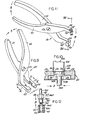
- a plier-like tool in operation, would be utilized to grip the contact and advance the contact sleeves between the first and second axial positions.
- a first plier-type tool 20 for use with the electrical contacts 100, 200 comprises a pair of body members 21, 22 pivotally coupled by a pin 23 with each body including a handle and a jaw,. the body members being adapted to move in a direction "A" to complete the termination between the contact and the conductor 300.
- Each jaw 24, 25 includes a pair of chamfered surfaces 26, 28.
- the contact 100 is positioned in the recess such that the tool surfaces 26 position against the contact edge 518 and the tool surfaces 28 position against the contact lip 528.
- the operator would cause the body parts to move in the direction "A" causing the edges 26, 28 to cam against the contact surfaces 518, 528, whereby the sleeves axially displace away from one another.
- Continued motion of the jaws 24, 25 causes the sleeve 510 to cam against the cantilever arms 600 and deflect them and their pointed ends 700 downwardly, driving the pointed ends into the wire received therein.
- the user By continued squeezing together of the jaws the user knows the final terminated position is achieved when the lance 800 on the inner sleeve 520 snaps outwardly against the radial face 518 of the outer sleeve 510 and the cam edge 515 abuts the cantilever arm shoulder 604.
- the shoulder 604 serves to limit axial movement of the inner sleeve and the lance assures the user that the termination is "locked”.
- a plier type tool 40 for use with the electrical contact 900 comprises a pair of body members 41, 42 pivotally coupled by a pin 43 with each body member including a handle and a jaw, the body members (and jaws) being adapted to move in a direction "B" to terminate the contact with the wire.
- One jaw 44 comprises a pair of positioning tongues 46, 47 spaced apart by a small amount to define a slot 48 disposed therebetween.
- the other jaw 45 comprises a body part 49 having a bore 50 disposed therein.
- the contact 900 is seated in the pliers 40 with the forward part 930 of the contact being disposed in the bore 50.
- a force is exerted against surface 963 of sleeve 960.
- the outer sleeve end 961 cams against the cantilevers 941 and deflects them downwardly as the outer sleeve 960 moves forwardly and about the inner sleeve 920.
- Outer sleeve 960 will move forwardly until surface 961 butts against the shoulder 911 of contact body 910.
- the inner sleeve end 952 will pass axially rearwardly and seat beyond surface 962 of the outer sleeve 960, thereby allowing the finger 951 to spring radially outwardly and capture the outer sleeve 960.
- the contact in either embodiment would be stamped from flat metal stock and rolled into the desired shape although other expedients are possible. However, to reduce cost of manufacture or flexibility of use, some portions could be of insulative material (e.g. sleeve 960).
Applications Claiming Priority (2)
| Application Number | Priority Date | Filing Date | Title |
|---|---|---|---|
| US06/205,204 US4370014A (en) | 1980-11-07 | 1980-11-07 | Insulated wire termination device |
| US205204 | 1980-11-07 |
Publications (3)
| Publication Number | Publication Date |
|---|---|
| EP0052037A2 true EP0052037A2 (fr) | 1982-05-19 |
| EP0052037A3 EP0052037A3 (en) | 1982-12-15 |
| EP0052037B1 EP0052037B1 (fr) | 1985-12-11 |
Family
ID=22761243
Family Applications (1)
| Application Number | Title | Priority Date | Filing Date |
|---|---|---|---|
| EP81401659A Expired EP0052037B1 (fr) | 1980-11-07 | 1981-10-21 | Contact perçant d'isolation |
Country Status (5)
| Country | Link |
|---|---|
| US (1) | US4370014A (fr) |
| EP (1) | EP0052037B1 (fr) |
| JP (1) | JPS57107578A (fr) |
| CA (1) | CA1159919A (fr) |
| DE (1) | DE3173213D1 (fr) |
Cited By (5)
| Publication number | Priority date | Publication date | Assignee | Title |
|---|---|---|---|---|
| EP0131705A1 (fr) * | 1983-06-20 | 1985-01-23 | Allied Corporation | Terminal et méthode pour connecter celui-ci électriquement au conducteur central d'un câble isolé |
| US4512619A (en) * | 1982-07-23 | 1985-04-23 | Molex Incorporated | Insulation displacement terminal for an electrical connector _and environmental sealing means therefor |
| GB2289578A (en) * | 1994-05-21 | 1995-11-22 | Hawke Cable Glands Ltd | Glands for terminating cables and pipes |
| DE10257088B4 (de) * | 2002-12-05 | 2011-07-07 | Amphenol-Tuchel Electronics GmbH, 74080 | Kontakt mit einem Kontaktteil und einem Leiterbefestigungsteil sowie Klemmsanschluss |
| DE102014116482A1 (de) * | 2014-11-12 | 2016-05-12 | Amphenol-Tuchel Electronics Gmbh | Kontaktelement |
Families Citing this family (3)
| Publication number | Priority date | Publication date | Assignee | Title |
|---|---|---|---|---|
| US4614395A (en) * | 1985-04-04 | 1986-09-30 | Cordis Corporation | Quick connector to medical electrical lead |
| US5026301A (en) * | 1990-05-21 | 1991-06-25 | Itt Corporation | Lead termination |
| WO2017144072A1 (fr) * | 2016-02-26 | 2017-08-31 | Rosenberger Hochfrequenztechnik Gmbh & Co. Kg | Connecteur électrique enfichable |
Citations (3)
| Publication number | Priority date | Publication date | Assignee | Title |
|---|---|---|---|---|
| US3861772A (en) * | 1973-09-13 | 1975-01-21 | Amp Inc | Insulation piercing contact and connector |
| US3879099A (en) * | 1973-09-04 | 1975-04-22 | Amp Inc | Flat fexible cable connector assembly including insulation piercing contacts |
| US4154497A (en) * | 1976-03-18 | 1979-05-15 | International Standard Electric Corporation | Stripless electrical contact |
Family Cites Families (6)
| Publication number | Priority date | Publication date | Assignee | Title |
|---|---|---|---|---|
| US2419683A (en) * | 1942-12-26 | 1947-04-29 | American Bosch Corp | Sealing high-tension wires in sockets |
| US2534881A (en) * | 1946-04-20 | 1950-12-19 | Henry J Schroeder | Electrical wire connector with insulation piercing means |
| US2702895A (en) * | 1951-01-04 | 1955-02-22 | Pavlinetz George | Terminal connector |
| GB1109914A (en) * | 1965-09-28 | 1968-04-18 | Eric Lionel Hutchings | Improvements in or relating to coaxial cable connectors |
| US3553631A (en) * | 1968-11-27 | 1971-01-05 | Shlesinger Jr Bernard E | Nonstrip connection |
| US4261632A (en) * | 1979-04-09 | 1981-04-14 | Thomas & Betts Corporation | Coaxial cable connector |
-
1980
- 1980-11-07 US US06/205,204 patent/US4370014A/en not_active Expired - Lifetime
-
1981
- 1981-08-20 CA CA000384288A patent/CA1159919A/fr not_active Expired
- 1981-10-21 DE DE8181401659T patent/DE3173213D1/de not_active Expired
- 1981-10-21 EP EP81401659A patent/EP0052037B1/fr not_active Expired
- 1981-11-06 JP JP56177272A patent/JPS57107578A/ja active Pending
Patent Citations (3)
| Publication number | Priority date | Publication date | Assignee | Title |
|---|---|---|---|---|
| US3879099A (en) * | 1973-09-04 | 1975-04-22 | Amp Inc | Flat fexible cable connector assembly including insulation piercing contacts |
| US3861772A (en) * | 1973-09-13 | 1975-01-21 | Amp Inc | Insulation piercing contact and connector |
| US4154497A (en) * | 1976-03-18 | 1979-05-15 | International Standard Electric Corporation | Stripless electrical contact |
Cited By (8)
| Publication number | Priority date | Publication date | Assignee | Title |
|---|---|---|---|---|
| US4512619A (en) * | 1982-07-23 | 1985-04-23 | Molex Incorporated | Insulation displacement terminal for an electrical connector _and environmental sealing means therefor |
| EP0131705A1 (fr) * | 1983-06-20 | 1985-01-23 | Allied Corporation | Terminal et méthode pour connecter celui-ci électriquement au conducteur central d'un câble isolé |
| GB2289578A (en) * | 1994-05-21 | 1995-11-22 | Hawke Cable Glands Ltd | Glands for terminating cables and pipes |
| US5648639A (en) * | 1994-05-21 | 1997-07-15 | Hawke Cable Glands Limited | Glands for terminating cables and pipes |
| GB2289578B (en) * | 1994-05-21 | 1997-09-17 | Hawke Cable Glands Ltd | Glands for terminating cables and pipes |
| DE10257088B4 (de) * | 2002-12-05 | 2011-07-07 | Amphenol-Tuchel Electronics GmbH, 74080 | Kontakt mit einem Kontaktteil und einem Leiterbefestigungsteil sowie Klemmsanschluss |
| DE102014116482A1 (de) * | 2014-11-12 | 2016-05-12 | Amphenol-Tuchel Electronics Gmbh | Kontaktelement |
| DE102014116482B4 (de) | 2014-11-12 | 2021-09-23 | Amphenol-Tuchel Electronics Gmbh | Kontaktelement |
Also Published As
| Publication number | Publication date |
|---|---|
| JPS57107578A (en) | 1982-07-05 |
| US4370014A (en) | 1983-01-25 |
| CA1159919A (fr) | 1984-01-03 |
| DE3173213D1 (en) | 1986-01-23 |
| EP0052037A3 (en) | 1982-12-15 |
| EP0052037B1 (fr) | 1985-12-11 |
Similar Documents
| Publication | Publication Date | Title |
|---|---|---|
| US6089903A (en) | Electrical connector with automatic conductor termination | |
| US5647119A (en) | Cable terminating tool | |
| US5845393A (en) | Connector assembly tool | |
| US6036540A (en) | Coaxial connector with ring contact having cantilevered fingers | |
| US7500868B2 (en) | Compression connector for stranded wire | |
| US6027373A (en) | Electrical connectors | |
| US7226308B1 (en) | Compression snap electrical connector | |
| US3525107A (en) | Terminal crimping,wirecutting and insulation stripping tool | |
| US4335930A (en) | Toolless phone plug | |
| US7520772B2 (en) | Compression snap electrical connector | |
| US4690481A (en) | Coaxial coupling | |
| US6134774A (en) | Clamp for clamping coaxial cable connectors to coaxial cables | |
| US9059573B2 (en) | Cutting, stripping and crimping all-in-one tool | |
| US4133594A (en) | Self-locking connector | |
| US4445748A (en) | Mass termination of densely grouped conductors | |
| US4370014A (en) | Insulated wire termination device | |
| EP0800715B1 (fr) | Appareil d'evasement des fils de blindage d'un cable coaxial | |
| US6684439B2 (en) | Coaxial cable termination tool | |
| JP3044378U (ja) | 電気コネクタ用のフラットな絶縁被覆切り込み端子 | |
| NZ272490A (en) | Electrical connection between contact element and corresponding conductor: slot in conductor part receives with compression fit contact element having formed end | |
| JPH01232680A (ja) | 圧着コネクタおよびその取付け方法 | |
| US5628644A (en) | Negligible insert force power connector | |
| US4796358A (en) | Method and apparatus for assembly of electrical cable | |
| US4946407A (en) | High current connectors and methods of assembly | |
| EP0027065B1 (fr) | Method de fabrication d'un contact électrique |
Legal Events
| Date | Code | Title | Description |
|---|---|---|---|
| PUAI | Public reference made under article 153(3) epc to a published international application that has entered the european phase |
Free format text: ORIGINAL CODE: 0009012 |
|
| 17P | Request for examination filed |
Effective date: 19811027 |
|
| AK | Designated contracting states |
Designated state(s): DE FR GB IT |
|
| PUAL | Search report despatched |
Free format text: ORIGINAL CODE: 0009013 |
|
| AK | Designated contracting states |
Designated state(s): DE FR GB IT |
|
| ITF | It: translation for a ep patent filed |
Owner name: ING. ZINI MARANESI & C. S.R.L. |
|
| GRAA | (expected) grant |
Free format text: ORIGINAL CODE: 0009210 |
|
| AK | Designated contracting states |
Designated state(s): DE FR GB IT |
|
| PG25 | Lapsed in a contracting state [announced via postgrant information from national office to epo] |
Ref country code: FR Free format text: THE PATENT HAS BEEN ANNULLED BY A DECISION OF A NATIONAL AUTHORITY Effective date: 19851211 |
|
| REF | Corresponds to: |
Ref document number: 3173213 Country of ref document: DE Date of ref document: 19860123 |
|
| EN | Fr: translation not filed | ||
| PLBE | No opposition filed within time limit |
Free format text: ORIGINAL CODE: 0009261 |
|
| STAA | Information on the status of an ep patent application or granted ep patent |
Free format text: STATUS: NO OPPOSITION FILED WITHIN TIME LIMIT |
|
| 26N | No opposition filed | ||
| GBPC | Gb: european patent ceased through non-payment of renewal fee | ||
| PG25 | Lapsed in a contracting state [announced via postgrant information from national office to epo] |
Ref country code: DE Effective date: 19870701 |
|
| PG25 | Lapsed in a contracting state [announced via postgrant information from national office to epo] |
Ref country code: GB Effective date: 19881118 |