EP0052012A1 - Indication system for a four-wheel drive vehicle - Google Patents
Indication system for a four-wheel drive vehicle Download PDFInfo
- Publication number
- EP0052012A1 EP0052012A1 EP81305330A EP81305330A EP0052012A1 EP 0052012 A1 EP0052012 A1 EP 0052012A1 EP 81305330 A EP81305330 A EP 81305330A EP 81305330 A EP81305330 A EP 81305330A EP 0052012 A1 EP0052012 A1 EP 0052012A1
- Authority
- EP
- European Patent Office
- Prior art keywords
- wheels
- wheel drive
- speeds
- indication system
- main driving
- Prior art date
- Legal status (The legal status is an assumption and is not a legal conclusion. Google has not performed a legal analysis and makes no representation as to the accuracy of the status listed.)
- Withdrawn
Links
Images

Classifications
-
- B—PERFORMING OPERATIONS; TRANSPORTING
- B60—VEHICLES IN GENERAL
- B60K—ARRANGEMENT OR MOUNTING OF PROPULSION UNITS OR OF TRANSMISSIONS IN VEHICLES; ARRANGEMENT OR MOUNTING OF PLURAL DIVERSE PRIME-MOVERS IN VEHICLES; AUXILIARY DRIVES FOR VEHICLES; INSTRUMENTATION OR DASHBOARDS FOR VEHICLES; ARRANGEMENTS IN CONNECTION WITH COOLING, AIR INTAKE, GAS EXHAUST OR FUEL SUPPLY OF PROPULSION UNITS IN VEHICLES
- B60K23/00—Arrangement or mounting of control devices for vehicle transmissions, or parts thereof, not otherwise provided for
- B60K23/08—Arrangement or mounting of control devices for vehicle transmissions, or parts thereof, not otherwise provided for for changing number of driven wheels, for switching from driving one axle to driving two or more axles
-
- B—PERFORMING OPERATIONS; TRANSPORTING
- B60—VEHICLES IN GENERAL
- B60W—CONJOINT CONTROL OF VEHICLE SUB-UNITS OF DIFFERENT TYPE OR DIFFERENT FUNCTION; CONTROL SYSTEMS SPECIALLY ADAPTED FOR HYBRID VEHICLES; ROAD VEHICLE DRIVE CONTROL SYSTEMS FOR PURPOSES NOT RELATED TO THE CONTROL OF A PARTICULAR SUB-UNIT
- B60W50/00—Details of control systems for road vehicle drive control not related to the control of a particular sub-unit, e.g. process diagnostic or vehicle driver interfaces
- B60W50/08—Interaction between the driver and the control system
- B60W50/14—Means for informing the driver, warning the driver or prompting a driver intervention
- B60W2050/143—Alarm means
Definitions
- the present invention relates to a system for indicating the necessity to engage four-wheel drive on a 2/4--wheel drive vehicle.
- a clutch device is provided to select either two-wheel drive or four-wheel drive.
- the clutch device is engaged by the manual operation of a selection lever.
- the vehicle is advantageously driven with four-wheel drive engaged in slippery conditions such as are encountered in snow and ice.
- the operator manipulates the selection lever when he judges the necessity of the four-wheel drive. The judgement of the operator may not always be right and moreover the operator must take trouble to judge the road conditions.
- An object of the present invention is to provide a system for a 2/4-wheel drive vehicle which automatically gives a signal for operating the clutch selection lever to change the transmission from two-wheel drive to four-wheel drive.
- an indication for a 2/4-wheel drive vehicle which has an internal combustion engine, a transmission for transmitting power from the engine to two main driving wheels, a clutch for selectively transmitting the power additionally to another two wheels, and selection means for engaging the clutch, comprises means for selecting slippage of the two main driving wheels and an electric circuit responsive to a signal from the detecting means for indicating when slippage occurs.
- the indicating circuit may illuminate a warning light, or may operate an automatic control for engaging 4-wheel drive.
- reference numeral 1 designates a body of a vehicle
- 2 are front wheels and 3 are rear wheels.
- An engine 4 is mounted on the body 1 at the front.
- the power of the engine is transmitted through a gear box 5, either to the front wheels or to both the front and the rear wheels by selective engagement of a clutch in the transmission 5.
- Gear change is effected by means of a gear lever 6.
- the clutch in the gear box 5 is engaged by operating a shift lever 7 in order to transmit power additionally to the rear wheels 3.
- the output of the gear box 5 is transmitted to the front wheels 2 through a shaft 11, a front differential 12 and front axles 13.
- the power transmission to the rear wheels 3 comprises a propeller shaft 8 extending from the gear box 5, a rear differential 9 and rear axles 10.
- a front-wheel speed detector 15 is mounted adjacent to the shaft 11 and a rear-wheel speed detector 14 is mounted adjacent to the propeller shaft 8.
- the outputs of the two speed detectors 14 and 15 are connected to a judgement device 16, the output of which is connected to a lamp 18 on an instrument panel 17 to give a warning of the necessity to engage four-wheel drive.
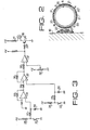
- One of the speed detectors 14, 15 is shown in Figure 2.
- a number of permanent magnets 20 are circumferentially secured on the propeller shaft 8 (or on the shaft 11). Magnets 20 are separated from each other by synthetic resin 21 secured on the shaft.
- a reed switch 22 is provided on a support 19 formed on the body 1 and is positioned in the vicinity of the magnets 20 with a slight gap.
- a second reed switch is similarly provided adjacent the magnets on shaft 11.
- the reed switch for the front-wheel speed detector 15 is indicated at 23 and is connected to a voltage supply through a resistor 25.
- the reed switch 22 for the rear-wheel speed detector 14 and a resistor 26 are connected in series to the voltage supply.
- a first integrator comprising a resistor 27 and a capacitor 28 is connected to the resistor 25 and its output is connected to a non-inverting input of an operational amplifier 31.
- a second integrator comprisi.ng a resistor 29 and capacitor 30 is connected to the resistor 26 and to non-inverting input of an operational amplifier 32.
- the output of the operational amplifier 31 is connected to the inverting input thereof through a resistor 33 and to the inverting input of the operational amplifier 32 through a resistor 34.
- the output of the operational amplifier 32 is connected to the input thereof through . a resistor 35 and to non-inverting input of a comparator 37 through a resistor 36.
- the inverting input of the comparator 37 is connected to ground through a variable resistor 38.
- the output of the comparator 37 is connected to the base of a transistor 40 through a resistor 39.
- the lamp 18 and a resistor 41 are connected in series to the collector of the transistor 40.
- engine 4 drives front wheels 2 through the gear box 5, shaft 11 and front axles 13.
- the speeds of front and rear wheels are detected by speed detectors 14 and 15.
- the reed switch 22 or 23 is periodically closed by magnets 20 at a repetition rate in accordance with the speed of the wheels. Accordingly, the output of the associated integrator 27, 28 or 29, 30 varies in dependency on the speed of the wheels.
- the output at the capacitor 28 is applied to the operational amplifier 32 through the amplifier 31 and the output at the capacitor 30 is also applied to the operational amplifier 32, where the speed of the front wheels is compared with that of the rear wheels.
- the output of the operational amplifier 32 is applied to the comparator for comparing it with a reference voltage by the resistor 38.
- the system of the present invention indicates the necessity of the four-wheel driving.
- the operator can drive the vehicle without special attention to the road condition.
- the output of the comparator 37 may be utilised to operate the clutch automatically to f change from two-wheel to four-wheel drive.
Landscapes
- Engineering & Computer Science (AREA)
- Chemical & Material Sciences (AREA)
- Combustion & Propulsion (AREA)
- Transportation (AREA)
- Mechanical Engineering (AREA)
- Arrangement And Mounting Of Devices That Control Transmission Of Motive Force (AREA)
- Arrangement And Driving Of Transmission Devices (AREA)
Abstract
An internal combustion engine comprises a transmission for transmitting a power from the engine to two main driving wheels, a clutch for selectively transmitting the power to another two wheels, a selection lever for engaging said clutch, compares the speeds of the two pairs of wheels and gives a signal when the wheel slippage occurs, to warn the driver that four-wheel drive should be engaged. The indication system comprises speed detectors (23,27,28 and 22, 29, 30) which detects the speeds of the main driving wheels and the other two wheels. An electric circuit (32-38) compares the speeds and illuminates a warning lamp (18) when the difference between the speeds exceeds a predetermined level, whereby slippage of the main driving two-wheel is detected.
Description
- The present invention relates to a system for indicating the necessity to engage four-wheel drive on a 2/4--wheel drive vehicle.
- In a 2/4-wheel drive vehicle, a clutch device is provided to select either two-wheel drive or four-wheel drive. The clutch device is engaged by the manual operation of a selection lever.
- The vehicle is advantageously driven with four-wheel drive engaged in slippery conditions such as are encountered in snow and ice. In a conventional four-wheel drive vehicle, the operator manipulates the selection lever when he judges the necessity of the four-wheel drive. The judgement of the operator may not always be right and moreover the operator must take trouble to judge the road conditions.
- An object of the present invention is to provide a system for a 2/4-wheel drive vehicle which automatically gives a signal for operating the clutch selection lever to change the transmission from two-wheel drive to four-wheel drive.
- According to the present invention, an indication for a 2/4-wheel drive vehicle which has an internal combustion engine, a transmission for transmitting power from the engine to two main driving wheels, a clutch for selectively transmitting the power additionally to another two wheels, and selection means for engaging the clutch, comprises means for selecting slippage of the two main driving wheels and an electric circuit responsive to a signal from the detecting means for indicating when slippage occurs.
- The indicating circuit may illuminate a warning light, or may operate an automatic control for engaging 4-wheel drive.
- Embodiments of the invention will now be described with reference to the accompanying drawings in which:
- Figure 1 is a plan view showing a vehicle having a 2/4-wheel driving system;
- Figure 2 is a sectional view showing a speed detector; and
- Figure 3 is an indication system used on the vehicle.
- Referring to Figure 1, reference numeral 1 designates a body of a vehicle, 2 are front wheels and 3 are rear wheels. An engine 4 is mounted on the body 1 at the front. The power of the engine is transmitted through a gear box 5, either to the front wheels or to both the front and the rear wheels by selective engagement of a clutch in the transmission 5. Gear change is effected by means of a gear lever 6. The clutch in the gear box 5 is engaged by operating a
shift lever 7 in order to transmit power additionally to therear wheels 3. The output of the gear box 5 is transmitted to the front wheels 2 through a shaft 11, afront differential 12 andfront axles 13. The power transmission to therear wheels 3 comprises a propeller shaft 8 extending from the gear box 5, a rear differential 9 andrear axles 10. - In order to detect the rotational speeds of the front and
rear wheels 2, 3, a front-wheel speed detector 15 is mounted adjacent to the shaft 11 and a rear-wheel speed detector 14 is mounted adjacent to the propeller shaft 8. The outputs of the twospeed detectors 14 and 15 are connected to ajudgement device 16, the output of which is connected to alamp 18 on aninstrument panel 17 to give a warning of the necessity to engage four-wheel drive. - One of the
speed detectors 14, 15 is shown in Figure 2. A number ofpermanent magnets 20 are circumferentially secured on the propeller shaft 8 (or on the shaft 11).Magnets 20 are separated from each other bysynthetic resin 21 secured on the shaft. For the rear speed detector, areed switch 22 is provided on asupport 19 formed on the body 1 and is positioned in the vicinity of themagnets 20 with a slight gap. A second reed switch is similarly provided adjacent the magnets on shaft 11. - Referring to Figure 3, the reed switch for the front-
wheel speed detector 15 is indicated at 23 and is connected to a voltage supply through aresistor 25. Thereed switch 22 for the rear-wheel speed detector 14 and aresistor 26 are connected in series to the voltage supply. A first integrator comprising a resistor 27 and acapacitor 28 is connected to theresistor 25 and its output is connected to a non-inverting input of anoperational amplifier 31. Similarly, a second integrator comprisi.ng aresistor 29 andcapacitor 30 is connected to theresistor 26 and to non-inverting input of an operational amplifier 32. The output of theoperational amplifier 31 is connected to the inverting input thereof through aresistor 33 and to the inverting input of the operational amplifier 32 through aresistor 34. The output of the operational amplifier 32 is connected to the input thereof through . aresistor 35 and to non-inverting input of acomparator 37 through aresistor 36. The inverting input of thecomparator 37 is connected to ground through a variable resistor 38. The output of thecomparator 37 is connected to the base of atransistor 40 through aresistor 39. Thelamp 18 and aresistor 41 are connected in series to the collector of the transistor 40., - During two-wheel drive, engine 4 drives front wheels 2 through the gear box 5, shaft 11 and
front axles 13. The speeds of front and rear wheels are detected byspeed detectors 14 and 15. In each speed detector, thereed switch magnets 20 at a repetition rate in accordance with the speed of the wheels. Accordingly, the output of the associatedintegrator capacitor 28 is applied to the operational amplifier 32 through theamplifier 31 and the output at thecapacitor 30 is also applied to the operational amplifier 32, where the speed of the front wheels is compared with that of the rear wheels. The output of the operational amplifier 32 is applied to the comparator for comparing it with a reference voltage by the resistor 38. When the front wheels slip, their speed increases relative to the speed of the undriven rear wheels and the output voltage of the operational amplifier 32 increases, causing the output voltage of thecomparator 37 to increase. When the output of thecomparator 37 exceeds a predetermined level, determined by variable resistor 38, thetransistor 40 is turned on, and alamp 18 is illuminated. Thus, the need to the four-wheel drive is indicated by thelamp 18.. When theselection lever 7 is manipulated by the operator in response to the warning, the two-wheel drive through front wheels 2 is changed to four-wheel drive through the front and rear wheels. - From the foregoing, it will be understood that the system of the present invention indicates the necessity of the four-wheel driving. Thus, in accordance with the system, the operator can drive the vehicle without special attention to the road condition. If desired the output of the
comparator 37 may be utilised to operate the clutch automatically to f change from two-wheel to four-wheel drive.
Claims (3)
1. An indication system for a 2/4-wheel drive vehicle, which has an internal combustion engine (4), a transmission (5) for transmitting power from the engine to two main driving wheels (2), a clutch for selectively transmitting the power additionally to another two wheels, and selection means (7) for engaging the clutch, the indication system comprising means (22-38) for detecting slippage of the two main driving wheels (2), and an electric circuit (18, 39-41) responsive to a signal from the detecting means for indicating when slippage occurs.
2. An indication system for a 2/4-wheel drive vehicle in accordance with claim 1, wherein the slippage detecting means comprises a first speed detector (23, 27, 28) for detecting the speed of the main driving wheels (2), a second speed detector (22, 29, 30) for detecting the speed of the other two wheels (3), and a comparison circuit (32, 37, 38) for comparing the two speeds and for producing a signal for operating the indicating circuit when the difference between the speeds exceeds a predetermined level.
3. An indication system for a 2/4-wheel drive vehicle in accordance with claim 1 or claim 2, in which the indicating circuit includes a lamp (18) which is illuminated when slippage occurs as a warning that four-wheel drive should be engaged.
Applications Claiming Priority (2)
| Application Number | Priority Date | Filing Date | Title |
|---|---|---|---|
| JP55158352A JPS5780926A (en) | 1980-11-11 | 1980-11-11 | Transfer directing device of four-wheel driving car |
| JP158352/80 | 1980-11-11 |
Publications (1)
| Publication Number | Publication Date |
|---|---|
| EP0052012A1 true EP0052012A1 (en) | 1982-05-19 |
Family
ID=15669770
Family Applications (1)
| Application Number | Title | Priority Date | Filing Date |
|---|---|---|---|
| EP81305330A Withdrawn EP0052012A1 (en) | 1980-11-11 | 1981-11-10 | Indication system for a four-wheel drive vehicle |
Country Status (4)
| Country | Link |
|---|---|
| US (1) | US4433748A (en) |
| EP (1) | EP0052012A1 (en) |
| JP (1) | JPS5780926A (en) |
| AU (1) | AU531451B2 (en) |
Cited By (4)
| Publication number | Priority date | Publication date | Assignee | Title |
|---|---|---|---|---|
| FR2520680A1 (en) * | 1982-01-29 | 1983-08-05 | Fuji Heavy Ind Ltd | TRANSMISSION SYSTEM FOR A FOUR-WHEELED VEHICLE |
| FR2552034A1 (en) * | 1983-09-19 | 1985-03-22 | Fuji Heavy Ind Ltd | DEVICE FOR CONTROLLING A TRANSMISSION OF A FOUR-DRIVE VEHICLE |
| EP0208173A1 (en) * | 1985-06-17 | 1987-01-14 | Mazda Motor Corporation | Four-wheel steering system for vehicle |
| EP0187117A3 (en) * | 1984-12-24 | 1987-03-04 | United Tech Elect Systems | Electric shift actuator for vehicle transfer case |
Families Citing this family (14)
| Publication number | Priority date | Publication date | Assignee | Title |
|---|---|---|---|---|
| JPS58177722A (en) * | 1982-04-09 | 1983-10-18 | Fuji Heavy Ind Ltd | Selective controller of 4-wheel driven car |
| JPS58180324A (en) * | 1982-04-14 | 1983-10-21 | Fuji Heavy Ind Ltd | Selective controller of 4-wheel driven car |
| JPS59109430A (en) * | 1982-12-15 | 1984-06-25 | Fuji Heavy Ind Ltd | Switch controller for part time four wheel drive car |
| JPS59109431A (en) * | 1982-12-16 | 1984-06-25 | Fuji Heavy Ind Ltd | Switch controller for four wheel drive car |
| JPS59216732A (en) * | 1983-05-23 | 1984-12-06 | Nissan Motor Co Ltd | Four-wheel-drive vehicle |
| JPS60156036U (en) * | 1984-03-28 | 1985-10-17 | アイシン精機株式会社 | Power distribution device control device |
| ATE30877T1 (en) * | 1984-05-25 | 1987-12-15 | Deere & Co | FOUR-WHEEL DRIVE VEHICLE. |
| JPS60263751A (en) * | 1984-06-13 | 1985-12-27 | Aisin Warner Ltd | Four-wheel drive transfer display device of four-wheel drive car |
| JPS60263753A (en) * | 1984-06-13 | 1985-12-27 | Aisin Warner Ltd | Control device of four-wheel drive automatic speed changer |
| JPS6142330U (en) * | 1984-08-22 | 1986-03-18 | 三菱自動車工業株式会社 | four wheel drive vehicle |
| JPS6141038U (en) * | 1984-08-22 | 1986-03-15 | 三菱自動車工業株式会社 | four wheel drive vehicle |
| US4792010A (en) * | 1986-07-11 | 1988-12-20 | 501 Kubota, Ltd. | Four wheel drive vehicle |
| US4854414A (en) * | 1986-07-29 | 1989-08-08 | Toyota Jidosha Kabushiki Kaisha | Electric control apparatus for transfer device in part-time four-wheel drive vehicle |
| US4937750A (en) * | 1987-12-23 | 1990-06-26 | Dana Corporation | Electronic control for vehicle four wheel drive system |
Citations (6)
| Publication number | Priority date | Publication date | Assignee | Title |
|---|---|---|---|---|
| US3484009A (en) * | 1968-04-22 | 1969-12-16 | Caterpillar Tractor Co | Automatic shift mechanism for two wheel-four wheel drive vehicle |
| US3845671A (en) * | 1973-02-12 | 1974-11-05 | Chrysler Corp | Full time slip controlled four wheel drive |
| FR2311961A1 (en) * | 1975-05-22 | 1976-12-17 | Eaton Corp | MULTIPLE DRIVE AXLES ASSEMBLY |
| JPS55148622A (en) * | 1979-05-09 | 1980-11-19 | Kubota Ltd | Working vehicle |
| JPS55152624A (en) * | 1979-05-16 | 1980-11-28 | Kubota Ltd | Work vehicle |
| US4236595A (en) * | 1979-08-17 | 1980-12-02 | Parno Corp. | Auxiliary drive system |
Family Cites Families (3)
| Publication number | Priority date | Publication date | Assignee | Title |
|---|---|---|---|---|
| DE2023346A1 (en) | 1970-05-13 | 1971-12-02 | Bosch Gmbh Robert | Electronic slip measuring device |
| US4086563A (en) | 1975-07-10 | 1978-04-25 | Dickey-John Corporation | Wheel slippage monitor |
| JPS5572420A (en) | 1978-11-24 | 1980-05-31 | Aisin Warner Ltd | Four-wheel driving gear |
-
1980
- 1980-11-11 JP JP55158352A patent/JPS5780926A/en active Pending
-
1981
- 1981-11-10 EP EP81305330A patent/EP0052012A1/en not_active Withdrawn
- 1981-11-11 AU AU77362/81A patent/AU531451B2/en not_active Ceased
- 1981-11-12 US US06/320,776 patent/US4433748A/en not_active Expired - Lifetime
Patent Citations (6)
| Publication number | Priority date | Publication date | Assignee | Title |
|---|---|---|---|---|
| US3484009A (en) * | 1968-04-22 | 1969-12-16 | Caterpillar Tractor Co | Automatic shift mechanism for two wheel-four wheel drive vehicle |
| US3845671A (en) * | 1973-02-12 | 1974-11-05 | Chrysler Corp | Full time slip controlled four wheel drive |
| FR2311961A1 (en) * | 1975-05-22 | 1976-12-17 | Eaton Corp | MULTIPLE DRIVE AXLES ASSEMBLY |
| JPS55148622A (en) * | 1979-05-09 | 1980-11-19 | Kubota Ltd | Working vehicle |
| JPS55152624A (en) * | 1979-05-16 | 1980-11-28 | Kubota Ltd | Work vehicle |
| US4236595A (en) * | 1979-08-17 | 1980-12-02 | Parno Corp. | Auxiliary drive system |
Cited By (4)
| Publication number | Priority date | Publication date | Assignee | Title |
|---|---|---|---|---|
| FR2520680A1 (en) * | 1982-01-29 | 1983-08-05 | Fuji Heavy Ind Ltd | TRANSMISSION SYSTEM FOR A FOUR-WHEELED VEHICLE |
| FR2552034A1 (en) * | 1983-09-19 | 1985-03-22 | Fuji Heavy Ind Ltd | DEVICE FOR CONTROLLING A TRANSMISSION OF A FOUR-DRIVE VEHICLE |
| EP0187117A3 (en) * | 1984-12-24 | 1987-03-04 | United Tech Elect Systems | Electric shift actuator for vehicle transfer case |
| EP0208173A1 (en) * | 1985-06-17 | 1987-01-14 | Mazda Motor Corporation | Four-wheel steering system for vehicle |
Also Published As
| Publication number | Publication date |
|---|---|
| AU531451B2 (en) | 1983-08-25 |
| US4433748A (en) | 1984-02-28 |
| AU7736281A (en) | 1982-05-20 |
| JPS5780926A (en) | 1982-05-20 |
Similar Documents
| Publication | Publication Date | Title |
|---|---|---|
| EP0052012A1 (en) | Indication system for a four-wheel drive vehicle | |
| KR100301741B1 (en) | Torque Distribution Device of Vehicle | |
| US5844411A (en) | Diagnostic detection for hall effect digital gear tooth sensors and related method | |
| KR100243892B1 (en) | Method/system for determination of gross combined weight of vehicles equipped with electronic data links | |
| FI79980C (en) | Locking system for motor vehicles with four-wheel drive | |
| EP0396323B1 (en) | Torque distribution control system for a four-wheel drive motor vehicle | |
| EP0110857B1 (en) | A self-teaching device for signalling to the driver of a vehicle that a gear change is indicated | |
| KR950017338A (en) | On demand vehicle diive system | |
| US5562192A (en) | Electronic clutch control mechanism for a vehicle transmission | |
| CN101158393A (en) | Automated inter-axle differential lock sensor configuration and calibration method | |
| KR940000297A (en) | Vehicle drive system | |
| US6213242B1 (en) | Four wheel drive system having torque distribution control responsive to throttle position, speed and selected range | |
| JPS6323934B2 (en) | ||
| US4714127A (en) | Control apparatus for a vehicle with disengageable four-wheel drive | |
| US3420328A (en) | Electronic shift indicator | |
| ES2049967T3 (en) | A METHOD AND A SYSTEM TO CONTROL THE TRACTION IN MOTOR VEHICLES WITH MECHANICAL GEARBOXES. | |
| US4718515A (en) | Control device for a vehicle with disengageable four-wheel drive | |
| EP0053033B1 (en) | Slip indicating system for a four-wheel drive vehicle | |
| KR950010221B1 (en) | Control system for vehicle with differential restricting device | |
| EP0282187A1 (en) | Power transmitting system for a four-wheel drive vehicle | |
| US4947325A (en) | Diagnostic system for rotational speed sensors in drive train of four wheels drive vehicle having central differential device | |
| JPS63212130A (en) | Fail-safe device for four-wheel-drive automobile | |
| US4830136A (en) | Four-wheel drive motor vehicle | |
| JPS6490825A (en) | Power transmission changing device of four-wheel-drive vehicle | |
| JPS6490824A (en) | Power transmission changing device of four-wheel-drive vehicle |
Legal Events
| Date | Code | Title | Description |
|---|---|---|---|
| PUAI | Public reference made under article 153(3) epc to a published international application that has entered the european phase |
Free format text: ORIGINAL CODE: 0009012 |
|
| 17P | Request for examination filed |
Effective date: 19811204 |
|
| AK | Designated contracting states |
Designated state(s): CH DE FR GB SE |
|
| DET | De: translation of patent claims | ||
| STAA | Information on the status of an ep patent application or granted ep patent |
Free format text: STATUS: THE APPLICATION IS DEEMED TO BE WITHDRAWN |
|
| 18D | Application deemed to be withdrawn |
Effective date: 19840628 |
|
| RIN1 | Information on inventor provided before grant (corrected) |
Inventor name: SATOH, TETSUO Inventor name: OHGAMI, MASAAKI Inventor name: OGATA, SHOJI |