EP0051908A1 - A device for coupling or decoupling screw-threaded components - Google Patents
A device for coupling or decoupling screw-threaded components Download PDFInfo
- Publication number
- EP0051908A1 EP0051908A1 EP81301371A EP81301371A EP0051908A1 EP 0051908 A1 EP0051908 A1 EP 0051908A1 EP 81301371 A EP81301371 A EP 81301371A EP 81301371 A EP81301371 A EP 81301371A EP 0051908 A1 EP0051908 A1 EP 0051908A1
- Authority
- EP
- European Patent Office
- Prior art keywords
- component
- demountable
- torque
- decoupling
- coupling
- Prior art date
- Legal status (The legal status is an assumption and is not a legal conclusion. Google has not performed a legal analysis and makes no representation as to the accuracy of the status listed.)
- Granted
Links
Images

Classifications
-
- B—PERFORMING OPERATIONS; TRANSPORTING
- B25—HAND TOOLS; PORTABLE POWER-DRIVEN TOOLS; MANIPULATORS
- B25B—TOOLS OR BENCH DEVICES NOT OTHERWISE PROVIDED FOR, FOR FASTENING, CONNECTING, DISENGAGING OR HOLDING
- B25B17/00—Hand-driven gear-operated wrenches or screwdrivers
-
- B—PERFORMING OPERATIONS; TRANSPORTING
- B25—HAND TOOLS; PORTABLE POWER-DRIVEN TOOLS; MANIPULATORS
- B25B—TOOLS OR BENCH DEVICES NOT OTHERWISE PROVIDED FOR, FOR FASTENING, CONNECTING, DISENGAGING OR HOLDING
- B25B13/00—Spanners; Wrenches
- B25B13/48—Spanners; Wrenches for special purposes
- B25B13/50—Spanners; Wrenches for special purposes for operating on work of special profile, e.g. pipes
- B25B13/5008—Spanners; Wrenches for special purposes for operating on work of special profile, e.g. pipes for operating on pipes or cylindrical objects
- B25B13/5016—Spanners; Wrenches for special purposes for operating on work of special profile, e.g. pipes for operating on pipes or cylindrical objects by externally gripping the pipe
Definitions
- This invention relates to devices for assembling and disassembling components coupled by means of a screw thread. It finds particular application in the mountings of fittings on and their removal from service pipes such as gas pipes without the application of extraneous torque to the pipe and the consequent disturbance of other screw-threaded joints.
- a device for coupling a first component to a second component by means of a screw thread or decoupling a first such component from a second such component comprising restraining means, first demountable clamping means rigidly attachable to said restraining means and adapted to clamp said first component, and second demountable clamping means also rigidly attachable to said restraining means wherein said second demountable clamping means comprises retaining means and gripping means for said second component rotatable with respect to said retaining means to apply a torque to said second component.
- FIG. 1 shows a tool 1 mounted on a pipe 2 ready to unscrew a gas cock 3 therefrom.
- the tool comprises a first clamping means 4 which grips the pipe and a second clamping means 5 which grips the gas cock, both clamping means being mounted on restraining means consisting of a pair of rods 6,7.
- the first clamping means 4 ( Figure 5) comprises a pair of retaining arms 8,9, coupled by a hinge 10. Demountably held by the arms are jaw retaining members 11,12 to which are attached jaws 13-15 which grip the pipe. Alternative sets of jaws may be applied to accommodate different pipe sizes.
- the arms are urged together by means of an assembly bolt 16 which causes the jaws to grip the pipe firmly and couple it securely to the rods 6,7.
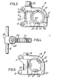
- the second clamping means 5 ( Figures 3,4) also has two retaining arms 17,18 coupled by a hinge 19. These arms are grooved and act as a guide to a split gripping member 20,21 having indentations 22 to grip a fitting such as a gas cock.
- the outer periphery of the gripping member 20,21 is toothed and cooperates with a worm 23 mounted on an axle 24.
- the axle is rotatable by means of a head 25 to which a spanner or the like may be applied. With a right-hand thread, rotating the axle clockwise causes the fitting to be clamped and a releasing torque to be applied thereto. Anticlockwise rotation causes the axle to be withdrawn from its guide.
- a torque-limiting device 26 When tightening a fitting, a torque-limiting device 26 may advantageously be used.
- a device of the type described may conveniently be used in inaccessible positions such as the corners of rooms or in cupboards.
- Different clamping means may be fitted to accommodate different pipe sizes and variations in fittings. Its use is not limited to unscrewing fittings from service pipes; it may, for example, be used in like manner to assemble or disassemble compression joints or cable glands.
Landscapes
- Engineering & Computer Science (AREA)
- Mechanical Engineering (AREA)
- Valve Housings (AREA)
- Mutual Connection Of Rods And Tubes (AREA)
- Quick-Acting Or Multi-Walled Pipe Joints (AREA)
Abstract
Description
- This invention relates to devices for assembling and disassembling components coupled by means of a screw thread. It finds particular application in the mountings of fittings on and their removal from service pipes such as gas pipes without the application of extraneous torque to the pipe and the consequent disturbance of other screw-threaded joints.
- During the servicing of fittings attached to service pipes, particularly gas meter control cocks, a frequent problem is that other joints in the pipes are disturbed and leaks may occur. Conventionally, such fittings are disassembled and dissembled using two pairs of pipe wrenches, one of which holds the pipe whilst the other holds the fitting. If the joint is particularly tight, the wrench holding the pipe may slip and a fitting in the supply pipe may become loose causing gas leakage.
- In order to overcome this problem a tool has been devised having an independent restraining body to which the service pipe is clamped whilst torque is applied to the fitting.
- According to the present invention there is provided a device for coupling a first component to a second component by means of a screw thread or decoupling a first such component from a second such component, comprising restraining means, first demountable clamping means rigidly attachable to said restraining means and adapted to clamp said first component, and second demountable clamping means also rigidly attachable to said restraining means wherein said second demountable clamping means comprises retaining means and gripping means for said second component rotatable with respect to said retaining means to apply a torque to said second component.
- An embodiment of the invention will now be described by way of example with reference to the accompanying drawings in which:-
- Figure 1 shows a device in accordance with an embodiment of the invention mounted to disassemble a gas cock from a service pipe
- Figure 2 shows a device mounted to assemble a gas cock on a service pipe
- Figure 3 is a view of a part of the device of Figure 1
- Figure 4 is a section along the line AA' of Figure 3; and
- Figure 5 is a view corresponding to that of Figure 3 of the pipe clamping means mounted to assemble a gas cock on a service pipe.
- Referring now to Figure 1, this shows a tool 1 mounted on a
pipe 2 ready to unscrew a gas cock 3 therefrom. The tool comprises a first clamping means 4 which grips the pipe and a second clamping means 5 which grips the gas cock, both clamping means being mounted on restraining means consisting of a pair ofrods 6,7. The first clamping means 4 (Figure 5) comprises a pair of retainingarms hinge 10. Demountably held by the arms are jaw retainingmembers assembly bolt 16 which causes the jaws to grip the pipe firmly and couple it securely to therods 6,7. - The second clamping means 5 (Figures 3,4) also has two retaining
arms hinge 19. These arms are grooved and act as a guide to a split grippingmember indentations 22 to grip a fitting such as a gas cock. The outer periphery of thegripping member worm 23 mounted on anaxle 24. The axle is rotatable by means of ahead 25 to which a spanner or the like may be applied. With a right-hand thread, rotating the axle clockwise causes the fitting to be clamped and a releasing torque to be applied thereto. Anticlockwise rotation causes the axle to be withdrawn from its guide. - In order to fit a replacement valve, the tool is assembled the opposite way round as shown in Figure 2.
- When tightening a fitting, a torque-limiting
device 26 may advantageously be used. - A device of the type described may conveniently be used in inaccessible positions such as the corners of rooms or in cupboards. Different clamping means may be fitted to accommodate different pipe sizes and variations in fittings. Its use is not limited to unscrewing fittings from service pipes; it may, for example, be used in like manner to assemble or disassemble compression joints or cable glands.
Claims (9)
Applications Claiming Priority (2)
| Application Number | Priority Date | Filing Date | Title |
|---|---|---|---|
| GB8036117A GB2086784B (en) | 1980-11-11 | 1980-11-11 | Pipe fitting screwing/unscrewing tool |
| GB8036117 | 1980-11-11 |
Publications (2)
| Publication Number | Publication Date |
|---|---|
| EP0051908A1 true EP0051908A1 (en) | 1982-05-19 |
| EP0051908B1 EP0051908B1 (en) | 1984-09-12 |
Family
ID=10517212
Family Applications (1)
| Application Number | Title | Priority Date | Filing Date |
|---|---|---|---|
| EP81301371A Expired EP0051908B1 (en) | 1980-11-11 | 1981-03-30 | A device for coupling or decoupling screw-threaded components |
Country Status (4)
| Country | Link |
|---|---|
| US (1) | US4380940A (en) |
| EP (1) | EP0051908B1 (en) |
| DE (1) | DE3165929D1 (en) |
| GB (1) | GB2086784B (en) |
Cited By (1)
| Publication number | Priority date | Publication date | Assignee | Title |
|---|---|---|---|---|
| DE202020101932U1 (en) * | 2020-04-08 | 2020-11-16 | GEDORE Holding GmbH | Tool for assembling and / or disassembling a rod screwed at both ends |
Families Citing this family (5)
| Publication number | Priority date | Publication date | Assignee | Title |
|---|---|---|---|---|
| DE8901141U1 (en) * | 1989-02-02 | 1989-03-23 | Matthäus, Heinz Dieter, 4620 Castrop-Rauxel | Device for arc metal spraying |
| AU5843596A (en) * | 1995-12-18 | 1997-07-14 | Patrick Wathieu | Paper cutter for variable format |
| FR2881369B1 (en) * | 2005-01-28 | 2008-07-25 | Lopata Sarl Ets | TOOL FOR MOUNTING AND DISASSEMBLING A CHUCK FOR COLD ROLLING |
| USD968491S1 (en) * | 2019-10-21 | 2022-11-01 | Aimco | High torque tool |
| IT202300017208A1 (en) * | 2023-08-11 | 2025-02-11 | C M M S R L | SCREWING DEVICE AND RELATED PROCEDURE |
Citations (8)
| Publication number | Priority date | Publication date | Assignee | Title |
|---|---|---|---|---|
| US1447744A (en) * | 1921-02-16 | 1923-03-06 | Nat Supply Co | Machine pipe wrench |
| US1629895A (en) * | 1925-11-18 | 1927-05-24 | Marks J Tully | Double wrench |
| US2757523A (en) * | 1953-12-07 | 1956-08-07 | Reed Roller Bit Co | Torque controlling device |
| US3097551A (en) * | 1963-07-16 | schmitt | ||
| US3122952A (en) * | 1964-03-03 | Wrench winch | ||
| US3564955A (en) * | 1969-02-05 | 1971-02-23 | Clarence F Batchelder | High torque wrench assembly |
| US3709072A (en) * | 1971-04-15 | 1973-01-09 | W Rogers | Motor driven pipe wrench |
| US3902385A (en) * | 1974-03-14 | 1975-09-02 | Varco Int | Pipe joint make-up or break-out tool |
Family Cites Families (5)
| Publication number | Priority date | Publication date | Assignee | Title |
|---|---|---|---|---|
| US1808959A (en) * | 1929-09-07 | 1931-06-09 | Charles H Lane | Tong |
| US2450967A (en) * | 1947-01-27 | 1948-10-12 | Keiser John | Combined pipe wrench and vise |
| JPS5135277B2 (en) * | 1973-07-30 | 1976-10-01 | ||
| US4215599A (en) * | 1978-08-28 | 1980-08-05 | Khartli, Inc. | Torque multiplier assembly |
| US4309923A (en) * | 1980-06-23 | 1982-01-12 | N-S-W Corporation | Power tool for torquing enclosed connectors |
-
1980
- 1980-11-11 GB GB8036117A patent/GB2086784B/en not_active Expired
-
1981
- 1981-03-30 EP EP81301371A patent/EP0051908B1/en not_active Expired
- 1981-03-30 DE DE8181301371T patent/DE3165929D1/en not_active Expired
- 1981-04-03 US US06/250,770 patent/US4380940A/en not_active Expired - Lifetime
Patent Citations (8)
| Publication number | Priority date | Publication date | Assignee | Title |
|---|---|---|---|---|
| US3097551A (en) * | 1963-07-16 | schmitt | ||
| US3122952A (en) * | 1964-03-03 | Wrench winch | ||
| US1447744A (en) * | 1921-02-16 | 1923-03-06 | Nat Supply Co | Machine pipe wrench |
| US1629895A (en) * | 1925-11-18 | 1927-05-24 | Marks J Tully | Double wrench |
| US2757523A (en) * | 1953-12-07 | 1956-08-07 | Reed Roller Bit Co | Torque controlling device |
| US3564955A (en) * | 1969-02-05 | 1971-02-23 | Clarence F Batchelder | High torque wrench assembly |
| US3709072A (en) * | 1971-04-15 | 1973-01-09 | W Rogers | Motor driven pipe wrench |
| US3902385A (en) * | 1974-03-14 | 1975-09-02 | Varco Int | Pipe joint make-up or break-out tool |
Non-Patent Citations (1)
| Title |
|---|
| "Soviet Inventions Illustrated", Week B 06, 21 March 1979, Section Q 49 & SU-A-599039 * |
Cited By (1)
| Publication number | Priority date | Publication date | Assignee | Title |
|---|---|---|---|---|
| DE202020101932U1 (en) * | 2020-04-08 | 2020-11-16 | GEDORE Holding GmbH | Tool for assembling and / or disassembling a rod screwed at both ends |
Also Published As
| Publication number | Publication date |
|---|---|
| US4380940A (en) | 1983-04-26 |
| EP0051908B1 (en) | 1984-09-12 |
| GB2086784A (en) | 1982-05-19 |
| GB2086784B (en) | 1984-09-05 |
| DE3165929D1 (en) | 1984-10-18 |
Similar Documents
| Publication | Publication Date | Title |
|---|---|---|
| US4393583A (en) | Anti-torque connection apparatus and method for using | |
| CA2178769C (en) | Pipe junction holder with a novel torque-limiting device | |
| US5490693A (en) | Tube coupling locking device | |
| US5263515A (en) | Device for repairing a tube | |
| US5222768A (en) | Fluid line nut locking device | |
| SE441954B (en) | Pipe coupling | |
| US5007312A (en) | Wrench for metal tubing connectors | |
| US4380940A (en) | No torque tool | |
| US6276237B1 (en) | Coaxial socket | |
| CN111868430A (en) | Locking device for pipe joint and valve joint | |
| US5947527A (en) | Junction holder for connecting pipes with mechanical joints | |
| EP0786617A2 (en) | Tube coupling locking device | |
| US3527478A (en) | Conduit coupling manipulator | |
| US5466014A (en) | Clamp for line fitting | |
| EP0650560B1 (en) | Dynamometric screw or nut | |
| JPH0160714B2 (en) | ||
| US7278340B2 (en) | Apparatus for removing and installing a tie rod | |
| US3447405A (en) | Fitting wrench | |
| JPH0211992A (en) | Piping clamp coupling for semiconductor manufacturing equipment | |
| US2807388A (en) | Valve clamp | |
| US20040183293A1 (en) | Pipe repair clamp installation tool | |
| US3774480A (en) | Apparatus for rotating valves on gas cylinders | |
| CN211517372U (en) | An intelligent fastening device for pipe fittings with limited space | |
| JPH0338531Y2 (en) | ||
| JP3785446B2 (en) | Pipe fitting pre-tightening jig |
Legal Events
| Date | Code | Title | Description |
|---|---|---|---|
| PUAI | Public reference made under article 153(3) epc to a published international application that has entered the european phase |
Free format text: ORIGINAL CODE: 0009012 |
|
| AK | Designated contracting states |
Designated state(s): BE DE FR IT NL |
|
| 17P | Request for examination filed |
Effective date: 19820420 |
|
| ITF | It: translation for a ep patent filed | ||
| GRAA | (expected) grant |
Free format text: ORIGINAL CODE: 0009210 |
|
| AK | Designated contracting states |
Designated state(s): BE DE FR IT NL |
|
| REF | Corresponds to: |
Ref document number: 3165929 Country of ref document: DE Date of ref document: 19841018 |
|
| ET | Fr: translation filed | ||
| BECH | Be: change of holder |
Free format text: 840912 *BRITISH GAS P.L.C. |
|
| PLBE | No opposition filed within time limit |
Free format text: ORIGINAL CODE: 0009261 |
|
| STAA | Information on the status of an ep patent application or granted ep patent |
Free format text: STATUS: NO OPPOSITION FILED WITHIN TIME LIMIT |
|
| 26N | No opposition filed | ||
| NLS | Nl: assignments of ep-patents |
Owner name: BRITISH GAS PLC TE LONDEN, GROOT-BRITTANNIE. |
|
| REG | Reference to a national code |
Ref country code: FR Ref legal event code: TP |
|
| ITTA | It: last paid annual fee | ||
| PGFP | Annual fee paid to national office [announced via postgrant information from national office to epo] |
Ref country code: FR Payment date: 19990208 Year of fee payment: 19 |
|
| PGFP | Annual fee paid to national office [announced via postgrant information from national office to epo] |
Ref country code: NL Payment date: 19990224 Year of fee payment: 19 |
|
| PGFP | Annual fee paid to national office [announced via postgrant information from national office to epo] |
Ref country code: DE Payment date: 19990226 Year of fee payment: 19 |
|
| PGFP | Annual fee paid to national office [announced via postgrant information from national office to epo] |
Ref country code: BE Payment date: 19990302 Year of fee payment: 19 |
|
| PG25 | Lapsed in a contracting state [announced via postgrant information from national office to epo] |
Ref country code: BE Free format text: LAPSE BECAUSE OF NON-PAYMENT OF DUE FEES Effective date: 20000331 |
|
| BERE | Be: lapsed |
Owner name: BG PUBLIC LIMITED COMPANY Effective date: 20000331 |
|
| PG25 | Lapsed in a contracting state [announced via postgrant information from national office to epo] |
Ref country code: NL Free format text: LAPSE BECAUSE OF NON-PAYMENT OF DUE FEES Effective date: 20001001 |
|
| PG25 | Lapsed in a contracting state [announced via postgrant information from national office to epo] |
Ref country code: FR Free format text: LAPSE BECAUSE OF NON-PAYMENT OF DUE FEES Effective date: 20001130 |
|
| NLV4 | Nl: lapsed or anulled due to non-payment of the annual fee |
Effective date: 20001001 |
|
| REG | Reference to a national code |
Ref country code: FR Ref legal event code: ST |
|
| PG25 | Lapsed in a contracting state [announced via postgrant information from national office to epo] |
Ref country code: DE Free format text: LAPSE BECAUSE OF NON-PAYMENT OF DUE FEES Effective date: 20010103 |