EP0051906A2 - Schaltung für ein Steuersystem eines Brennstoffbrenners - Google Patents
Schaltung für ein Steuersystem eines Brennstoffbrenners Download PDFInfo
- Publication number
- EP0051906A2 EP0051906A2 EP81300705A EP81300705A EP0051906A2 EP 0051906 A2 EP0051906 A2 EP 0051906A2 EP 81300705 A EP81300705 A EP 81300705A EP 81300705 A EP81300705 A EP 81300705A EP 0051906 A2 EP0051906 A2 EP 0051906A2
- Authority
- EP
- European Patent Office
- Prior art keywords
- circuit
- control system
- fuel burner
- burner control
- input
- Prior art date
- Legal status (The legal status is an assumption and is not a legal conclusion. Google has not performed a legal analysis and makes no representation as to the accuracy of the status listed.)
- Withdrawn
Links
Images

Classifications
-
- F—MECHANICAL ENGINEERING; LIGHTING; HEATING; WEAPONS; BLASTING
- F23—COMBUSTION APPARATUS; COMBUSTION PROCESSES
- F23N—REGULATING OR CONTROLLING COMBUSTION
- F23N1/00—Regulating fuel supply
- F23N1/002—Regulating fuel supply using electronic means
-
- F—MECHANICAL ENGINEERING; LIGHTING; HEATING; WEAPONS; BLASTING
- F23—COMBUSTION APPARATUS; COMBUSTION PROCESSES
- F23N—REGULATING OR CONTROLLING COMBUSTION
- F23N2223/00—Signal processing; Details thereof
- F23N2223/08—Microprocessor; Microcomputer
-
- F—MECHANICAL ENGINEERING; LIGHTING; HEATING; WEAPONS; BLASTING
- F23—COMBUSTION APPARATUS; COMBUSTION PROCESSES
- F23N—REGULATING OR CONTROLLING COMBUSTION
- F23N2227/00—Ignition or checking
- F23N2227/10—Sequential burner running
Definitions
- This invention relates to control units for fuel burners and, in particular, to circuits for control units incorporating microprocessors. It finds application in microprocessor based burner control units which may be used alone to control a single burner or in combination with other similar control units and a supervisory circuit to operate more than one burner.
- the present arrangement extends the principle of pulsing signals described in our earlier application by utilising a checking circuit which is sensitive to a prescribed frequency band. This ensures fail-safe operation in computerised control circuits should the clock frequency change by more than a predetermined amount.
- a circuit for a fuel burner control system comprising a source of input pulses having a repetition rate which is normally within a predetermined range, frequency sensitive diode pump circuit means sensitive to said pulses to produce an output having a direct current component which exceeds a predetermined threshold when the repetition rate of said input pulses is within said predetermined range but not when the repetition rate is outside said range and comparator circuit means adapted to deliver a control signal to said fuel control means when said direct current component exceeds said predetermined threshold.
- FIG. 1 shows a diode pump circuit which, conveniently, may be fed with a stream of pulses at its input A.
- a limiter resistor R prevents excessive input current flow.
- the pump circuit comprises a pair of sener diodes DZ1, DZ2 feeding two complementary switching transistors Tl, T2.
- the collectors of the switching transistors are coupled to two reservoir capacitors Cl, C2 which are in series with the drive coil of a relay which controls the load, which may be a fuel supply valve.
- Coupling diodes Dl, D2 direct the current flow to the reservoir capacitors according to which transistor is conducting.
- FIG. 2 shows the voltage across the two reservoir capacitors as the circuit input A is switched alternately high and low.
- the relay drive voltage which is the difference between the two capacitor voltages remains substantially constant so long as the switching continues at a predetermined rate, but the relay will drop out if the switching becomes too slow.
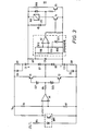
- FIG. 3 An embodiemnt suitable for mocroprocessor-based operation with a discrete pass band is shown in Figure 3.
- Pulses from a microprocessor output circuit pass by way of a resistor R5 and an optoelectronic isolator OPT to one input of a comparator Al, the other input of which is connected to a potential divider R6, R7 across the DC supply.
- the pulses are fed by way of the input resistor R4 and sener diodes DZ1, DZ2 to a pair of complementary switching transistors T1, T2 dividing a diode pump circuit comprising diodes D1, D2, capacitors C1, C2 and the impedance of the circuit connected at points X and Y.
- the pump circuit is loaded by either resistor R18 or relay coil RL1, the impedance of the resistor R18 being set approximately equal to that of the coil to maintain the circuit loading with the coil de-energised.
- a voltage comparator circuit R10, R11, R12, R13, DZ3, A2 is connected across the pump diodes Dl, D2 and senses the mean input voltage via the integrator R9, C3. As the input voltage to the comparator increases to a predetermined value, the voltage across one input is clamped by a zener diode DZ3. The voltage at the other, positive, input continues to rise until it is greater than that at the negative input.
- a relay driver transistor T4 coupled thereto conducts, energising the relay coil RL1 and turning off a further transistor T5 to prevent further conduction through R18 and thereby maintaining the same circuit loading.
- the state of the relay is indicated by a light emitting diode LED.
- the pulse frequency at which the diode pump circuit turns it on will be the same as the frequency at which it turns it off.
- an upper frequency cut-off point can be obtained by limiting the discharge time of the pump circuit capacitors C1, C2 by means of series-connected resistors R7, R8. Diodes D4, D5 are connected across these resistors.
- the capacitors Cl, C2 charge by way of the diodes and discharge by way of the resistors.
- the resistors R7, R8 also serve as current limiters, permitting the current to operate with lower rates transistors than would otherwise be required to drive the pump circuit.
Landscapes
- Engineering & Computer Science (AREA)
- Chemical & Material Sciences (AREA)
- Combustion & Propulsion (AREA)
- Mechanical Engineering (AREA)
- General Engineering & Computer Science (AREA)
- Feeding And Controlling Fuel (AREA)
- Regulation And Control Of Combustion (AREA)
Applications Claiming Priority (2)
| Application Number | Priority Date | Filing Date | Title |
|---|---|---|---|
| GB8035734A GB2087118B (en) | 1980-11-06 | 1980-11-06 | Fuel burner control system circuit |
| GB8035734 | 1980-11-06 |
Publications (2)
| Publication Number | Publication Date |
|---|---|
| EP0051906A2 true EP0051906A2 (de) | 1982-05-19 |
| EP0051906A3 EP0051906A3 (de) | 1983-02-09 |
Family
ID=10517138
Family Applications (1)
| Application Number | Title | Priority Date | Filing Date |
|---|---|---|---|
| EP19810300705 Withdrawn EP0051906A3 (de) | 1980-11-06 | 1981-02-19 | Schaltung für ein Steuersystem eines Brennstoffbrenners |
Country Status (9)
| Country | Link |
|---|---|
| US (1) | US4366391A (de) |
| EP (1) | EP0051906A3 (de) |
| JP (1) | JPS5780123A (de) |
| AU (1) | AU532724B2 (de) |
| CA (1) | CA1161520A (de) |
| CH (1) | CH641267A5 (de) |
| DK (1) | DK82981A (de) |
| GB (1) | GB2087118B (de) |
| ZA (1) | ZA811184B (de) |
Families Citing this family (3)
| Publication number | Priority date | Publication date | Assignee | Title |
|---|---|---|---|---|
| SE470527B (sv) * | 1992-11-18 | 1994-07-04 | Ericsson Telefon Ab L M | Metod och anordning för att detektera om en signal har en önskad på förhand fastställd frekvens eller ej |
| DE10157857C1 (de) * | 2001-11-26 | 2003-06-26 | Eberspaecher J Gmbh & Co | Sicherheitsvorrichtung für ein Fahrzeug-Zusatzheizgerät |
| WO2005121620A1 (ja) * | 2004-06-07 | 2005-12-22 | Yazaki Corporation | 電磁弁の駆動方法、電磁弁駆動装置及び電線着色装置 |
Family Cites Families (4)
| Publication number | Priority date | Publication date | Assignee | Title |
|---|---|---|---|---|
| US2747146A (en) * | 1952-02-12 | 1956-05-22 | Cook Electric Co | Frequency enseitive control apparatus |
| GB1002738A (en) * | 1961-06-07 | 1965-08-25 | Philips Electronic Associated | Improvements in or relating to devices, in particular safety devices, responsive to pulses |
| US3954383A (en) * | 1973-09-17 | 1976-05-04 | Electronics Corporation Of America | Burner control system |
| US3852606A (en) * | 1973-10-12 | 1974-12-03 | Honeywell Inc | Flame detection system utilizing a radiation coupling |
-
1980
- 1980-11-06 GB GB8035734A patent/GB2087118B/en not_active Expired
-
1981
- 1981-02-19 EP EP19810300705 patent/EP0051906A3/de not_active Withdrawn
- 1981-02-23 ZA ZA00811184A patent/ZA811184B/xx unknown
- 1981-02-24 DK DK82981A patent/DK82981A/da not_active Application Discontinuation
- 1981-02-24 US US06/237,766 patent/US4366391A/en not_active Expired - Fee Related
- 1981-02-24 CA CA000371570A patent/CA1161520A/en not_active Expired
- 1981-03-17 JP JP3859481A patent/JPS5780123A/ja active Pending
- 1981-03-23 AU AU68631/81A patent/AU532724B2/en not_active Ceased
- 1981-04-02 CH CH224181A patent/CH641267A5/fr not_active IP Right Cessation
Also Published As
| Publication number | Publication date |
|---|---|
| ZA811184B (en) | 1982-05-26 |
| GB2087118A (en) | 1982-05-19 |
| CA1161520A (en) | 1984-01-31 |
| EP0051906A3 (de) | 1983-02-09 |
| AU532724B2 (en) | 1983-10-13 |
| GB2087118B (en) | 1984-11-07 |
| JPS5780123A (en) | 1982-05-19 |
| DK82981A (da) | 1982-05-07 |
| AU6863181A (en) | 1982-05-13 |
| CH641267A5 (fr) | 1984-02-15 |
| US4366391A (en) | 1982-12-28 |
Similar Documents
| Publication | Publication Date | Title |
|---|---|---|
| US3417306A (en) | Regulated voltage capacitor discharge circuit | |
| US4525699A (en) | Electronic monitoring system with malfunction indicator | |
| US4481557A (en) | Electrostatic coating system | |
| US3419736A (en) | Externally controlled capacitor charging and discharging circuit | |
| US4558226A (en) | Voltage detecting circuit with hysteresis characteristic and high noise immunity | |
| US4536693A (en) | High-speed capacitor discharge circuit suitable for the protection of detonation devices | |
| US4926303A (en) | Control circuit for a switching DC to DC Power converter including a multi-turn control transformer | |
| US4366391A (en) | Fuel burner control system circuits | |
| US4246881A (en) | System for decreasing the power consumption in the output transistor of an ignition system | |
| GB1017065A (en) | Improvements relating to electrical control circuits | |
| GB1083743A (en) | Improvements in or relating to electrical circuitry for controlling or indicating physical conditions | |
| US4112318A (en) | Condition control system utilizing digital logic | |
| GB1212246A (en) | Improvements in or relating to combustion supervision systems | |
| GB1279010A (en) | Battery voltage regulating systems | |
| US3852606A (en) | Flame detection system utilizing a radiation coupling | |
| GB906675A (en) | Voltage control systems | |
| US4452220A (en) | Electronically controlled ignition system | |
| US4391262A (en) | Ignition system for an internal combustion engine | |
| US4030010A (en) | Time delay control circuit | |
| US3668515A (en) | Load control system employing silicon controlled rectifiers with overvoltage protection and compensation for line voltage fluctuations | |
| SU750459A1 (ru) | Электронное реле | |
| GB1017134A (en) | Generator voltage regulating apparatus | |
| SU457986A1 (ru) | Устройство дл контрол и защиты от коротких замыканий источников питани | |
| SU535564A1 (ru) | Стабилизатор посто нного напр жени с защитой от перегрузки | |
| US3413415A (en) | Electromagnetic delay device |
Legal Events
| Date | Code | Title | Description |
|---|---|---|---|
| PUAI | Public reference made under article 153(3) epc to a published international application that has entered the european phase |
Free format text: ORIGINAL CODE: 0009012 |
|
| AK | Designated contracting states |
Designated state(s): BE DE FR IT NL |
|
| 17P | Request for examination filed |
Effective date: 19820419 |
|
| PUAL | Search report despatched |
Free format text: ORIGINAL CODE: 0009013 |
|
| AK | Designated contracting states |
Designated state(s): BE DE FR IT NL |
|
| STAA | Information on the status of an ep patent application or granted ep patent |
Free format text: STATUS: THE APPLICATION IS DEEMED TO BE WITHDRAWN |
|
| 18D | Application deemed to be withdrawn |
Effective date: 19850306 |
|
| RIN1 | Information on inventor provided before grant (corrected) |
Inventor name: BRIGHTWELL, ALAN |