EP0051517A1 - Elektromagnetisches Ventil - Google Patents
Elektromagnetisches Ventil Download PDFInfo
- Publication number
- EP0051517A1 EP0051517A1 EP81401646A EP81401646A EP0051517A1 EP 0051517 A1 EP0051517 A1 EP 0051517A1 EP 81401646 A EP81401646 A EP 81401646A EP 81401646 A EP81401646 A EP 81401646A EP 0051517 A1 EP0051517 A1 EP 0051517A1
- Authority
- EP
- European Patent Office
- Prior art keywords
- solenoid valve
- valve
- orifice
- fixed
- movable core
- Prior art date
- Legal status (The legal status is an assumption and is not a legal conclusion. Google has not performed a legal analysis and makes no representation as to the accuracy of the status listed.)
- Granted
Links
Images
Classifications
-
- F—MECHANICAL ENGINEERING; LIGHTING; HEATING; WEAPONS; BLASTING
- F16—ENGINEERING ELEMENTS AND UNITS; GENERAL MEASURES FOR PRODUCING AND MAINTAINING EFFECTIVE FUNCTIONING OF MACHINES OR INSTALLATIONS; THERMAL INSULATION IN GENERAL
- F16K—VALVES; TAPS; COCKS; ACTUATING-FLOATS; DEVICES FOR VENTING OR AERATING
- F16K31/00—Actuating devices; Operating means; Releasing devices
- F16K31/12—Actuating devices; Operating means; Releasing devices actuated by fluid
- F16K31/36—Actuating devices; Operating means; Releasing devices actuated by fluid in which fluid from the circuit is constantly supplied to the fluid motor
- F16K31/40—Actuating devices; Operating means; Releasing devices actuated by fluid in which fluid from the circuit is constantly supplied to the fluid motor with electrically-actuated member in the discharge of the motor
- F16K31/402—Actuating devices; Operating means; Releasing devices actuated by fluid in which fluid from the circuit is constantly supplied to the fluid motor with electrically-actuated member in the discharge of the motor acting on a diaphragm
- F16K31/404—Actuating devices; Operating means; Releasing devices actuated by fluid in which fluid from the circuit is constantly supplied to the fluid motor with electrically-actuated member in the discharge of the motor acting on a diaphragm the discharge being effected through the diaphragm and being blockable by an electrically-actuated member making contact with the diaphragm
Definitions
- the subject of the present invention is a water solenoid valve which can advantageously be mounted on a washing machine or a dishwashing machine, this solenoid valve having a low electrical consumption.
- this electro-mechanical programmer is replaced by an electronic programmer operating at low continuous voltage, which requires, for the control of the solenoid valve coils, the use of interfaces (static relay or mechanical).
- the leakage pipe which generally passes through the main valve-differential piston assembly is formed by an axial hole made in this assembly and the pilot valve provided for closing this hole follows the movements of the main valve.
- the valve stroke pilot is very important and requires a large electromagnet providing significant energy to control the movement of the pilot valve.
- a solenoid valve also of known type, described and represented in French patent n ° 1,110,895, there are provided, in order to reduce the energy necessary for controlling the movement of the pilot valve, elements allowing a displacement of the pilot valve regardless of the stroke of the main valve.
- the main valve-differential piston assembly slides along a central tube fixed to the body of the solenoid valve, the upper part of this tube serving as a seat for the pilot valve and the lower part, fixed to the valve body, being provided with holes allowing communication with the outlet chamber.
- the seal between the central tube and the main valve-differential piston assembly is ensured by an annular plastic seal, of circular section engaged in a groove of this assembly.
- the seal between the differential piston and the intermediate chamber is also ensured by an annular seal made of elastic plastic, engaged in a groove provided on the differential piston.
- the solenoid valve object of the present invention does not have these disadvantages. It makes it possible to significantly reduce the energy required to open the valve and the energy required to maintain this valve in the open position.
- a cylindrical tube surmounted by a circular plate, coaxial with the tube, provided axially with a leak orifice and provided at its periphery with at least one orifice for passage of the fluid, this circular plate, fixed, being integral with the solenoid valve cap, characterized in that a flexible tubular sealing sleeve, forming a bellows, is placed around the cylindrical tube of the leak channel, one end of this sleeve being fixed to the end of the tube connecting to the circular plate, and the other end being fixed to the movable valve, this valve, which is provided axially with a channel intended for the passage of the leak tubing, which can slide freely along this tubing.
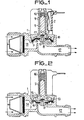
- the known type of solenoid valve is a solenoid valve with controlled opening and with an output.
- This solenoid valve comprises a body 1 surmounted by a cap 9 both made of non-magnetic material.
- a coil 2 of an electromagnet provided with a frame not shown.
- a movable core 5- made of magnetic material, this core 5 being provided, at one of its ends, with a seal 6. (rubber for example).
- a movable valve 7, intended to come to bear on a valve seat 8, is made integral with the body 1 of the solenoid valve by means of a flexible membrane 10 provided with an orifice said pilot orifice 12 of valve.
- This membrane 10 constitutes a seal when it is applied to the valve seat 8 (the solenoid valve is then in the closed position as shown in FIG. 2).
- This valve is also provided with a central channel called leakage channel 13 open at its two ends.
- the known type of solenoid valve also includes a chamber 14 called upstream chamber in communication with the water supply network, a chamber 15 pilot can be placed in communication with the chamber 14 by means of the pilot orifice 12, and a discharge pipe 17.
- this solenoid valve of known type requires a sufficiently large stroke of the movable core 5 so that, on the one hand, the leakage orifice 17 is released and, on the other hand, this movable core 5 is sufficiently distant from the 'orifice upstream of the pipe 17 so that the valve 7 does not come, when the solenoid valve opens, to be applied again to this movable core 5.
- the solenoid valve according to the invention of low electrical consumption, operating with a small displacement of the movable core, does not have these drawbacks.
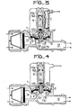
- the solenoid valve comprises, as shown in Figures 3 and 4, a solenoid valve body 1 surmounted by a cap 9 around which is placed a coil 2 of an electromagnet provided with an armature (not shown), this coil 2 ensuring the displacement of a movable core 50 of ferro-magnetic material, this movable core 50 disposed in the cap 9, being in the example shown in Figures 3 and 4 ,. provided at one of its ends with a seal 60.
- the movable core 50 is disposed a leakage channel 130 which is fixed relative to the solenoid valve and no longer integral with the movable valve as is the case in the solenoid valve of the prior art.
- This leakage channel 130 in the embodiment shown in FIGS. 3 and 4, comprises a cylindrical tube 131 surmounted by a circular plate 132 coaxial with the tube 131, provided at its center with a calibrated leak orifice 133, and provided at its periphery with passage orifices 137 allowing the circulation of the fluid.
- the solenoid valve according to the invention further comprises a movable valve 70 which is made integral with the body 1 of the solenoid valve by means of a flexible annular membrane 10, the inner edge 11 of which is flat, is inserted laterally in this valve 70, the outer edge being fixed on the body 1.
- the membrane 10 constitutes a seal between the valve 70 and a valve seat 8 when the edge 11 is applied to the valve seat 8 (the solenoid valve is then in the closed position as shown in Figure 3).
- the plane edge 11 of the membrane 10 is provided with an orifice 12 called the pilot valve orifice.
- the solenoid valve according to the invention also comprises an upstream chamber in communication with the water supply network, a pilot chamber 15 which can be placed in communication with the chamber 14 by means of the pilot orifice 12, and a manifold evacuation 17.
- the solenoid valve according to the invention further comprises, in the embodiment shown in Figures 3 and 4, a fixed core 136 secured to the electromagnet and which makes it possible to reduce the air gap of this electromagnet and of the movable core 50 and therefore of reducing the energy required to control the solenoid valve.
- the mobile core 50 being at a short distance from the fixed core 136, the energy required to call up the mobile core 50 and the energy required to maintain this mobile core 50 are very reduced compared to energies usually used for the operation of piloted solenoid valves of known type.
- a spring 160 may be disposed between the movable core 50 and the fixed core 136, this spring 160 being intended to push the movable core 50 against the leakage orifice 133 when the tension applied to the coil 2 of the electromagnet is removed.
- a sleeve 135, in the form of a bellows, is placed around the leak pipe 131, one of the ends of the sleeve 135 being fixed on the valve 70 and the other end being fixed at the junction of the circular plate 132 and- of the leakage pipe 131.
- This sleeve 135 is of such a shape and made of a material (rubber or plastic for example) such that it remains tight whatever the pressure applied to it and withstands in particular the crushing forces due to the pressure difference between the pilot chamber 15 and the evacuation pipe 17. It allows the valve 70 to open at very low pressures and forms a spring, which ensures that valve 70 is properly closed on seat 8 of this valve.
- the movable core 50 When the coil 2 is energized, the movable core 50 is attracted by the fixed core 136 associated with the electromagnet and then releases the orifice 133 from the leakage nozzle 130. The fluid of the pilot chamber 15 can then flow into the discharge pipe 17.
- the leakage orifice 133 is calibrated so that its pressure drop is less than that of the pilot orifice 12, which puts the pilot chamber 15 in depression relative to the upstream chamber 14.
- the result of the forces applied to the valve 70 is then such that this valve 70 moves away from the valve seat 8.
- the solenoid valve is open and the rest as long as the coil 2 is supplied with voltage. This tension can be lower than the tensions usually used, because the effort necessary to maintain the movable core 50 substantially against the fixed core 136 is very low. The energy consumed is then very reduced.
- the energy required for eliminating the solenoid valve according to the invention can be further reduced by choosing a spring 160 of great elasticity. It is even possible to remove this spring 160 by appropriately choosing the orientation of the solenoid valve, the leakage orifice 133 being closed by the seal 60 of the core 50 being ensured by the weight of this core 50. In this case, it may be advantageous to have between the movable core 50 and the fixed core 136 a washer made of non-magnetic material.
Priority Applications (1)
| Application Number | Priority Date | Filing Date | Title |
|---|---|---|---|
| AT81401646T ATE10779T1 (de) | 1980-11-04 | 1981-10-20 | Elektromagnetisches ventil. |
Applications Claiming Priority (2)
| Application Number | Priority Date | Filing Date | Title |
|---|---|---|---|
| FR8023521A FR2493465B1 (fr) | 1980-11-04 | 1980-11-04 | Electrovanne et machine a laver munie d'une telle electrovanne |
| FR8023521 | 1980-11-04 |
Publications (2)
| Publication Number | Publication Date |
|---|---|
| EP0051517A1 true EP0051517A1 (de) | 1982-05-12 |
| EP0051517B1 EP0051517B1 (de) | 1984-12-12 |
Family
ID=9247658
Family Applications (1)
| Application Number | Title | Priority Date | Filing Date |
|---|---|---|---|
| EP81401646A Expired EP0051517B1 (de) | 1980-11-04 | 1981-10-20 | Elektromagnetisches Ventil |
Country Status (4)
| Country | Link |
|---|---|
| EP (1) | EP0051517B1 (de) |
| AT (1) | ATE10779T1 (de) |
| DE (1) | DE3167742D1 (de) |
| FR (1) | FR2493465B1 (de) |
Cited By (8)
| Publication number | Priority date | Publication date | Assignee | Title |
|---|---|---|---|---|
| GB2123531A (en) * | 1982-07-13 | 1984-02-01 | Industry The Secretary Of Stat | Valves |
| FR2543652A1 (fr) * | 1983-03-29 | 1984-10-05 | Elbi Int Spa | Electrovalve, notamment pour machines a laver |
| DE3627543A1 (de) * | 1985-08-15 | 1987-03-12 | Smc Corp | Solenoidventil |
| US5125621A (en) * | 1991-04-01 | 1992-06-30 | Recurrent Solutions Limited Partnership | Flush system |
| EP0685672A1 (de) * | 1994-05-31 | 1995-12-06 | Daewoo Electronics Co., Ltd | Fluidventil |
| WO2005080838A2 (en) | 2004-02-23 | 2005-09-01 | Y. Stern Engineering (1989) Ltd. | Diaphragm for pilot valve |
| CN110005860A (zh) * | 2019-05-17 | 2019-07-12 | 余姚市永创电磁阀有限公司 | 一种pfa材料膜片组件及电磁阀 |
| WO2023024195A1 (zh) * | 2021-08-21 | 2023-03-02 | 浙江鸿友压缩机制造有限公司 | 一种先导型电子式卸荷阀及配装有该卸荷阀的压缩机系统 |
Families Citing this family (2)
| Publication number | Priority date | Publication date | Assignee | Title |
|---|---|---|---|---|
| KR20100138873A (ko) * | 2008-01-02 | 2010-12-31 | 마이크로플로우 인터내셔널 피티와이 리미티드 | 타임 플로우 밸브 |
| US11525524B2 (en) | 2018-02-12 | 2022-12-13 | Ceme S.P.A. | Magnetically-operable shutter assembly |
Citations (3)
| Publication number | Priority date | Publication date | Assignee | Title |
|---|---|---|---|---|
| FR1110895A (fr) * | 1954-07-19 | 1956-02-17 | Vannes électromagnétiques | |
| FR72694E (fr) * | 1957-12-30 | 1960-04-22 | Vanne | |
| US3368582A (en) * | 1965-04-22 | 1968-02-13 | American Radiator & Standard | Pilot-operated valve including removable filter |
-
1980
- 1980-11-04 FR FR8023521A patent/FR2493465B1/fr not_active Expired
-
1981
- 1981-10-20 AT AT81401646T patent/ATE10779T1/de active
- 1981-10-20 DE DE8181401646T patent/DE3167742D1/de not_active Expired
- 1981-10-20 EP EP81401646A patent/EP0051517B1/de not_active Expired
Patent Citations (3)
| Publication number | Priority date | Publication date | Assignee | Title |
|---|---|---|---|---|
| FR1110895A (fr) * | 1954-07-19 | 1956-02-17 | Vannes électromagnétiques | |
| FR72694E (fr) * | 1957-12-30 | 1960-04-22 | Vanne | |
| US3368582A (en) * | 1965-04-22 | 1968-02-13 | American Radiator & Standard | Pilot-operated valve including removable filter |
Cited By (10)
| Publication number | Priority date | Publication date | Assignee | Title |
|---|---|---|---|---|
| GB2123531A (en) * | 1982-07-13 | 1984-02-01 | Industry The Secretary Of Stat | Valves |
| FR2543652A1 (fr) * | 1983-03-29 | 1984-10-05 | Elbi Int Spa | Electrovalve, notamment pour machines a laver |
| DE3627543A1 (de) * | 1985-08-15 | 1987-03-12 | Smc Corp | Solenoidventil |
| US4717116A (en) * | 1985-08-15 | 1988-01-05 | Smc Corporation | Pilot mode two-port solenoid valve |
| US5125621A (en) * | 1991-04-01 | 1992-06-30 | Recurrent Solutions Limited Partnership | Flush system |
| EP0685672A1 (de) * | 1994-05-31 | 1995-12-06 | Daewoo Electronics Co., Ltd | Fluidventil |
| US5573224A (en) * | 1994-05-31 | 1996-11-12 | Daewoo Electronics Co., Ltd. | Water-supply valve of a washing machine |
| WO2005080838A2 (en) | 2004-02-23 | 2005-09-01 | Y. Stern Engineering (1989) Ltd. | Diaphragm for pilot valve |
| CN110005860A (zh) * | 2019-05-17 | 2019-07-12 | 余姚市永创电磁阀有限公司 | 一种pfa材料膜片组件及电磁阀 |
| WO2023024195A1 (zh) * | 2021-08-21 | 2023-03-02 | 浙江鸿友压缩机制造有限公司 | 一种先导型电子式卸荷阀及配装有该卸荷阀的压缩机系统 |
Also Published As
| Publication number | Publication date |
|---|---|
| ATE10779T1 (de) | 1984-12-15 |
| FR2493465B1 (fr) | 1985-09-13 |
| DE3167742D1 (en) | 1985-01-24 |
| FR2493465A1 (fr) | 1982-05-07 |
| EP0051517B1 (de) | 1984-12-12 |
Similar Documents
| Publication | Publication Date | Title |
|---|---|---|
| BE1006300A4 (fr) | Vanne comportant un obturateur basculant et une membrane d'isolation. | |
| EP0051517B1 (de) | Elektromagnetisches Ventil | |
| EP2045496B1 (de) | Klappenschütze mit ausgeglichenem Druck | |
| US4082116A (en) | Electromagnetic two-way valve | |
| EP0619003B1 (de) | Einhebelmischventilkartusche mit platten aus hartem material | |
| BE1000713A4 (fr) | Robinet d'arret et de commande d'ecoulement. | |
| FR2597186A1 (fr) | Soupape ou vanne fonctionnant sans frottement | |
| FR2479401A1 (fr) | Robinet de rincage et piston pour ce robinet | |
| IL156797A (en) | Diaphragm and hydraulically-operated valve using same | |
| FR2529288A1 (fr) | Dispositif d'electroaimant et son application a la commande de soupapes | |
| EP0390248B1 (de) | Vorrichtung gegen das Rücksaugen für hydraulische Einsatzhähne mit flachen Scheiben zur Stromsteuerung | |
| EP1217275B1 (de) | Bistabiles, eletromagnetisches Mikroventil | |
| EP0268521B1 (de) | Schleusenventil | |
| FR2727734A1 (fr) | Vannes de reglage a double debit | |
| EP0682615B1 (de) | Proportionales elektromagnetisch gesteuertes druckluftventil | |
| WO2011117477A1 (fr) | Robinet à fermeture temporisée | |
| FR2617562A1 (fr) | Ensemble de vanne a clapet | |
| LU100577B1 (en) | Pilot controlled electromagnetic valve with auxiliary piston | |
| FR2873778A1 (fr) | Element de clapet pour reducteur de pression equilibre | |
| EP0029387A1 (de) | Rückflussverhinderer für Trinkwasserleitung | |
| FR2543652A1 (fr) | Electrovalve, notamment pour machines a laver | |
| KR200224531Y1 (ko) | 체크밸브 | |
| CN220016091U (zh) | 截止阀 | |
| KR20020045949A (ko) | 체크밸브 | |
| SU811041A1 (ru) | Электромагнитный клапан с кольцевымСЕдлОМ |
Legal Events
| Date | Code | Title | Description |
|---|---|---|---|
| PUAI | Public reference made under article 153(3) epc to a published international application that has entered the european phase |
Free format text: ORIGINAL CODE: 0009012 |
|
| AK | Designated contracting states |
Designated state(s): AT BE CH DE FR GB IT LI LU NL SE |
|
| 17P | Request for examination filed |
Effective date: 19820818 |
|
| RAP1 | Party data changed (applicant data changed or rights of an application transferred) |
Owner name: SOCIETE ELECTRO MECANIQUE DU NIVERNAIS SELNI |
|
| ITF | It: translation for a ep patent filed |
Owner name: JACOBACCI & PERANI S.P.A. |
|
| GRAA | (expected) grant |
Free format text: ORIGINAL CODE: 0009210 |
|
| AK | Designated contracting states |
Designated state(s): AT BE CH DE FR GB IT LI LU NL SE |
|
| REF | Corresponds to: |
Ref document number: 10779 Country of ref document: AT Date of ref document: 19841215 Kind code of ref document: T |
|
| REF | Corresponds to: |
Ref document number: 3167742 Country of ref document: DE Date of ref document: 19850124 |
|
| PLBE | No opposition filed within time limit |
Free format text: ORIGINAL CODE: 0009261 |
|
| STAA | Information on the status of an ep patent application or granted ep patent |
Free format text: STATUS: NO OPPOSITION FILED WITHIN TIME LIMIT |
|
| PG25 | Lapsed in a contracting state [announced via postgrant information from national office to epo] |
Ref country code: LU Free format text: LAPSE BECAUSE OF NON-PAYMENT OF DUE FEES Effective date: 19851031 |
|
| PGFP | Annual fee paid to national office [announced via postgrant information from national office to epo] |
Ref country code: NL Payment date: 19851031 Year of fee payment: 5 Ref country code: AT Payment date: 19851031 Year of fee payment: 5 |
|
| 26N | No opposition filed | ||
| PG25 | Lapsed in a contracting state [announced via postgrant information from national office to epo] |
Ref country code: AT Effective date: 19861020 |
|
| PG25 | Lapsed in a contracting state [announced via postgrant information from national office to epo] |
Ref country code: SE Effective date: 19861021 |
|
| PG25 | Lapsed in a contracting state [announced via postgrant information from national office to epo] |
Ref country code: LI Effective date: 19861031 Ref country code: CH Effective date: 19861031 Ref country code: BE Effective date: 19861031 |
|
| BERE | Be: lapsed |
Owner name: SOC. ELECTRO MECANIQUE DU NIVERNAIS SELNI Effective date: 19861031 |
|
| PG25 | Lapsed in a contracting state [announced via postgrant information from national office to epo] |
Ref country code: NL Effective date: 19870501 |
|
| NLV4 | Nl: lapsed or anulled due to non-payment of the annual fee | ||
| PG25 | Lapsed in a contracting state [announced via postgrant information from national office to epo] |
Ref country code: FR Free format text: LAPSE BECAUSE OF NON-PAYMENT OF DUE FEES Effective date: 19870630 |
|
| REG | Reference to a national code |
Ref country code: CH Ref legal event code: PL |
|
| GBPC | Gb: european patent ceased through non-payment of renewal fee | ||
| PG25 | Lapsed in a contracting state [announced via postgrant information from national office to epo] |
Ref country code: DE Effective date: 19870701 |
|
| REG | Reference to a national code |
Ref country code: FR Ref legal event code: ST |
|
| PG25 | Lapsed in a contracting state [announced via postgrant information from national office to epo] |
Ref country code: GB Effective date: 19881118 |
|
| EUG | Se: european patent has lapsed |
Ref document number: 81401646.5 Effective date: 19870812 |