EP0051448A2 - Appareil et méthode d'impression utilisant des gouttelettes liquides - Google Patents
Appareil et méthode d'impression utilisant des gouttelettes liquides Download PDFInfo
- Publication number
- EP0051448A2 EP0051448A2 EP81305110A EP81305110A EP0051448A2 EP 0051448 A2 EP0051448 A2 EP 0051448A2 EP 81305110 A EP81305110 A EP 81305110A EP 81305110 A EP81305110 A EP 81305110A EP 0051448 A2 EP0051448 A2 EP 0051448A2
- Authority
- EP
- European Patent Office
- Prior art keywords
- drops
- drop
- target
- scan line
- streams
- Prior art date
- Legal status (The legal status is an assumption and is not a legal conclusion. Google has not performed a legal analysis and makes no representation as to the accuracy of the status listed.)
- Granted
Links
- 239000007788 liquid Substances 0.000 title claims abstract description 35
- 238000007639 printing Methods 0.000 title claims abstract description 17
- 238000000034 method Methods 0.000 title claims description 13
- 230000033001 locomotion Effects 0.000 claims abstract description 17
- 230000005686 electrostatic field Effects 0.000 claims abstract description 5
- 230000008878 coupling Effects 0.000 claims description 4
- 238000010168 coupling process Methods 0.000 claims description 4
- 238000005859 coupling reaction Methods 0.000 claims description 4
- 230000008859 change Effects 0.000 claims description 3
- 230000008569 process Effects 0.000 description 5
- 230000015572 biosynthetic process Effects 0.000 description 3
- 235000009508 confectionery Nutrition 0.000 description 3
- 230000000638 stimulation Effects 0.000 description 3
- 230000008901 benefit Effects 0.000 description 2
- 238000012937 correction Methods 0.000 description 2
- 230000005484 gravity Effects 0.000 description 2
- 230000006698 induction Effects 0.000 description 2
- 239000002184 metal Substances 0.000 description 2
- 229910052751 metal Inorganic materials 0.000 description 2
- 230000004048 modification Effects 0.000 description 2
- 238000012986 modification Methods 0.000 description 2
- 238000000926 separation method Methods 0.000 description 2
- 238000010408 sweeping Methods 0.000 description 2
- RYGMFSIKBFXOCR-UHFFFAOYSA-N Copper Chemical compound [Cu] RYGMFSIKBFXOCR-UHFFFAOYSA-N 0.000 description 1
- 238000013459 approach Methods 0.000 description 1
- 230000005540 biological transmission Effects 0.000 description 1
- 239000004020 conductor Substances 0.000 description 1
- 229910052802 copper Inorganic materials 0.000 description 1
- 239000010949 copper Substances 0.000 description 1
- 238000006073 displacement reaction Methods 0.000 description 1
- 230000000694 effects Effects 0.000 description 1
- 239000012777 electrically insulating material Substances 0.000 description 1
- 239000012530 fluid Substances 0.000 description 1
- 238000003384 imaging method Methods 0.000 description 1
- 238000012423 maintenance Methods 0.000 description 1
- 238000004519 manufacturing process Methods 0.000 description 1
- 239000000463 material Substances 0.000 description 1
- 239000011159 matrix material Substances 0.000 description 1
- 230000003287 optical effect Effects 0.000 description 1
- 238000004806 packaging method and process Methods 0.000 description 1
- 238000012856 packing Methods 0.000 description 1
- 230000002093 peripheral effect Effects 0.000 description 1
- 229920000642 polymer Polymers 0.000 description 1
- 238000005086 pumping Methods 0.000 description 1
- 238000007493 shaping process Methods 0.000 description 1
- 229910052709 silver Inorganic materials 0.000 description 1
- 239000004332 silver Substances 0.000 description 1
- -1 silver halide Chemical class 0.000 description 1
- 239000007787 solid Substances 0.000 description 1
- 230000003068 static effect Effects 0.000 description 1
Images
Classifications
-
- B—PERFORMING OPERATIONS; TRANSPORTING
- B41—PRINTING; LINING MACHINES; TYPEWRITERS; STAMPS
- B41J—TYPEWRITERS; SELECTIVE PRINTING MECHANISMS, i.e. MECHANISMS PRINTING OTHERWISE THAN FROM A FORME; CORRECTION OF TYPOGRAPHICAL ERRORS
- B41J2/00—Typewriters or selective printing mechanisms characterised by the printing or marking process for which they are designed
- B41J2/005—Typewriters or selective printing mechanisms characterised by the printing or marking process for which they are designed characterised by bringing liquid or particles selectively into contact with a printing material
- B41J2/01—Ink jet
- B41J2/07—Ink jet characterised by jet control
- B41J2/075—Ink jet characterised by jet control for many-valued deflection
- B41J2/08—Ink jet characterised by jet control for many-valued deflection charge-control type
- B41J2/09—Deflection means
Definitions
- This invention relates to a liquid drop apparatus and method for printing with drops on a target in alignment with the pixels of a linear scan line of a raster image.
- U.S. Patent 3,596,275 to Sweet describes a printing, marking, recording or imaging system of the present type.
- a continuous stream of drops is formed from a column of liquid emitted from a nozzle under pressure.
- the drops are charged as they pass through a tunnel electrode.
- an electrostatic field created between a pair of planar electrodes or plates on opposite sides of the drop stream deflect charged drops proportionally to their charge.
- the drops are spread out in a straight line on a stationary target at which they are directed.
- the nozzle and target usually move generally normal to the electrostatic deflection field. Consequently, the line pattern created by the deflection process is distorted by the relative movement.
- U.S. Patents 3,813,676 and 4,054,882 both disclose tilting the deflection plates relative to a print line to correct for distortion.
- the distortion being corrected is that due to relative movement between a target and a drop generator.
- These patents refer to single nozzle systems that print characters in a prescribed M x N matrix pattern of pixels.
- U.S. 4,054,882 also talks about the compensation being accomplished "by a change in the bit train from the character generator or other source.”
- An International Business Machine Company (IBM) Technical Disclosure Bulletin (TDB) of Gamblin and Marcus, Vol. II, No. 10, pp. 1292-3 dated March 1969 also discloses a tilted deflection zone.
- U.S. Patent 4,194,210 discloses a Sweet type printing system having plural nozzles and a zig-zag deflection electrode structure, providing a binary deflection system.
- a binary deflection system is one in which the drops are routed between either of two flight paths: one that strikes the target and all others that intersect a gutter.
- a multiple deflection system is one in which the drops are routed between three or more flight paths with at least two paths leading to a pixel position on a target.
- the system is a multiple nozzle device but includes two pairs of deflection plates arranged orthogonally to each other. One pair of plates are parallel and are oriented without any tilt. These plates affect deflection along an x axis. The other pair of plates affect deflection along a y axis. The plates of this other pass are not parallel to each other but rather have the first plate at a slight angle to the horizontal second plate.
- the present invention is intended to provide a simplified liquid drop printing apparatus and method without the attendant disadvantages of the known systems.
- the apparatus of the invention is characterised by drop generating means for generating a plurality of drop streams in flight toward a target including a linear array of nozzles for emitting liquid under pressure to create liquid columns from which the drops are formed, the nozzle spacing within the array being a distance enabling drops from a single nozzle to address multiple pixels within a segment of a raster image scan line at the target,
- This apparatus compensates for distortions in a scan or print line of drops due to relative motion of the drop generator and target in a printing system having multiple nozzles collectively defining a straight scan line by having each nozzle construct a segment of the scan line.
- the apparatus of the invention includes upper and lower deflection electrodes each having a plurality of teeth interleaved with each other.
- Each electrode resembles a garden rake.
- the teeth of the upper electrode are pointed downward and the teeth of the lower electrode are pointed upward.
- the sides of the teeth are electrically conductive and the spaces between the side surfaces of the teeth define the drop deflection zones.
- the upper electrodes are coupled to a potential of about 2000 volts, for example, and the lower teeth are coupled to ground potential.
- a tilt is given to the deflection zone by shaping the cross-section of the teeth as a full or truncated triangle.
- the triangular cross-section of the teeth alternates the tilt for every other deflection zone between positive and negative slopes.
- the alternating slopes to adjacent deflection zones as well as the interleaving technique are especially important for the guttering operation.
- adjacent drop streams share a common gutter.
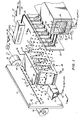
- the printing system 1 of Figure 1 is a Sweet type (U.S. Patent 3,596,275 supra) liquid drop system. It employs many parallel drop streams 2 located generally in the same plane to construct a straight line 3 of drops across a target 4. Drops from each drop stream are electrostatically deflected laterally in the plane of the streams (generally) to construct segments 5 of line 3. A segment contains two or more drops. A segment containing a single drop is a binary deflection system of the type alluded to earlier, whereas, the present system is a multiple deflection system.
- a line of drops 3 is called a print line and it overlays an imaginary line called a raster scan line composed of pixels.
- a pixel is representative of the reflection or transmission, optical density of an elemental area of a two dimensional image. It is ideally the same size as a liquid drop impacted on the target.
- a collection of parallel scan lines defines a raster scan image.
- a raster image may be textual or pictorial.
- a textual image is one composed of discrete characters such as appearing on this page.
- a pictorial image is one composed of lines and curves such as graphs and charts.
- a pictorial image also includes an image containing continuous tone information such as a silver halide photographic print or slide as reproduced by a lithographic printing process or a television display device.
- Both textual and pictorial images are reproduced by system 1 in a raster scan pattern.
- Multiple parallel print lines 3 are created on the target 4 by moving the target and drop streams relative to each other.
- a single drop is placed at a drop position within a print line if the corresponding pixel location within a scan line of an electrical raster image calls for a drop at that location.
- a significant aspect of this invention is that multiple drops from each drop stream form a segment of a full print line.
- prior art multiple nozzle systems use the drops from each stream to create independent images.
- Patent 3,828,354 to Howard Hilton is an example of a system in which each drop stream (see streams 16 in Figure 1 of the patent) in an array of streams creates one or more alpha numeric characters independently of the other drop streams.
- the multiple streams in the Hilton patent are merely a row of independent character generators.
- the multiple streams in this invention act collectively to create an image the full width of a target.
- the image may be a line of characters but at least some characters in the line are constructed by two or more drop streams.
- the multiple drop streams 2 are created by the drop generator 10.
- the generator includes a body 11 or manifold having a cavity 12 for containing a liquid ink 13 under pressure.
- the liquid is supplied to the cavity via an inlet conduit 14 coupled to a source of liquid under pressure as represented by arrow 15.
- the source is conventionally a fluid pump (not shown) pumping the liquid from a reservoir (not shown) to the manifold cavity 12.
- the operating liquid pressure in the cavity is from about 0.7 to 7.0 kg.cm .
- the body 11 has an aperture plate 17 coupled to it that contains a straight row or array of nozzles 18.
- a nozzle is a cylindrical hole cut into the aperture plate.
- Other cross sectional shapes are possible for the orifice.
- Continuous streams or columns 19 of liquid are emitted from the nozzles 18 due to the liquid pressure in the cavity 12.
- the drop streams 2 are generated from the columns 19 at fixed distances from the nozzles due to acoustic stimulation of the liquid in the cavity by the transducer 20.
- Transducer 20 is located against the wall of cavity 12 opposite the wall containing the nozzles.
- the layer 20 is representative of a transducer inlcuding a piezoelectric material and associated electrodes that electrically operate it.
- the transducer varies the amplitude of the pressure in the chamber by a comparatively small amount at a frequency near the desired drop generation frequency.
- the stimulation of the liquid by transducer 20 promotes the formation of drops 2 at the rate of stimulation.
- the drop generation rate is at least from about 100,000 drops per second (dps) to over 200,000 dps.
- the drops from all the nozzles are generated at a fixed distance from the nozzles and are of uniform size and spacing.
- the controller 6 electrically drives the transducer 20 at the desired rate via the line 21 and amplifier 22 which couple the transducer to the controller.
- the controller 6 includes a microprocessor, customary peripheral components and appropriate interface equipment for orchestrating the operations of the entire system 1.
- An Intel Corporation Model 8080 microcomputer and its standard support and interface modules is an example of an appropriate system.
- the software for the controller is dictated by the specific operation of specific systems.
- the charging electrodes 23 are positioned at the region of drop formation.
- the liquid is electrically grounded through the manifold 11 as indicated by the ground symbol 24.
- the charging electrodes are conductive, cylindrical tunnels.
- a voltage coupled to a charging electrode over a wire in bundle 25 by the controller 6 induces a charge in the grounded liquid.
- the drop breaks off from a column 19 and the induced charge is trapped in the drop.
- the amount of trapped charge is proportional to the applied voltage.
- Typical charging voltages are from a few to over 200 volts. A presently preferred range is from about -130 to + 130 volts.
- the polarity of the applied voltage affects the direction in which a drop is deflected within a constant deflection field.
- the charging electrodes 23 are fabricated on an insulating board member 26. A linear array of cylindrical holes are cut into the board. The holes have a diameter of about 10 to 20 drop diameters. These holes are electroplated with copper or other conductive metal to create the cylindrical conductive tunnels 23. Thin layers of a conductive metal 27 are also created on the board 26 by conventional printed circuit board techniques to connect the tunnels 23 to a wire in the bundle 25 coupling the tunnel to controller 6.
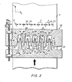
- Zones 30 are the nearly vertical spaces between the upper teeth 31 and lower teeth 32 of the upper and lower deflection electrodes 33 and 34. Electrodes 33 and 34 are conductive members coupled to a high +B potential and ground potential 24, respectively as indicated in Figure 1.
- a deflection zone is sometimes referred to as either a “left” or “right” zone.
- the intended orientation is that based on the lower teeth 32. That is, the deflection zones to the left and right of a lower tooth define the left and right orientation intended.
- the upper and lower teeth 31 and 32 have truncated, triangular cross sections.
- the right side surface 35 of each upper tooth 31 is spaced from and generally parallel to the left side surface 36 of each lower tooth 32 thereby defining a "left" deflection zone.
- the left zones have a positive slope or tilt as is explained more succinctly in connection with a discussion of Figures 2 and 3.
- right side surface 37 of each lower tooth and a left side surface 38 of each upper tooth 31 define "right" deflection zones.
- the right zones have a negative slope or tilt. Again, the sign or polarity of a slope is defined more fully in connection with Figures 2 and 3.
- the upper teeth point downwardly into the spaces 29 between the lower teeth at their midpoint.
- the lower teeth point upwardly into the spaces 2 8 between the upper teeth at their midpoints.
- the cross sections of the upper and lower teeth are parts of geometrically similar triangles. Consequently, the side surfaces 35 and 36, are parallel and the sides 37 and 38 are parallel.
- the angle 8 ( Figure 2) of the triangular cross-sections of the teeth determines the slope or tilt of the left and right deflection zones. Clearly, every other deflection zone has a slope of opposite polarity.
- the tilt or slope of a left or right deflection zone compensates for the relative motion between the target 4 and the drop stream.
- the target is driven upwardly past the stationary drop generator 10 in a direction normal to the row or array of nozzles 18.
- a target transport is provided by the wheels 39 coupled to a common shaft 40.
- the shaft 40 is rotated by the motor 41.
- the controller 6 regulates the operation of motor 41 over an appropriate line 42 and amplifier 43.
- the wheels frictionally engage the back surface of the target 4 to drive the target upwardly in Figure 1.
- the target is driven by the wheels at a speed to displace the target vertically by an amount separating scan lines in the raster image.
- Gutters 46 are located adjacent each lower tooth 32 of the lower deflection electrode 34. Each gutter serves the two adjacent drop streams. The drops not intended for the print line 3 on the target are deflected into a gutter. Each gutter is triangular shaped similar to that of the lower teeth and each is positioned close to the downstream end of a tooth. The gutter position is chosen not to interfere with the flight of drops intended for all the pixels within a segment of a scan line.
- the end pixels in each segment 5 are one pixel away from end pixels in adjacent segments addressed by adjacent nozzles. This is necessary for the nozzles 18 to collectively create a continuous scan line the width of target 4.
- the alignment of the drops to the pixel positions as described requires careful calibration of drop charging.
- the processes of aligning drops in one segment to those in adjacent segments is referred to as "stitching.”
- the reader is referred to European Patent Publication no. 0815727, which describes the stitching process and means for carrying it out.
- Gutters 46 have openings or mouths 47 that are wide enough to receive drops from the streams in flight in both left and right deflection zones on either side of a lower tooth.
- Notches 48 are cut out from the side surfaces 36 and 37 of each lower tooth to increase the clearance between the side surfaces of the lower teeth and the gutters. The notches allow drops to fly into the mouths 47.
- a notch is wedge-shaped with the apex at a surface. 36 or 37 and the base adjacent a gutter mouth 47.
- the notches 48 are located at elevations on the teeth 32 to provide a flight path for drops deflected by the fields into the mouth 47 of a gutter. (See Figures I and 2).
- the gutters are hood-like and serve as conduits for the collected liquid.
- the gutters have interior cavities that allow the liquid from collected drops to flow into the cavity 51 of gutter manifold 49.
- a vacuum i.e. a pressure below atmospheric, is coupled to the manifold 49 via an appropriate conduit 50.
- the vacuum conduit 50 returns the liquid to the system reservoir (not shown) for recirculation to the drop generator 10.
- the triangular cross-sectional shape of the teeth is suited for locating a gutter 46 near the downstream end of a tooth.
- the triangular shape gives a thickness to the deflection electrodes that can accommodate gutters having a meaningful width.
- the lower teeth are preferred over the upper teeth for the location of the gutters 46. The reason is that the lower tooth location enables the gutters to make use of gravity for the desired flow for the collected liquid. Of course, this advantage for the lower teeth is lost if the printer orientation is rotated ninety degrees. Nonetheless, it is still preferred to locate the gutters 46 adjacent the teeth that are coupled to the same potential as the liquid: ground potential in the example of Figure 1.
- the left pointing 52 and right pointing 53 arrows in Figures 1 and 2 represent the sweep directions of the drop streams in the left and right deflection zones. Both sweep directions 52 and 53 are outward'rather than inward relative to the gutters 46. By outward is meant that the sequence in which drops are charged proceeds in a manner such that a trace of drops grows outwardly from the gutter. Conversely, an inward sweep is one in which the charging sequence begins with the drop to be placed farthest from a gutter and proceeds inwardly toward the gutter.
- the sweep directions for the left and right sensing zones are both outward to correct for placement errors caused by the motion of the target in a particular direction. If the target direction of travel is reversed, the sweep direction must be reversed. This assumes that the direction of the deflection fields and the polarities of the charge on the drops remains the same.
- the sweep directions 52 and 53 are opposite to each other because the same charge polarities are applied to drops in all the drop streams and because the directions of the deflection fields are opposite in every other deflection zone.
- the opposite field directions are aresult of a grounded lower tooth 32 having two + B biased, upper teeth 31 on either side of it.
- the print line 3 in Figure 2 is one formed at an earlier time when a line on moving target 4 was at the region opposite the array of drop streams 2.
- the drawing of Figure 2 is unduly cluttered when a print line 3 is drawn along the position occupied by the drop stream 2. Accordingly, that line was omitted in preference for the line shown.
- the tilt of the left deflection zone (teeth sides 35 and 36) and of the right deflection zone (teeth sides 37 and 38) are opposite to each other.
- the different tilts correct or compensate for the relative motion error associated with adjacent streams being swept in opposite directions as indicated by arrows 52 and 53.
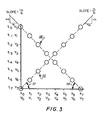
- the graph in Figure 3 includes plots of liquid drops on a moving target 4 for both a leftward 52 and rightward 53 scan or sweep.
- the deflection field deflecting the drops is not tilted. That is, surfaces 35-38 are vertical for the purposes of Figure 3.
- the plot or row of drops 55 is the trace made by sweeping eight consecutive drops in a single stream 2 from right to left--for a given target direction of travel--as represented by arrow 52 in Figures 1 and 2.
- the plot or row of drops 56 is the trace made by sweeping eight consecutive drops in a stream 2 from left to right--for a given target direction of travel--as represented by arrow 53 in Figures 1 and 2.
- the relative velocity of the target 4 to the nozzles 18 is the same. If the direction of relative travel is reversed, the slopes of traces 55 and 56 are reversed. Similarly, the slopes of plots 55 and 56 can be reversed by charging the drops in the opposite sequence even though the direction of target travel is unchanged.
- the 45 degree angles 57 and 58 for plots 55 and 56 are chosen for convenience. Angles 57 and 58 correspond to angle 8 in Figure 2.
- the actual tilt from horizontal in high speed printing systems ranges from about 2 degrees to about 12 degrees for plots 55 and 56.
- the slope of plot 55 is positive as defined by the ratio of a/b as shown in Figure 3.
- the slope of plot 56 is negative as defined by the ratio of -a/b as shown in Figure 3.
- the slope 8 of the side surfaces 35 and 36 of the teeth defining a left deflection zone is selected to compensate for motion error associated with a leftward sweep 52 of a drop stream.
- the object is to have eight consecutive drops, in this example, traced as a horizontal line or sweep on the target. Consequently, the surfaces 35 and 36 ( Figure 2) are tilted clockwise from vertical by an angle 6 equal to angle 57. Likewise, the surfaces 37 and 38 defining the right deflection zones ( Figure 2) are tilted counterclockwise from vertical by an angle 8 equal to angle 58. This angle 6 compensates for motion error associated for a rightward sweep 53 of a drop stream.
- a segment 5 of a scan or print line 3 is created by a single drop stream using a linear charging scheme as illustrated by Figure 3.
- a line segment 5 is made up of eight pixel or drop positions represented by X o through X 7 .
- Charging voltages applied to a charging electrode 23 enable the eight pixels within a segment to be addressed by a drop from a stream 2. That is, voltage V 0 applied to the charging electrode at a moment just prior to and during drop separation from a continuous stream 19 charges or "addresses" that drop to a level such that the field in a deflection zone positions it to pixel location X 0 .
- voltages V through V 7 applied to a charging electrode at the moment of drop separation addresses drops rspectively to corresponding pixel positions X l through X 7 .
- the drops are not offset from the horizontal segment 5 as indicated by plots 55 and 56 in Figure 3 because the deflection zone is appropriately tilted and the sweep direction, i.e. either inward or outward of a gutter, is appropriately selected to compensate for the relative motion error.
- the presently preferred charging scheme for system 1 is a bipolar scheme. This means that the voltages V through V 7 in Figure 3 range from some negative value to some positive value, for example from -130 volts to +130 volts. A zero volt level causes a drop to strike the target following a non-deflected flight path but that particular charge level may not be used because it does not place a drop at one of the pixels within a line segment.
- the positive and negative polarities enable drops to be deflected left and right from a non-deflected flight path.
- the upper and lower teeth are coupled to +B and ground potentials respectively.
- Drops in left deflection zones are deflected outwardly from a gutter 46 by linearly increasing the voltage applied to a charging electrode 23 from -130 volts (the X o position in Figure 3) to + 130 volts (the X 7 position in Figure 3).
- Drops in right deflection zones are also deflected outwardly by linearly increasing the voltage applied to a charging electrode 23 from -130 volts to + 130 volts.
- a charging voltage less than -130 volts is used to gutter a drop in both the left and right deflection zones.
- the additional error sources include: induction error; electrostatic error; and aerodynamic error. These errors are corrected or minimized by techniques that do not change the tilt scheme disclosed herein. However, the magnitude of the tilt of a deflection zone relative to a print line is affected by the drop interlacing scheme used to compensate for errors. The tilt angle is increased when interlacing is used. Interlacing involves constructing a line segment 5 during two or more sweeps of a drop stream.
- the eight pixels of segment 5 in Figure 3 are addressed as follows: X0, X 3 and X 6 are addressed during the first sweep involving eight clock periods; X l l X 4 and X 7 are addressed during the second sweep; and X 2 and X s are addressed during the third sweep.
- the deflection field is tilted an angle three times the angle needed if all eight pixels were addressed during one sweep at the same clock or sweep rate.
- the dimensions involved with system 1 of Figure 1 for a good quality printing system are important.
- the target 4 is conventionally 21.6 x 27.9cm plainpaper or a near size such as an A4 European paper size.
- a scan line 3 contains 2550 pixels. This sets the maximum pixel dimension to about 85 microns.
- the pixel dimension is selected to equal that of a drop after impact on a target. A drop expands by about twice its inflight size upon impact with the target.
- the presently preferred approach for a multiple deflection system is to employ scan line segments 5 having about 26 pixel positions. This means that about one hundred nozzles 18 are able to supply the roughly 2600 drops to a target to make a solid print line.
- the above example sets the nozzle to nozzle spacing 60 (Figure 1) to about 2.16mm.
- the drop stream to drop stream spacing 61 (see Figure 2) is the same as that of the nozzle spacing.
- the widths 62 and 63 ( Figure 2) of both the upper and lower teeth 31 and 32 are the same at least at the elevation in which drop deflection occurs.
- the width 64 of the deflection zones 30 at least at the deflection elevations are all the same.
- the sum of a zone width 64 and of a tooth width is equal to the drop stream to drop stream spacing 61.
- the deflection zone width 64 is less than a segment 5 because the drops fan outwardly to the ends of a segment due to the electrostatic deflection exerted on the drops during their flight through the deflection zone.
- the deflection zone need be only about ten drop diameters wide.
- the interleaving of the upper and lower teeth 31 and 32 is well suited for fabrication of deflection electrodes of the above dimensions.
- the deflection electrodes 33 and 34 are readily separated during start up and shut down of the drop streams. During those times it is possible for liquid to electrically short the deflection plates represented by side surfaces 35-38. Moving the upper and lower electrodes away from each other, up and down in the example here, removes the surfaces 35-38 from the vicinity of streams 2.
- a double threaded shaft 65 journaled to the upper and lower electrodes 33 and 34 by bushings 66 and 67 is an appropriate device for moving the interleaved teeth from the operative position shown to a non-operative position.
- a handle 68 is turned clockwise to separate the upper and lower teeth. The threads in the region 69 are wound oppositely to those in region 70.
- a similar threaded shaft (not shown) coupled in like fashion to the charging electrode board 26 offers similar advantages.
- the board 26 is severed along a line running through the centers of the charging tunnels 23.
- the two halves of board 26 above and below line are separated during start up and shut down of the drop streams 2.
- the liquid from which the drops are formed can be coupled to some potential other than ground.
- the teeth 31 and 32 need not be sloped from vertical and the motion error can be corrected by shifting the timing of the selection of drops for charging drops to levels corresponding to a pixel address within a segment of a scan or print line.
- the dimensions given in the embodiments can be scaled up or down.
- the number of nozzles 18 can be selected to be less than the width of the target and the nozzles can be moved relative to the target along the x axis as well as the y axis.
- the upper and lower members 33 and 34 are made from an electrically insulating material such as a polymer having good mechanical strength.
- a conductive material is placed on the teeth surfaces 35-38 so that the electrostatic deflection fields can be created.
- Appropriate means for coupling these surfaces 35-38 to the + B and ground potentials (or other selected potentials) is required.
Landscapes
- Particle Formation And Scattering Control In Inkjet Printers (AREA)
Applications Claiming Priority (2)
| Application Number | Priority Date | Filing Date | Title |
|---|---|---|---|
| US06/203,210 US4347521A (en) | 1980-11-03 | 1980-11-03 | Tilted deflection electrode method and apparatus for liquid drop printing systems |
| US203210 | 1980-11-03 |
Publications (3)
| Publication Number | Publication Date |
|---|---|
| EP0051448A2 true EP0051448A2 (fr) | 1982-05-12 |
| EP0051448A3 EP0051448A3 (en) | 1983-08-17 |
| EP0051448B1 EP0051448B1 (fr) | 1986-07-23 |
Family
ID=22752974
Family Applications (1)
| Application Number | Title | Priority Date | Filing Date |
|---|---|---|---|
| EP81305110A Expired EP0051448B1 (fr) | 1980-11-03 | 1981-10-28 | Appareil et méthode d'impression utilisant des gouttelettes liquides |
Country Status (5)
| Country | Link |
|---|---|
| US (1) | US4347521A (fr) |
| EP (1) | EP0051448B1 (fr) |
| JP (1) | JPS57107855A (fr) |
| CA (1) | CA1168295A (fr) |
| DE (1) | DE3174988D1 (fr) |
Cited By (2)
| Publication number | Priority date | Publication date | Assignee | Title |
|---|---|---|---|---|
| WO2013142451A1 (fr) * | 2012-03-20 | 2013-09-26 | Eastman Kodak Company | Réduction d'erreur de disposition de gouttes dans une imprimante électrostatique |
| US8646882B2 (en) | 2012-03-20 | 2014-02-11 | Eastman Kodak Company | Drop placement error reduction in electrostatic printer |
Families Citing this family (11)
| Publication number | Priority date | Publication date | Assignee | Title |
|---|---|---|---|---|
| US4682183A (en) * | 1986-07-21 | 1987-07-21 | Xerox Corporation | Gutter for an ink jet printer |
| US6276589B1 (en) | 1995-09-25 | 2001-08-21 | Speedline Technologies, Inc. | Jet soldering system and method |
| US5894980A (en) * | 1995-09-25 | 1999-04-20 | Rapid Analysis Development Comapny | Jet soldering system and method |
| US5868305A (en) * | 1995-09-25 | 1999-02-09 | Mpm Corporation | Jet soldering system and method |
| US5938102A (en) * | 1995-09-25 | 1999-08-17 | Muntz; Eric Phillip | High speed jet soldering system |
| US5894985A (en) * | 1995-09-25 | 1999-04-20 | Rapid Analysis Development Company | Jet soldering system and method |
| US6186192B1 (en) | 1995-09-25 | 2001-02-13 | Rapid Analysis And Development Company | Jet soldering system and method |
| AU2003296256A1 (en) * | 2003-09-22 | 2005-04-11 | Ten Cate Advanced Textiles B.V. | Method and device for digitally upgrading textile |
| US7364277B2 (en) * | 2004-04-14 | 2008-04-29 | Eastman Kodak Company | Apparatus and method of controlling droplet trajectory |
| US7273269B2 (en) | 2004-07-30 | 2007-09-25 | Eastman Kodak Company | Suppression of artifacts in inkjet printing |
| US7261396B2 (en) * | 2004-10-14 | 2007-08-28 | Eastman Kodak Company | Continuous inkjet printer having adjustable drop placement |
Citations (2)
| Publication number | Priority date | Publication date | Assignee | Title |
|---|---|---|---|---|
| US3813676A (en) * | 1972-10-05 | 1974-05-28 | Ibm | Non-sequential symbol generation system for fluid jet printer |
| US4194210A (en) * | 1976-03-29 | 1980-03-18 | International Business Machines Corporation | Multi-nozzle ink jet print head apparatus |
Family Cites Families (3)
| Publication number | Priority date | Publication date | Assignee | Title |
|---|---|---|---|---|
| US3298030A (en) * | 1965-07-12 | 1967-01-10 | Clevite Corp | Electrically operated character printer |
| US3786517A (en) * | 1972-09-05 | 1974-01-15 | Ibm | Ink jet printer with ink system filter means |
| US4054882A (en) * | 1973-01-22 | 1977-10-18 | International Business Machines Corporation | Non-sequential ink jet printing |
-
1980
- 1980-11-03 US US06/203,210 patent/US4347521A/en not_active Expired - Lifetime
-
1981
- 1981-09-30 CA CA000386973A patent/CA1168295A/fr not_active Expired
- 1981-10-27 JP JP56171967A patent/JPS57107855A/ja active Pending
- 1981-10-28 EP EP81305110A patent/EP0051448B1/fr not_active Expired
- 1981-10-28 DE DE8181305110T patent/DE3174988D1/de not_active Expired
Patent Citations (2)
| Publication number | Priority date | Publication date | Assignee | Title |
|---|---|---|---|---|
| US3813676A (en) * | 1972-10-05 | 1974-05-28 | Ibm | Non-sequential symbol generation system for fluid jet printer |
| US4194210A (en) * | 1976-03-29 | 1980-03-18 | International Business Machines Corporation | Multi-nozzle ink jet print head apparatus |
Non-Patent Citations (1)
| Title |
|---|
| IBM TECHNICAL DISCLOSURE BULLETIN, vol. 12, no. 11, April 1970, New York, J.W. HASKELL et al. "Deflecting plate assembly for multiple ink jet printer", page 2001 * |
Cited By (3)
| Publication number | Priority date | Publication date | Assignee | Title |
|---|---|---|---|---|
| WO2013142451A1 (fr) * | 2012-03-20 | 2013-09-26 | Eastman Kodak Company | Réduction d'erreur de disposition de gouttes dans une imprimante électrostatique |
| US8646883B2 (en) | 2012-03-20 | 2014-02-11 | Eastman Kodak Company | Drop placement error reduction in electrostatic printer |
| US8646882B2 (en) | 2012-03-20 | 2014-02-11 | Eastman Kodak Company | Drop placement error reduction in electrostatic printer |
Also Published As
| Publication number | Publication date |
|---|---|
| EP0051448A3 (en) | 1983-08-17 |
| CA1168295A (fr) | 1984-05-29 |
| DE3174988D1 (en) | 1986-08-28 |
| EP0051448B1 (fr) | 1986-07-23 |
| US4347521A (en) | 1982-08-31 |
| JPS57107855A (en) | 1982-07-05 |
Similar Documents
| Publication | Publication Date | Title |
|---|---|---|
| EP0051448B1 (fr) | Appareil et méthode d'impression utilisant des gouttelettes liquides | |
| US4122458A (en) | Ink jet printer having plural parallel deflection fields | |
| EP0113499B1 (fr) | Imprimante à jet d'encre | |
| US4219822A (en) | Skewed ink jet printer with overlapping print lines | |
| US4274100A (en) | Electrostatic scanning ink jet system | |
| CA1089913A (fr) | Imprimante par points bidirectionnelle | |
| CA1089916A (fr) | Dispositif pour tete d'impression par jet d'encre a orifices multiples | |
| CA1133042A (fr) | Lentille electrostatique a champs multiples pour imprimante a jets d'encre | |
| US4194210A (en) | Multi-nozzle ink jet print head apparatus | |
| EP0015727A1 (fr) | Appareil d'impression à jet d'encre électrostatique et procédé | |
| US4533925A (en) | Ink jet printer with non-uniform rectangular pattern of print positions | |
| CA1068328A (fr) | Tete d'impression a gicleurs d'encre multiples obliques | |
| US7438396B2 (en) | Inkjet printing method and apparatus | |
| US5801734A (en) | Two row flat face charging for high resolution printing | |
| US4550323A (en) | Elongated fluid jet printing apparatus | |
| US4314258A (en) | Ink jet printer including external deflection field | |
| EP0723870B1 (fr) | Impression d'images à échelles de gris par un réseau de jets d'encre à haute résolution | |
| GB2144678A (en) | Ink jet printing | |
| CA1129938A (fr) | Lentille electrostatique pour imprimante au jet d'encre | |
| JPS5838170A (ja) | インクジエツト用マルチノズルヘツド | |
| EP0049624B1 (fr) | Imprimante à jet d'encre en mode d'opération binaire | |
| US5325121A (en) | Method and apparatus for correction of focusing artifacts in ionographic devices | |
| EP0043295B1 (fr) | Enregistreur de gouttelettes de fluide | |
| CA1129932A (fr) | Methode d'impression a jet d'encre par balayage electrostatique | |
| JPS61173950A (ja) | 荷電量制御型インクジエツト記録装置 |
Legal Events
| Date | Code | Title | Description |
|---|---|---|---|
| PUAI | Public reference made under article 153(3) epc to a published international application that has entered the european phase |
Free format text: ORIGINAL CODE: 0009012 |
|
| AK | Designated contracting states |
Designated state(s): DE FR GB |
|
| 17P | Request for examination filed |
Effective date: 19821004 |
|
| PUAL | Search report despatched |
Free format text: ORIGINAL CODE: 0009013 |
|
| AK | Designated contracting states |
Designated state(s): DE FR GB |
|
| GRAA | (expected) grant |
Free format text: ORIGINAL CODE: 0009210 |
|
| AK | Designated contracting states |
Kind code of ref document: B1 Designated state(s): DE FR GB |
|
| ET | Fr: translation filed | ||
| REF | Corresponds to: |
Ref document number: 3174988 Country of ref document: DE Date of ref document: 19860828 |
|
| PLBE | No opposition filed within time limit |
Free format text: ORIGINAL CODE: 0009261 |
|
| STAA | Information on the status of an ep patent application or granted ep patent |
Free format text: STATUS: NO OPPOSITION FILED WITHIN TIME LIMIT |
|
| 26N | No opposition filed | ||
| PG25 | Lapsed in a contracting state [announced via postgrant information from national office to epo] |
Ref country code: DE Effective date: 19880701 |
|
| PGFP | Annual fee paid to national office [announced via postgrant information from national office to epo] |
Ref country code: FR Payment date: 19890911 Year of fee payment: 9 |
|
| PGFP | Annual fee paid to national office [announced via postgrant information from national office to epo] |
Ref country code: GB Payment date: 19890930 Year of fee payment: 9 |
|
| PG25 | Lapsed in a contracting state [announced via postgrant information from national office to epo] |
Ref country code: GB Effective date: 19901028 |
|
| GBPC | Gb: european patent ceased through non-payment of renewal fee | ||
| PG25 | Lapsed in a contracting state [announced via postgrant information from national office to epo] |
Ref country code: FR Effective date: 19910628 |
|
| REG | Reference to a national code |
Ref country code: FR Ref legal event code: ST |