EP0051447A1 - Agrafeuse - Google Patents
Agrafeuse Download PDFInfo
- Publication number
- EP0051447A1 EP0051447A1 EP81305109A EP81305109A EP0051447A1 EP 0051447 A1 EP0051447 A1 EP 0051447A1 EP 81305109 A EP81305109 A EP 81305109A EP 81305109 A EP81305109 A EP 81305109A EP 0051447 A1 EP0051447 A1 EP 0051447A1
- Authority
- EP
- European Patent Office
- Prior art keywords
- staple
- stapling
- legs
- sheets
- staples
- Prior art date
- Legal status (The legal status is an assumption and is not a legal conclusion. Google has not performed a legal analysis and makes no representation as to the accuracy of the status listed.)
- Granted
Links
Images


Classifications
-
- B—PERFORMING OPERATIONS; TRANSPORTING
- B25—HAND TOOLS; PORTABLE POWER-DRIVEN TOOLS; MANIPULATORS
- B25C—HAND-HELD NAILING OR STAPLING TOOLS; MANUALLY OPERATED PORTABLE STAPLING TOOLS
- B25C5/00—Manually operated portable stapling tools; Hand-held power-operated stapling tools; Staple feeding devices therefor
- B25C5/02—Manually operated portable stapling tools; Hand-held power-operated stapling tools; Staple feeding devices therefor with provision for bending the ends of the staples on to the work
- B25C5/0221—Stapling tools of the table model type, i.e. tools supported by a table or the work during operation
- B25C5/0228—Stapling tools of the table model type, i.e. tools supported by a table or the work during operation power-operated
-
- B—PERFORMING OPERATIONS; TRANSPORTING
- B25—HAND TOOLS; PORTABLE POWER-DRIVEN TOOLS; MANIPULATORS
- B25C—HAND-HELD NAILING OR STAPLING TOOLS; MANUALLY OPERATED PORTABLE STAPLING TOOLS
- B25C5/00—Manually operated portable stapling tools; Hand-held power-operated stapling tools; Staple feeding devices therefor
- B25C5/02—Manually operated portable stapling tools; Hand-held power-operated stapling tools; Staple feeding devices therefor with provision for bending the ends of the staples on to the work
- B25C5/0207—Particular clinching mechanisms
Definitions
- This invention relates to a stapling apparatus for attaching sheets of paper, particularly for use with copying machines having a finishing assembly which receives finished copy sheets in collated sets, are jogged and then stapled or stitched for use by an operator.
- a stapling apparatus comprises a stapling head including means for driving a U-shaped staple and an anvil opposite the head including clinching means for producing bending of the staple legs during a stapling operation.
- the operator In .these situations, the operator must either remove all of the staples from one or more of the staplers associated with the copying machine and insert quantities of staples of the size more compatible to the number of sheets in the set for which he is preparing to produce. This entails removing perhaps thousands of staples from each of the stapling devices associated with the machine and reinserting great quantities of the desired staple.
- the alternative to incorporating procedures and apparatus for effecting staple size changes is to neglect or refrain making changes in staple sizes.
- the machine utilizes a standard size staple, one having relatively long legs for the maximum number of sheets in a set the copy machine is adapted to collate.
- the combined length of both legs of the staple is greater than the length of the crown.
- the present invention is characterised by means on said stapling head arranged to resist bending of at least one of said legs of a staple beyond a predetermined limit during a stapling operation.
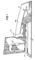
- the stapler apparatus disclosed for which the present invention is embodied for illustration purposes only is a solenoid operated implement such as the commercial desk- type stapler sold in the market as the Swingline Model 6800. It is to be understood that this utilization is only for exemplary purposes and that the stapling apparatus of the present invention is also applicable to a sophisticated finishing stapler head utilized in conjunction with a copying machine.
- the stapling apparatus 11 to which the present invention is embodied comprises a housing 12 containing a stapling head member 13 pivotally movable within the housing, and a base portion 14.
- the base 14 supports a passive clinching anvil 15 which is upwardly inclined at an angle substantially equal to the angle between the stapling head member 13 and the anvil when the stapling head abuts the anvil.
- the base 14 also houses a ribbon roll (not shown) of staple blanks comprising staple blanks 19.
- the base 14 is formed with upstanding ears 20 having mating apertures 21 which are adapted to register with corresponding apertures formed in a lower control portion 24 of the stapling head 13 and in an upper control member 25.
- a pin 26 is disposed within all of the mating apertures to secure the housing 12 and stapling head member 13 to the base 14. The pin 26 also extends through the apertures formed to attach the control portion 24 and control member 25 to one another.
- a suitable spring (not shown) maintains the normal spaced relationship of the stapling head 13 to the anvil 15.
- a support rail 54 adapted to support the interconnected staple blanks 19 unrolled from their supply roll.
- the followers 63, 64 are formed with downwardly formed portions 65, 66 respectively, which are adapted to abut the legs of a formed staple, as will be discussed hereinafter.
- Coil springs 67, 68 secured on one end to the followers 63, 64 respectively, and at their other end to a suitable anchor within the lower control portion 24 urge the respective followers forwardly.
- the stapler is provided with a rear sheath 74 having a front face portion 75 formed with an aperture 76 therein.
- the sheath 74 is secured to the lower control portion 24 by any suitable means.
- the main upper control member 25 includes a forwardly projecting portion 85 and a leaf spring 86 formed with a forwardly projecting tang 87.
- the spring 86 is connected to the control member 25 by being in underlying relationship with respect to inwardly extending bosses 83, 84 formed on the member 25.and by upwardly extending extrusions 88 held within an opening 89 in the spring (see Figure 3).
- the portions 85, 87 are contained within the recess 76 and project forwardly therefrom.
- the tang 87 of the spring 86 is retained within a slot 93 formed in the former 90.
- the former 90 is also formed with an aperture 92 and spaced downwardly projecting portions 94, 95. Between these portions is an intermediate portion 96 which is of shallow arcuate configuration.
- a driver blade 97 Forward of the former 90 is a driver blade 97 which is formed with aperture 99 and a driving element 100.
- the portion 85 of the member 25 also extends through the aperture 92 in the former 90 and the aperture 99 in the driver blade.
- a front sheath 101 forward of the driver blade 97 is a front sheath 101 which is formed with a pair of lateral, oppositely shaped extensions 102, 103.
- Adjacent the driving element 100 of the driver blade 97 is a staple raceway 117 defined by the front end of the rail 54 and the sheath 101 (see Figures 3 and 4).
- the raceway 117 is of sufficient size to accommodate the crown portion of a formed staple but not the full length of an unformed staple element.
- the forward end of the rail 54 adjacent the former 90 constitutes inside forming means 118.
- the former 90 and the driver blade 97 are guided within a raceway formed between the sheath elements 74 and 101.
- a solenoid 119 For actuating the stapler in a stapling action, there is provided a solenoid 119 having a plunger 120 arranged to bear downwardly against the spring 86.
- a suitable circuit is connected to the solenoid 119 to energize the same and may include one or more devices to control the energization upon demand of an operator.
- the structure described above and additional details are found in the above-cited U.S. Patent No. 3,524,575. Only so much of this structure has been included herein that will be necessary to appreciate and understand the inventive improvement embodied in the present invention.
- the ribbon staple blanks 19 are adapted for advanced forward movement along the rail 54 to their most forward position, as shown in Figure 5.
- any one or a number of switches may be utilized to energize the solenoid 119 upon which occurrence the plunger 120 is driven downwardly to move the upper control portion 25 downwardly thereby driving the former 90 also in a downward direction.
- the projecting portions 94, 95 engage and bend the legs of the staple and, as shown in Figure 5, the bending occurs across the extreme forward end of the forming means 118.
- This staple is formed behind the raceway 117 and, until the staple is formed, it cannot pass into and through this raceway. On the other hand, as soon as the staple is so formed, its crown portion is now sufficiently short to pass into the raceway.
- the followers 63 and 64 under force provided by the springs 68 push the legs of the staple involved into the raceway and thus move the entire belt 19 forwardly the diameter of one staple.
- the element 100 of the driver blade 97 will drive this staple through the sheets being stapled.
- the forming means 118 of the support rail 54 normally comprises upstanding walls 150, 151 between which is an open space. As will be discussed hereinafter, with this open space or void immediately behind a staple being formed and driven there is no back up or resistance to repenetration of at lease one of the legs of a formed staple back through a set of sheets. By virtue of the present invention, an insert or integral piece is placed in this void to provide back-up support to a set being stapled so as to offer repenetration resistance as the front sheath 101 does for the staple legs. To this end, a plug member 152 is secured to the forward end of the lower control portion between the walls 150, 151 and extends forwardly to the extreme ends thereof.
- the lower surface of the member 152 has a surface coterminous with the lower edges of the walls 150, 151 so that all these surfaces contact the top surface of the anvil 15 as shown in Figure 5.
- the forward surface of the member 152 forms the rear wall for the raceway 117.
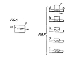
- the clinching grooves 160, 161 as shown in Figures 6 and 7, have their longitudinal axis in parallel but at an angle relative to the bridge portion of a staple in order to prevent the tips of the legs of a staple from interferring with each other during a stapling operation.
- FIGs 7a to 7e there is shown various stages of a deformation of a staple during a stapling operation utilizing the conventional stapler mentioned above.
- the staple has effectively penetrated a 2, 3, 4, or 5 sheet set and the tips are ready to engage the bottoms of the clinching grooves 160, 161.
- the legs of the staple experience a plastic yield and become slightly deformed.
- Figure 7c it is noted that further lowering of the staple provides a greater angular change in the legs.
- Figure 7d it is noted that the shape of each of the legs conforms to the shape of the clinching grooves while the end portion of the legs remain fairly straight.
- the tip of the left leg reenters the paper set to cause repenetration.
- the present invention serves as a remedy to limit the increment of plastic deformation of the left leg at the stage illustrated in Figure 7e. It has been found that repenetration occurs with only the left leg as viewed facing the front of the stapler. Due to the long leg length and the associated offset clinching grooves, the leg tip, after redirection forming in the anvil, is redirected to the rear of the stapler (behind the staple crown) and back up through the paper set. Without a backup to the paper set and the number of sheets being stapled is low, such as comprising 2, 3, 4, or 5 sheets, the leg tips repenetrate the set and protrudes through the top sheet of the set.
- the member 152 is provided within the void defined by the walls 150, 151. As shown in Figure 5, the adjacent surface of the member 152 closes off the raceway 117. In this manner, the left leg of a staple will be prevented from repenetrating the paper set as the legs of the staple deform from the shape shown in Figure 7d to the shape shown in Figure 7e.
- the lower edge of the front sheath 101 offers resistance to the repenetration of the right leg of a staple and the member 152 offers resistance to the repenetration of the left leg.
- the present invention is an improvement of conventional staples which will permit the use of a single sized staple for stapling sets of paper sheets ranging between 2, 3, 4, or 5 sheets per set to sets containing 25 or more sheets.
- Such use envisions the prevention of the repenetration of one or more legs of a staple as being very undesirable in the high quality production of stapled copy sets.
- this use of a single staple for a relatively wide range of thicknesses of paper sets to be stapled is readily available at very minimal cost both in parts and in engineering effort in modifying conventional stapling apparatus.
Landscapes
- Engineering & Computer Science (AREA)
- Mechanical Engineering (AREA)
- Dovetailed Work, And Nailing Machines And Stapling Machines For Wood (AREA)
- Portable Nailing Machines And Staplers (AREA)
- Folding Of Thin Sheet-Like Materials, Special Discharging Devices, And Others (AREA)
Applications Claiming Priority (2)
| Application Number | Priority Date | Filing Date | Title |
|---|---|---|---|
| US06/203,740 US4366924A (en) | 1980-11-03 | 1980-11-03 | Stapler having an abutment for limiting stapler repenetration |
| US203740 | 1980-11-03 |
Publications (2)
| Publication Number | Publication Date |
|---|---|
| EP0051447A1 true EP0051447A1 (fr) | 1982-05-12 |
| EP0051447B1 EP0051447B1 (fr) | 1985-06-26 |
Family
ID=22755135
Family Applications (1)
| Application Number | Title | Priority Date | Filing Date |
|---|---|---|---|
| EP81305109A Expired EP0051447B1 (fr) | 1980-11-03 | 1981-10-28 | Agrafeuse |
Country Status (5)
| Country | Link |
|---|---|
| US (1) | US4366924A (fr) |
| EP (1) | EP0051447B1 (fr) |
| JP (1) | JPS5789571A (fr) |
| CA (1) | CA1161201A (fr) |
| DE (1) | DE3171141D1 (fr) |
Cited By (1)
| Publication number | Priority date | Publication date | Assignee | Title |
|---|---|---|---|---|
| EP0200485A2 (fr) * | 1985-05-01 | 1986-11-05 | The Interlake Companies, Inc. | Dispositif de pliage chevauché pour machine â agrafer |
Families Citing this family (6)
| Publication number | Priority date | Publication date | Assignee | Title |
|---|---|---|---|---|
| US4558391A (en) * | 1983-02-14 | 1985-12-10 | Xerox Corporation | Capacitive discharge drive for electric stapler |
| JPH0435994A (ja) * | 1990-05-31 | 1992-02-06 | Toshiba Corp | 紙葉類綴込み装置および紙葉類綴込み装置を有する画像形成装置 |
| US6237827B1 (en) * | 1998-11-12 | 2001-05-29 | Senco Products, Inc. | Stapler and method for the attachment of steel framing |
| SE525369C2 (sv) * | 2001-09-14 | 2005-02-08 | Isaberg Rapid Ab | Klammerformare i en häftapparat |
| US6925849B2 (en) * | 2002-09-10 | 2005-08-09 | Acco Brands, Inc. | Stapler anvil |
| US20190054605A1 (en) * | 2017-08-18 | 2019-02-21 | Apex Mfg. Co., Ltd. | Staple guiding structure |
Citations (6)
| Publication number | Priority date | Publication date | Assignee | Title |
|---|---|---|---|---|
| US1854647A (en) * | 1929-07-13 | 1932-04-19 | Dennison Mfg Co | Stapling machine |
| US1958739A (en) * | 1932-04-21 | 1934-05-15 | Boston Wire Stitcher Co | Stitching machine |
| US2066157A (en) * | 1933-01-28 | 1936-12-29 | William G Pankonin | Stapling machine |
| US2727234A (en) * | 1952-08-13 | 1955-12-20 | Textile Marking Machine Co Inc | Anvil structure for stapling machines |
| US3524575A (en) * | 1967-03-30 | 1970-08-18 | Swingline Inc | Electric stapling machinne |
| EP0027336A1 (fr) * | 1979-10-01 | 1981-04-22 | Xerox Corporation | Enclume et agrafeuse la comportant |
Family Cites Families (1)
| Publication number | Priority date | Publication date | Assignee | Title |
|---|---|---|---|---|
| US2957174A (en) * | 1957-12-31 | 1960-10-25 | James J Oussani | Stapling device |
-
1980
- 1980-11-03 US US06/203,740 patent/US4366924A/en not_active Expired - Lifetime
-
1981
- 1981-09-30 CA CA000386982A patent/CA1161201A/fr not_active Expired
- 1981-10-07 JP JP56160050A patent/JPS5789571A/ja active Granted
- 1981-10-28 EP EP81305109A patent/EP0051447B1/fr not_active Expired
- 1981-10-28 DE DE8181305109T patent/DE3171141D1/de not_active Expired
Patent Citations (6)
| Publication number | Priority date | Publication date | Assignee | Title |
|---|---|---|---|---|
| US1854647A (en) * | 1929-07-13 | 1932-04-19 | Dennison Mfg Co | Stapling machine |
| US1958739A (en) * | 1932-04-21 | 1934-05-15 | Boston Wire Stitcher Co | Stitching machine |
| US2066157A (en) * | 1933-01-28 | 1936-12-29 | William G Pankonin | Stapling machine |
| US2727234A (en) * | 1952-08-13 | 1955-12-20 | Textile Marking Machine Co Inc | Anvil structure for stapling machines |
| US3524575A (en) * | 1967-03-30 | 1970-08-18 | Swingline Inc | Electric stapling machinne |
| EP0027336A1 (fr) * | 1979-10-01 | 1981-04-22 | Xerox Corporation | Enclume et agrafeuse la comportant |
Cited By (2)
| Publication number | Priority date | Publication date | Assignee | Title |
|---|---|---|---|---|
| EP0200485A2 (fr) * | 1985-05-01 | 1986-11-05 | The Interlake Companies, Inc. | Dispositif de pliage chevauché pour machine â agrafer |
| EP0200485A3 (fr) * | 1985-05-01 | 1988-10-05 | The Interlake Companies, Inc. | Dispositif de pliage chevauché pour machine â agrafer |
Also Published As
| Publication number | Publication date |
|---|---|
| JPH0126825B2 (fr) | 1989-05-25 |
| CA1161201A (fr) | 1984-01-31 |
| EP0051447B1 (fr) | 1985-06-26 |
| DE3171141D1 (en) | 1985-08-01 |
| JPS5789571A (en) | 1982-06-03 |
| US4366924A (en) | 1983-01-04 |
Similar Documents
| Publication | Publication Date | Title |
|---|---|---|
| US5516025A (en) | Stapler having a clinching mechanism | |
| EP0530857B1 (fr) | Enclume | |
| US6036074A (en) | Staple clinching mechanism in stapler | |
| US4542844A (en) | Staple forming and driving machine | |
| US4378085A (en) | Stapler apparatus having a mechanism for bending and cutting staple legs in accordance with the thickness of the work piece | |
| EP0636058B1 (fr) | Cassette destinee a etre utilisee avec une agrafeuse | |
| US20080054042A1 (en) | Stapler | |
| US20040020963A1 (en) | Adjustable stapler and methods associated therewith | |
| JP4082251B2 (ja) | ステープラーのクリンチャ装置 | |
| US5038992A (en) | Structure of stapler | |
| EP1711314B1 (fr) | Agrafeuse | |
| EP0027336B1 (fr) | Enclume et agrafeuse la comportant | |
| WO1995019248A1 (fr) | Agrafeuse pneumatique ou electrique | |
| EP0039560A1 (fr) | Cartouche pour agrafeuse | |
| WO1998047669A1 (fr) | Agrafeuse avec guidage interne des branches d'agrafe | |
| US4366924A (en) | Stapler having an abutment for limiting stapler repenetration | |
| WO2006009015A1 (fr) | Agrafeuse et cartouche pour agrafeuse | |
| US5692667A (en) | Document positioning member for a stapler | |
| US4610386A (en) | Stapler having a variable stop member for limiting stapling stroke and staple leg length | |
| EP1582323B1 (fr) | Mecanisme de guidage de pattes d'agrafes | |
| US2977599A (en) | Vertical drop stapling machine | |
| JPH0118297Y2 (fr) | ||
| JPH08174445A (ja) | ステープラー | |
| JP2727169B2 (ja) | ステープラー | |
| JPH09109062A (ja) | ステープラ |
Legal Events
| Date | Code | Title | Description |
|---|---|---|---|
| PUAI | Public reference made under article 153(3) epc to a published international application that has entered the european phase |
Free format text: ORIGINAL CODE: 0009012 |
|
| AK | Designated contracting states |
Designated state(s): DE GB |
|
| 17P | Request for examination filed |
Effective date: 19821004 |
|
| GRAA | (expected) grant |
Free format text: ORIGINAL CODE: 0009210 |
|
| AK | Designated contracting states |
Designated state(s): DE GB |
|
| REF | Corresponds to: |
Ref document number: 3171141 Country of ref document: DE Date of ref document: 19850801 |
|
| PLBE | No opposition filed within time limit |
Free format text: ORIGINAL CODE: 0009261 |
|
| STAA | Information on the status of an ep patent application or granted ep patent |
Free format text: STATUS: NO OPPOSITION FILED WITHIN TIME LIMIT |
|
| 26N | No opposition filed | ||
| PGFP | Annual fee paid to national office [announced via postgrant information from national office to epo] |
Ref country code: DE Payment date: 20001023 Year of fee payment: 20 |
|
| PGFP | Annual fee paid to national office [announced via postgrant information from national office to epo] |
Ref country code: GB Payment date: 20001025 Year of fee payment: 20 |
|
| PG25 | Lapsed in a contracting state [announced via postgrant information from national office to epo] |
Ref country code: GB Free format text: LAPSE BECAUSE OF EXPIRATION OF PROTECTION Effective date: 20011027 |
|
| REG | Reference to a national code |
Ref country code: GB Ref legal event code: PE20 Effective date: 20011027 |