EP0051445A2 - A floor grating - Google Patents
A floor grating Download PDFInfo
- Publication number
- EP0051445A2 EP0051445A2 EP81305104A EP81305104A EP0051445A2 EP 0051445 A2 EP0051445 A2 EP 0051445A2 EP 81305104 A EP81305104 A EP 81305104A EP 81305104 A EP81305104 A EP 81305104A EP 0051445 A2 EP0051445 A2 EP 0051445A2
- Authority
- EP
- European Patent Office
- Prior art keywords
- bars
- longitudinal bars
- slots
- longitudinal
- transverse
- Prior art date
- Legal status (The legal status is an assumption and is not a legal conclusion. Google has not performed a legal analysis and makes no representation as to the accuracy of the status listed.)
- Granted
Links
Images
Classifications
-
- E—FIXED CONSTRUCTIONS
- E04—BUILDING
- E04C—STRUCTURAL ELEMENTS; BUILDING MATERIALS
- E04C2/00—Building elements of relatively thin form for the construction of parts of buildings, e.g. sheet materials, slabs, or panels
- E04C2/30—Building elements of relatively thin form for the construction of parts of buildings, e.g. sheet materials, slabs, or panels characterised by the shape or structure
- E04C2/42—Gratings; Grid-like panels
- E04C2/421—Gratings; Grid-like panels made of bar-like elements, e.g. bars discontinuous in one direction
- E04C2/422—Gratings; Grid-like panels made of bar-like elements, e.g. bars discontinuous in one direction with continuous bars connecting at crossing points of the grid pattern
- E04C2/423—Gratings; Grid-like panels made of bar-like elements, e.g. bars discontinuous in one direction with continuous bars connecting at crossing points of the grid pattern with notches
-
- B—PERFORMING OPERATIONS; TRANSPORTING
- B21—MECHANICAL METAL-WORKING WITHOUT ESSENTIALLY REMOVING MATERIAL; PUNCHING METAL
- B21D—WORKING OR PROCESSING OF SHEET METAL OR METAL TUBES, RODS OR PROFILES WITHOUT ESSENTIALLY REMOVING MATERIAL; PUNCHING METAL
- B21D47/00—Making rigid structural elements or units, e.g. honeycomb structures
- B21D47/005—Making gratings
Definitions
- THIS invention relates to a method for forming floor gratings which are suitable for supporting substantial loads off the ground, and to gratings formed by the method.
- the invention relates to gratings of the type having two sets of parallel bars extending at right angles to one another to form a load supporting grid arrangement. Such gratings are commonly used in elevated walkways etc.
- the two sets of bars will be referred to as longitudinal and transverse bars respectively, but this is not to be taken in any way as limiting the direction in which either set may extend in an assembled grating.
- the longitudinal bars are deformed outwardly in those regions lying between the legs of the U-shaped transverse bars to prevent their removal from the slots.
- the transverse bars are also deformed above the longitudinal bars to provide further insurance against withdrawal from the slots.
- Deformation of the longitudinal bars is achieved by means of a pressing operation.
- the bed plate of the press used is shaped to deform the transverse bars in the region of the edges of the slots to cause these edges to overlap the longitudinal bars which have been received in the slots.
- Such deformation has the effect of reducing the compressive strength of the upper edges of the transverse bars.
- the fact that the whole depth of the longitudinal bars is received within the slots formed in the transverse bars means that the uppermost edges of the steel of the transverse bars are unable to take any compressive loading at all, since there is no continuity of material above the level of the longitudinal bars.
- a further disadvantage of the grating described in US-PS 1,620,846 lies in the protection of the grating against corrosion once-it has been fabricated. Sharp bends etc. should be avoided if galvanising or painting operations are contemplated,to ensure that a uniform coating is achieved.
- the deformation employed in the grating shown in the US specification will give rise to sharp edges at the sides of the slots, and consequently to difficulty in applying the necessary coating to these critical areas of the steel to protect it.
- the invention provides a method of forming a floor grating having a plurality of inverted U-shaped transverse bars and a plurality of longitudinal bars, the longitudinal bars being fitted in slots formed in the apices of the U-shaped bars and being deformed in those regions lying within the U-shapes, characterised by the steps of forming the transverse bars by folding them from flat plates and by deforming the longitudinal bars without cutting into the material of the longitudinal bars, so that their depth is substantially the same in those regions lying within the U-shapes as in those regions lying outside the U-shapes.
- the longitudinal bars are press-fitted into the slots.
- the slots may be formed in the apices of the transverse bars by punching prior to folding the flat plate.
- the longitudinal bars may be deformed by applying a lateral force to the material of each longitudinal bar in those regions lying within the U-shapes to produce a bulge on one side of the plane of the longitudinal bar.
- a floor grating having a pluralityof inverted U-shaped transverse bars and a plurality of longitudinal bars, the longitudinal bars being fitted in slots formed in the apices of the U-shaped bars and being deformed in those regions lying within the U-shapes, characterised in that the transverse bars are formed by folding them from flat plates, and in that the longitudinal bars are deformed without cutting into the material of the longitudinal bars so that their depth is substantially the same in those regions lying within the U-shapes as in those regions lying outside the U-shapes.
- each longitudinal bar projects above the level of the apices of the transverse bars.
- the section of finished grating shown in Figure 1 is made up of transverse bearer bars 1 and longitudinal bars 2.
- Each transverse bearer bar has a U-shaped cross-section, as can be most clearly seen in Figures 3 and 5.
- the U-shape in fact approximates to'a V-shape, but in practice there will always be some radius at the apex of the section, and the section is accordingly described as U-shape.
- the longitudinal bars 2 have castellated upper edges. This serves as an aid in the prevention of slippage on the grating. It will be appreciated that gratings of the type under consideration are often used at substantial elevations, and that slippage of a person walking over the grating could have disasterous consequences.
- the transverse bearer bars 1 are formed in the following manner: Strips of flat plate are passed beneath a punch, which is operated to punch a series of spaced transverse slots 5 from the plates across their central axes. One such plate is illustrated in Figure 4 after the punching operation.
- the plates are then folded to the shape shown in Figure 5 about the central axis.
- the resulting U-section then has a series of spaced slots 5 located along its apex.
- transverse bearer bars 1 are then arranged in a spaced parallel relationship with the corresponding slots in each bar directed upwardly and in alignment with one another, ready to receive longitudinal bars 2 to form the grating.
- the longitudinal bars 2 are lengths of flat bar.
- the bars 2, prior to their insertion into the slots, are castellated along their upper edges to provide a better foothold for persons using the grating.
- Each longitudinal bar 2 is then forced as a tight press-fit into one row of aligned slots.
- the dimensions of the slots are such that when the plate has been folded to produce the transverse bearer bars, the depth of the slots is not sufficient to receive the full depth of the longitudinal bars.
- the castellated portion of each longitudinal bar protrudes above the level of the apices of the transverse bars, as can clearly be seen in Figure 3.
- the tightness of the fit may result in the upper edge of the steel of the transverse bars being subjected to compression, i.e. a "prestressing" of these upper edges takes place. A slight bowing of the transverse bars may even take place.
- gratings manufactured according to the method of the present invention have a weight some 30% less than comparable gratings which exhibit similar strength. This is mainly due to the method of formation of the transverse bearer bars. It has been found that a suitable thickness of plate for use in preparing the transverse bearer bars is 3mm for most applications. Such plate is not excessive in weight, and is easily punched and handled.
- the grating described also allows for a better protective coating to be applied to the finished grating than does the grating of the US patent.
- the tightness of the fit in the slots also acts to lessen the likelihood of relative movement between the two sets of bars, with less resulting abrasion between bars and destruction of a coating which has been applied.
- a further, readily ascertainable advantage of the method of the present invention over the disclosure of the United States patent lies in the punching operation to form the slots in the apices of the transverse bars. It will be appreciated that it is easier to punch slots from a flat plate than it is to punch or cut the slots laterally from the apex of a steel angle section.
- the present invention is applicable to gratings intended for almost any span. With steel sections, the designer is limited by the angle sections available. With increasing angle size, there will be increasing fabrication difficulties. Gratings formed according to the present invention can be designed to suit a wide range of spans, by,.for example, increasing or decreasing the length of the legs of the transverse bars, as the case may be.
Abstract
Description
- THIS invention relates to a method for forming floor gratings which are suitable for supporting substantial loads off the ground, and to gratings formed by the method. In particular, the invention relates to gratings of the type having two sets of parallel bars extending at right angles to one another to form a load supporting grid arrangement. Such gratings are commonly used in elevated walkways etc.
- In this specification, the two sets of bars will be referred to as longitudinal and transverse bars respectively, but this is not to be taken in any way as limiting the direction in which either set may extend in an assembled grating.
- It has already been proposed to use inverted U-shaped members for the transverse bars (see United States Patent No. 1,620,846 to A.E. Wells), with slots being cut in the apices of these members to receive portions of the longitudinal bars. In United States Patent No. 1,620,846, the preferred shape of the longitudinal bars is a square section. According to that patent, once a series of transverse bars have been arranged in parallel with their slots aligned, the longitudinal bars are dropped loosely into the slots to form a grid. The slots are made deep enough to receive the full height of the longitudinal bars.
- Once in position in the slots, the longitudinal bars are deformed outwardly in those regions lying between the legs of the U-shaped transverse bars to prevent their removal from the slots. The transverse bars are also deformed above the longitudinal bars to provide further insurance against withdrawal from the slots.
- There are a number of problems associated with the manufacture of a grating of the type disclosed in USP 1,620,846. In this patent, the inverted U-shaped members are formed by forcing the legs of an angle section member toward one another. In view of the substantial strength of most standard angle sections available, this operation is not easily achieved. The difficulty is increased in that standard angle sections have a finite radius in the fillet of the section which provides some resistance to bending the legs of the section towards one another.
- Another problem is encountered in the provision of the slots in the apices of the transverse members. It is suggested in USP 1,620,846 that this be achieved by a lateral punching operation, or by cutting. It will be appreciated that the fillet of the angle.section will provide resistance to this operation as well. The very nature of the angle section renders the punching operation at the apex a difficult one.
- Deformation of the longitudinal bars is achieved by means of a pressing operation. The bed plate of the press used is shaped to deform the transverse bars in the region of the edges of the slots to cause these edges to overlap the longitudinal bars which have been received in the slots. Such deformation has the effect of reducing the compressive strength of the upper edges of the transverse bars. Furthermore, the fact that the whole depth of the longitudinal bars is received within the slots formed in the transverse bars means that the uppermost edges of the steel of the transverse bars are unable to take any compressive loading at all, since there is no continuity of material above the level of the longitudinal bars.
- A further disadvantage of the grating described in US-PS 1,620,846 lies in the protection of the grating against corrosion once-it has been fabricated. Sharp bends etc. should be avoided if galvanising or painting operations are contemplated,to ensure that a uniform coating is achieved. The deformation employed in the grating shown in the US specification will give rise to sharp edges at the sides of the slots, and consequently to difficulty in applying the necessary coating to these critical areas of the steel to protect it.
- Nevertheless, the use of U-shaped transverse members has been shown to have certain advantages as regards weight savings. It is accordingly an object of the present invention to provide a method of manufacture for a grating employing such members, which method does not suffer from the disadvantages set out above in respect of the known gratings.
- The invention provides a method of forming a floor grating having a plurality of inverted U-shaped transverse bars and a plurality of longitudinal bars, the longitudinal bars being fitted in slots formed in the apices of the U-shaped bars and being deformed in those regions lying within the U-shapes, characterised by the steps of forming the transverse bars by folding them from flat plates and by deforming the longitudinal bars without cutting into the material of the longitudinal bars, so that their depth is substantially the same in those regions lying within the U-shapes as in those regions lying outside the U-shapes.
- Preferably, the longitudinal bars are press-fitted into the slots.
- The slots may be formed in the apices of the transverse bars by punching prior to folding the flat plate.
- The longitudinal bars may be deformed by applying a lateral force to the material of each longitudinal bar in those regions lying within the U-shapes to produce a bulge on one side of the plane of the longitudinal bar.
- Conveniently, adjacent longitudinal. bars in each U-shape.are deformed simultaneously by forcing between them a pressing head having an operative width greater than the clear spacing between the longitudinal bars.
- Another aspect of the invention provides a floor grating having a pluralityof inverted U-shaped transverse bars and a plurality of longitudinal bars, the longitudinal bars being fitted in slots formed in the apices of the U-shaped bars and being deformed in those regions lying within the U-shapes, characterised in that the transverse bars are formed by folding them from flat plates, and in that the longitudinal bars are deformed without cutting into the material of the longitudinal bars so that their depth is substantially the same in those regions lying within the U-shapes as in those regions lying outside the U-shapes.
- Preferably, a portion of each longitudinal bar projects above the level of the apices of the transverse bars.
- The invention will now be further described, by way of example, with reference to the accompanying drawings in which
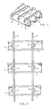
- Figure 1 is a perspective view of a grating according to the invention;
- Figure 2 is an underneath view of the grating shown in Figure 1; and
- Figure 3 is a side view of the grating shown in Figure 1.
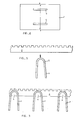
- Figure 4 shows a plan view of a plate after a punching operation to form slots across the central axis; and
- Figure 5 shows an end view of a transverse bar after punching and - folding along the central axis, and a longitudinal bar castellated along its upper edge prior to insertion in a slot in the transverse bar.
- The section of finished grating shown in Figure 1 is made up of
transverse bearer bars 1 andlongitudinal bars 2. Each transverse bearer bar has a U-shaped cross-section, as can be most clearly seen in Figures 3 and 5. The U-shape in fact approximates to'a V-shape, but in practice there will always be some radius at the apex of the section, and the section is accordingly described as U-shape. Furthermore, it is preferred to have a slightly rounded apex, for it will be appreciated that it could be uncomfortable on the feet of a person walking over the grating if the apices of the transverse bearer bars are too sharply pointed. - It will also be seen in the drawings that the
longitudinal bars 2 have castellated upper edges. This serves as an aid in the prevention of slippage on the grating. It will be appreciated that gratings of the type under consideration are often used at substantial elevations, and that slippage of a person walking over the grating could have disasterous consequences. - The
transverse bearer bars 1 are formed in the following manner: Strips of flat plate are passed beneath a punch, which is operated to punch a series of spacedtransverse slots 5 from the plates across their central axes. One such plate is illustrated in Figure 4 after the punching operation. - The plates are then folded to the shape shown in Figure 5 about the central axis. The resulting U-section then has a series of spaced
slots 5 located along its apex. - The
transverse bearer bars 1 are then arranged in a spaced parallel relationship with the corresponding slots in each bar directed upwardly and in alignment with one another, ready to receivelongitudinal bars 2 to form the grating. - The
longitudinal bars 2 are lengths of flat bar. Thebars 2, prior to their insertion into the slots, are castellated along their upper edges to provide a better foothold for persons using the grating. - Each
longitudinal bar 2 is then forced as a tight press-fit into one row of aligned slots. It should be noted that the dimensions of the slots are such that when the plate has been folded to produce the transverse bearer bars, the depth of the slots is not sufficient to receive the full depth of the longitudinal bars. The castellated portion of each longitudinal bar protrudes above the level of the apices of the transverse bars, as can clearly be seen in Figure 3. As the longitudinal bars are forced into the slots in the transverse bars, the tightness of the fit may result in the upper edge of the steel of the transverse bars being subjected to compression, i.e. a "prestressing" of these upper edges takes place. A slight bowing of the transverse bars may even take place. It will be appreciated that this acts to increase the overall strength of the assembled grating. When compared to the grating disclosed in US patent No. 1,620,846, it will be seen that the continuity of material at the level of the apices of the transverse bars in the present invention makes for greater strength in compression along the upper edges of the transverse bars than does the lack of continuity of material in the earlier disclosure. - Once all the longitudinal bars have been forced into their slots, the undersides of these bars are deformed to prevent their withdrawal from the slots. Referring to Figure 2, it will be seen that the longitudinal bars are deformed by causing them to bulge sideways. In practice, a single pressing head having an operative thickness greater than the spacing of the longitudinal bars is caused to act between the two adjacent longitudinal bars of a pair in the space between the legs of each U-section to cause the bars to bulge in opposite directions. In view of the rapidity and simplicity of the deforming operation, it is desirable to deform the longitudinal bars in the region between the legs_ of each transverse bearer bar, so as to provide greater rigidity to the whole structure.
- It has been found that gratings manufactured according to the method of the present invention have a weight some 30% less than comparable gratings which exhibit similar strength. This is mainly due to the method of formation of the transverse bearer bars. It has been found that a suitable thickness of plate for use in preparing the transverse bearer bars is 3mm for most applications. Such plate is not excessive in weight, and is easily punched and handled.
- In practice, it has been found necessary in some applications to fold the legs of the transverse bars into almost parallel alignment with one another. This configuration allows lumps of coal etc. to fall freely between the transverse bars without becoming jammed. It will be appreciated that this would be difficult to achieve if the transverse bearer bars were formed from angle section steel as suggested in US patent No. 1,620,846, in view of the difficulty in bending the legs of the angle towards one another.
- The grating described also allows for a better protective coating to be applied to the finished grating than does the grating of the US patent. The fact that no complex crimping operations take place along the apices of the transverse bars, with no resulting sharp edges, allows for greater uniformity of coating of, say zinc, in a galvanising process.
- The tightness of the fit in the slots also acts to lessen the likelihood of relative movement between the two sets of bars, with less resulting abrasion between bars and destruction of a coating which has been applied.
- A further, readily ascertainable advantage of the method of the present invention over the disclosure of the United States patent lies in the punching operation to form the slots in the apices of the transverse bars. It will be appreciated that it is easier to punch slots from a flat plate than it is to punch or cut the slots laterally from the apex of a steel angle section.
- Furthermore, the present invention is applicable to gratings intended for almost any span. With steel sections, the designer is limited by the angle sections available. With increasing angle size, there will be increasing fabrication difficulties. Gratings formed according to the present invention can be designed to suit a wide range of spans, by,.for example, increasing or decreasing the length of the legs of the transverse bars, as the case may be.
Claims (10)
Priority Applications (1)
| Application Number | Priority Date | Filing Date | Title |
|---|---|---|---|
| AT81305104T ATE15456T1 (en) | 1980-10-28 | 1981-10-28 | FLOOR GRILLING. |
Applications Claiming Priority (2)
| Application Number | Priority Date | Filing Date | Title |
|---|---|---|---|
| ZA806614 | 1980-10-28 | ||
| ZA806614 | 1980-10-28 |
Publications (3)
| Publication Number | Publication Date |
|---|---|
| EP0051445A2 true EP0051445A2 (en) | 1982-05-12 |
| EP0051445A3 EP0051445A3 (en) | 1982-08-04 |
| EP0051445B1 EP0051445B1 (en) | 1985-09-11 |
Family
ID=25575003
Family Applications (1)
| Application Number | Title | Priority Date | Filing Date |
|---|---|---|---|
| EP81305104A Expired EP0051445B1 (en) | 1980-10-28 | 1981-10-28 | A floor grating |
Country Status (6)
| Country | Link |
|---|---|
| EP (1) | EP0051445B1 (en) |
| JP (1) | JPS57108358A (en) |
| AT (1) | ATE15456T1 (en) |
| AU (1) | AU550546B2 (en) |
| DE (1) | DE3172255D1 (en) |
| NZ (1) | NZ198765A (en) |
Cited By (4)
| Publication number | Priority date | Publication date | Assignee | Title |
|---|---|---|---|---|
| GB2155075A (en) * | 1984-02-25 | 1985-09-18 | Norton Eng Alloys Co Ltd | Deck-forming member |
| US5174707A (en) * | 1989-06-30 | 1992-12-29 | Ohbayashi Corp. | Three-dimensional manufacturing and assembly plant |
| GB2308396A (en) * | 1995-12-20 | 1997-06-25 | Kennedy Lionweld Ltd | Grating and method for it's manufacture |
| WO2000003104A1 (en) * | 1998-07-10 | 2000-01-20 | Owen Lyell Livingston | Modular walkway |
Families Citing this family (1)
| Publication number | Priority date | Publication date | Assignee | Title |
|---|---|---|---|---|
| JPS61147806U (en) * | 1985-03-06 | 1986-09-11 |
Citations (3)
| Publication number | Priority date | Publication date | Assignee | Title |
|---|---|---|---|---|
| US1620846A (en) * | 1921-10-31 | 1927-03-15 | Arthur E Wells | Grating |
| US1750039A (en) * | 1928-06-04 | 1930-03-11 | Feltes Peter Emil | Grating |
| NL7806980A (en) * | 1978-06-28 | 1980-01-03 | Gouda Holland Holdings Sa | Detachable joint for ceiling grid construction - fits between intersecting channel sections with locking lugs and openings above section bottoms |
-
1981
- 1981-10-27 JP JP56170862A patent/JPS57108358A/en active Granted
- 1981-10-27 AU AU76859/81A patent/AU550546B2/en not_active Ceased
- 1981-10-27 NZ NZ198765A patent/NZ198765A/en unknown
- 1981-10-28 DE DE8181305104T patent/DE3172255D1/en not_active Expired
- 1981-10-28 EP EP81305104A patent/EP0051445B1/en not_active Expired
- 1981-10-28 AT AT81305104T patent/ATE15456T1/en not_active IP Right Cessation
Patent Citations (3)
| Publication number | Priority date | Publication date | Assignee | Title |
|---|---|---|---|---|
| US1620846A (en) * | 1921-10-31 | 1927-03-15 | Arthur E Wells | Grating |
| US1750039A (en) * | 1928-06-04 | 1930-03-11 | Feltes Peter Emil | Grating |
| NL7806980A (en) * | 1978-06-28 | 1980-01-03 | Gouda Holland Holdings Sa | Detachable joint for ceiling grid construction - fits between intersecting channel sections with locking lugs and openings above section bottoms |
Cited By (4)
| Publication number | Priority date | Publication date | Assignee | Title |
|---|---|---|---|---|
| GB2155075A (en) * | 1984-02-25 | 1985-09-18 | Norton Eng Alloys Co Ltd | Deck-forming member |
| US5174707A (en) * | 1989-06-30 | 1992-12-29 | Ohbayashi Corp. | Three-dimensional manufacturing and assembly plant |
| GB2308396A (en) * | 1995-12-20 | 1997-06-25 | Kennedy Lionweld Ltd | Grating and method for it's manufacture |
| WO2000003104A1 (en) * | 1998-07-10 | 2000-01-20 | Owen Lyell Livingston | Modular walkway |
Also Published As
| Publication number | Publication date |
|---|---|
| EP0051445B1 (en) | 1985-09-11 |
| JPS57108358A (en) | 1982-07-06 |
| JPH0149864B2 (en) | 1989-10-26 |
| EP0051445A3 (en) | 1982-08-04 |
| AU550546B2 (en) | 1986-03-27 |
| AU7685981A (en) | 1982-05-06 |
| ATE15456T1 (en) | 1985-09-15 |
| DE3172255D1 (en) | 1985-10-17 |
| NZ198765A (en) | 1984-03-30 |
Similar Documents
| Publication | Publication Date | Title |
|---|---|---|
| DE19852877B4 (en) | Panel grounding contact | |
| SE447144B (en) | TIMBER BALK AND SETS AND RESOURCES FOR ITS MANUFACTURING | |
| DE20307769U1 (en) | joist hanger | |
| DE3603836A1 (en) | EDGE-WINDED SHEET PACKAGE, METHOD AND CUT-IN STRIPES FOR THEIR PRODUCTION | |
| EP0051445B1 (en) | A floor grating | |
| DE69926772T2 (en) | RAIL RETAINING DEVICE | |
| DE2601405A1 (en) | CONNECTOR | |
| DE4400682A1 (en) | Rail with fire classification for suspended ceilings | |
| US9212504B1 (en) | Fence post system, construction, and method | |
| WO2016193023A1 (en) | Framework platform element, in particular for scaffolding | |
| SE456831B (en) | FOLDED CONNECTION BODY FOR THE MANUFACTURING OF TRAY BANKS AND USED THEREOF | |
| US4126980A (en) | Metal grating | |
| CA1182976A (en) | Floor grating | |
| US3295405A (en) | Grip plate for wooden truss members | |
| US3364805A (en) | Connector plate | |
| EP3997285A1 (en) | Connecting device | |
| CH623395A5 (en) | Grating | |
| DE10017156B4 (en) | Conveyor chain for a conveyor of a disk-laying device of a slicing machine | |
| US5884773A (en) | Carrier strip and method of its manufacturing | |
| WO1993015287A1 (en) | Lattice girder | |
| EP0611636A1 (en) | Apparatus for cutting a product into slices and method for manufacturing such an apparatus | |
| GB2121848A (en) | Wall studs and connectors therefor | |
| EP3556971A1 (en) | Transport anchor | |
| EP0318450A1 (en) | An element for the construction of lattice webs for girders and like structural members, and a method for manufacturing such an element | |
| DE10120788A1 (en) | Packaging element has two connecting pieces, extensible section with protuberance and sloping section. |
Legal Events
| Date | Code | Title | Description |
|---|---|---|---|
| PUAI | Public reference made under article 153(3) epc to a published international application that has entered the european phase |
Free format text: ORIGINAL CODE: 0009012 |
|
| AK | Designated contracting states |
Designated state(s): AT BE CH DE FR GB IT LU NL SE |
|
| PUAL | Search report despatched |
Free format text: ORIGINAL CODE: 0009013 |
|
| AK | Designated contracting states |
Designated state(s): AT BE CH DE FR GB IT LU NL SE |
|
| RAP1 | Party data changed (applicant data changed or rights of an application transferred) |
Owner name: OWEN LYELL LIVINGSTON |
|
| 17P | Request for examination filed |
Effective date: 19830126 |
|
| ITF | It: translation for a ep patent filed |
Owner name: JACOBACCI & PERANI S.P.A. |
|
| GRAA | (expected) grant |
Free format text: ORIGINAL CODE: 0009210 |
|
| AK | Designated contracting states |
Designated state(s): AT BE CH DE FR GB IT LI LU NL SE |
|
| REF | Corresponds to: |
Ref document number: 15456 Country of ref document: AT Date of ref document: 19850915 Kind code of ref document: T |
|
| REF | Corresponds to: |
Ref document number: 3172255 Country of ref document: DE Date of ref document: 19851017 |
|
| ET | Fr: translation filed | ||
| PLBE | No opposition filed within time limit |
Free format text: ORIGINAL CODE: 0009261 |
|
| STAA | Information on the status of an ep patent application or granted ep patent |
Free format text: STATUS: NO OPPOSITION FILED WITHIN TIME LIMIT |
|
| 26N | No opposition filed | ||
| PGFP | Annual fee paid to national office [announced via postgrant information from national office to epo] |
Ref country code: BE Payment date: 19920812 Year of fee payment: 12 |
|
| PGFP | Annual fee paid to national office [announced via postgrant information from national office to epo] |
Ref country code: FR Payment date: 19920814 Year of fee payment: 12 |
|
| PGFP | Annual fee paid to national office [announced via postgrant information from national office to epo] |
Ref country code: SE Payment date: 19920831 Year of fee payment: 12 |
|
| PGFP | Annual fee paid to national office [announced via postgrant information from national office to epo] |
Ref country code: LU Payment date: 19921007 Year of fee payment: 12 |
|
| PGFP | Annual fee paid to national office [announced via postgrant information from national office to epo] |
Ref country code: GB Payment date: 19921016 Year of fee payment: 12 |
|
| PGFP | Annual fee paid to national office [announced via postgrant information from national office to epo] |
Ref country code: AT Payment date: 19921028 Year of fee payment: 12 |
|
| ITTA | It: last paid annual fee | ||
| PGFP | Annual fee paid to national office [announced via postgrant information from national office to epo] |
Ref country code: NL Payment date: 19921031 Year of fee payment: 12 |
|
| PGFP | Annual fee paid to national office [announced via postgrant information from national office to epo] |
Ref country code: DE Payment date: 19921210 Year of fee payment: 12 |
|
| PGFP | Annual fee paid to national office [announced via postgrant information from national office to epo] |
Ref country code: CH Payment date: 19930129 Year of fee payment: 12 |
|
| EPTA | Lu: last paid annual fee | ||
| PG25 | Lapsed in a contracting state [announced via postgrant information from national office to epo] |
Ref country code: LU Free format text: LAPSE BECAUSE OF NON-PAYMENT OF DUE FEES Effective date: 19931028 Ref country code: GB Effective date: 19931028 Ref country code: AT Effective date: 19931028 |
|
| PG25 | Lapsed in a contracting state [announced via postgrant information from national office to epo] |
Ref country code: SE Effective date: 19931029 |
|
| PG25 | Lapsed in a contracting state [announced via postgrant information from national office to epo] |
Ref country code: LI Effective date: 19931031 Ref country code: CH Effective date: 19931031 Ref country code: BE Effective date: 19931031 |
|
| BERE | Be: lapsed |
Owner name: OWEN LYELL LIVINGSTON Effective date: 19931031 |
|
| PG25 | Lapsed in a contracting state [announced via postgrant information from national office to epo] |
Ref country code: NL Effective date: 19940501 |
|
| NLV4 | Nl: lapsed or anulled due to non-payment of the annual fee | ||
| GBPC | Gb: european patent ceased through non-payment of renewal fee |
Effective date: 19931028 |
|
| PG25 | Lapsed in a contracting state [announced via postgrant information from national office to epo] |
Ref country code: FR Effective date: 19940630 |
|
| REG | Reference to a national code |
Ref country code: CH Ref legal event code: PL |
|
| PG25 | Lapsed in a contracting state [announced via postgrant information from national office to epo] |
Ref country code: DE Effective date: 19940701 |
|
| REG | Reference to a national code |
Ref country code: FR Ref legal event code: ST |
|
| EUG | Se: european patent has lapsed |
Ref document number: 81305104.2 Effective date: 19940510 |