EP0051300B1 - Method for making an exhaust valve for a diesel engine - Google Patents
Method for making an exhaust valve for a diesel engine Download PDFInfo
- Publication number
- EP0051300B1 EP0051300B1 EP81109361A EP81109361A EP0051300B1 EP 0051300 B1 EP0051300 B1 EP 0051300B1 EP 81109361 A EP81109361 A EP 81109361A EP 81109361 A EP81109361 A EP 81109361A EP 0051300 B1 EP0051300 B1 EP 0051300B1
- Authority
- EP
- European Patent Office
- Prior art keywords
- layer
- ceramic
- ceramics
- valve
- seat
- Prior art date
- Legal status (The legal status is an assumption and is not a legal conclusion. Google has not performed a legal analysis and makes no representation as to the accuracy of the status listed.)
- Expired
Links
Images
Classifications
-
- F—MECHANICAL ENGINEERING; LIGHTING; HEATING; WEAPONS; BLASTING
- F01—MACHINES OR ENGINES IN GENERAL; ENGINE PLANTS IN GENERAL; STEAM ENGINES
- F01L—CYCLICALLY OPERATING VALVES FOR MACHINES OR ENGINES
- F01L3/00—Lift-valve, i.e. cut-off apparatus with closure members having at least a component of their opening and closing motion perpendicular to the closing faces; Parts or accessories thereof
- F01L3/22—Valve-seats not provided for in preceding subgroups of this group; Fixing of valve-seats
-
- F—MECHANICAL ENGINEERING; LIGHTING; HEATING; WEAPONS; BLASTING
- F01—MACHINES OR ENGINES IN GENERAL; ENGINE PLANTS IN GENERAL; STEAM ENGINES
- F01L—CYCLICALLY OPERATING VALVES FOR MACHINES OR ENGINES
- F01L3/00—Lift-valve, i.e. cut-off apparatus with closure members having at least a component of their opening and closing motion perpendicular to the closing faces; Parts or accessories thereof
- F01L3/02—Selecting particular materials for valve-members or valve-seats; Valve-members or valve-seats composed of two or more materials
- F01L3/04—Coated valve members or valve-seats
-
- F—MECHANICAL ENGINEERING; LIGHTING; HEATING; WEAPONS; BLASTING
- F02—COMBUSTION ENGINES; HOT-GAS OR COMBUSTION-PRODUCT ENGINE PLANTS
- F02F—CYLINDERS, PISTONS OR CASINGS, FOR COMBUSTION ENGINES; ARRANGEMENTS OF SEALINGS IN COMBUSTION ENGINES
- F02F7/00—Casings, e.g. crankcases
- F02F7/0085—Materials for constructing engines or their parts
- F02F7/0087—Ceramic materials
-
- F—MECHANICAL ENGINEERING; LIGHTING; HEATING; WEAPONS; BLASTING
- F02—COMBUSTION ENGINES; HOT-GAS OR COMBUSTION-PRODUCT ENGINE PLANTS
- F02B—INTERNAL-COMBUSTION PISTON ENGINES; COMBUSTION ENGINES IN GENERAL
- F02B3/00—Engines characterised by air compression and subsequent fuel addition
- F02B3/06—Engines characterised by air compression and subsequent fuel addition with compression ignition
-
- F—MECHANICAL ENGINEERING; LIGHTING; HEATING; WEAPONS; BLASTING
- F05—INDEXING SCHEMES RELATING TO ENGINES OR PUMPS IN VARIOUS SUBCLASSES OF CLASSES F01-F04
- F05C—INDEXING SCHEME RELATING TO MATERIALS, MATERIAL PROPERTIES OR MATERIAL CHARACTERISTICS FOR MACHINES, ENGINES OR PUMPS OTHER THAN NON-POSITIVE-DISPLACEMENT MACHINES OR ENGINES
- F05C2203/00—Non-metallic inorganic materials
- F05C2203/08—Ceramics; Oxides
- F05C2203/0865—Oxide ceramics
- F05C2203/0895—Zirconium oxide
Definitions
- the invention relates to a method for making an exhaust valve for a Diesel engine according to the preamble of the claim.
- An exhaust valve to be used in a Diesel engine is easily burnt by exhausted gas, and this is remarkable in middle or high speed Diesel engine issuing the gas of high temperatures, especially in a case of using inferior or bad oil.
- Such problem involved with burning is in general found in blowing at a valve body and a valve seat composing the exhaust valve.
- the exhausted gas of Diesel engine much contains, in relation with the fuel, oxides of low melting point as V 2 0 5 or Na 2 SO 4 , and these oxides penetrate into the seat and cause oxidization accelerated at high temperatures so that said blowing and burning occur.
- the prior art has employed Cr-heat resisting steel or Ni-based super heat resisting alloy for the mother material of the valve body and the valve seat in order to provide countermeasures to avoid said phenomena.
- a portion to compose the seat of the mother material is prepared with weld padding or coat padding of corrosion resistable alloy of Co based or Ni based high hardness (Hv 600 to 700).
- Hv 600 to 700 high hardness
- the seat would be instantly hurt by blowing and burning, since it is only padded with the corrosion resistible alloy.
- the coated layer dispersed with ceramics is low in density, and the compound of low melting point which accelerates oxidization at the high temperatures penetrates into the coated layer and further to the mother material, so that the blowing-burning is invited in turn. It may be also assumed to form the seat with ceramic layer for assuring corrosion resistibility,. but since such seat is poor in thermal shock resistibility and toughness, cracks or exfoliation are easily effected and its practicability is very difficult.
- CH-A-291 607 describes a heatproof and heat-insulating material for embodying or covering parts of an internal combustion engine, said material consisting of a mixture of quartz and metal particles.
- quartz plates, discs and the like at the bottom of which metal particles are incorporated in the quartz material in such a way that the maximum concentration of the metal particles at the bottom of the plate or the like is gradually diminished from the lower to the upper side, so that the upper side of the plate only consists of quartz.
- a valve embodied according to the disclosure of CH-A-291 607 does not meet the requirements for an exhaust valve to be used with Diesel engine especially as to delamination under heat shocks.
- DE-A-2 856 232 discloses a valve for a combustion engine, which is all over covered by a ceramic layer for protection against corrosion, especially at high temperatures.
- the ceramic layer is bonded to the valve body via a metal layer, which is improving the adhesion of the outer ceramic layer.
- a pressure- heating treatment of elements for an engine or the like which consists in a first portion of ceramics and in a second portion of a weldable material like metal.
- Such a structure is provided for connecting an element consisting of ceramics with another element consisting of metal.
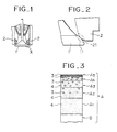
- Fig. 1 shows the exhaust valve according to the invention for Diesel engine, and the exhaust valve is composed of the valve body 1 and the valve seat 2.
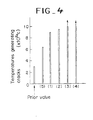
- Fig. 2 enlarges X portion in Fig. 1, and mutual contacting portions of the valve body 1 and the valve seat 2 are seat faces 11, 21.
- the seat face is formed with the coated layer of metals and ceramics, and the ceramic density becomes higher as advancing toward its surface.
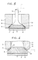
- Fig. 3 shows an example of such coated layers, in which reference A is the coated layer, and B is the mother material of the valve body 1 or the valve seat 2.
- the coated layer has multi layer structure and changes the ceramic density per each of the layers.
- the coated layer A is composed of A1 to A5 layers being different in the ceramic density.
- the layer A5 as the uppermost layer is almost ceramics only, and the layer A1 as the lowest layer is almost metals only.
- the middle layers A2 to A4 are complex of ceramics and metals, and the ceramic density is thicker as going toward the surface, that is, in the order of A2, A3, A4.
- the coated layer of multi layered structure is optional in 2 layer structure or 3 layer structure. If the layer were double, the upper would be ceramics or complex of ceramics and metals and the lower would be metals. If the layer were triple, the upper would be ceramics, the middle would be ceramics-metals and the lower would be metals, otherwise the upper and the middle layers would be complex of ceramics and metals, and the lower would be metals. With this structure of the coated layer, the seat surface may be given high corrosion resistibility and toughness.
- the middle layer shown in Fig. 3 is a complex of ceramics 3 and metals 4, and this complex layer has significance as follows.
- the hard layer as ceramics is thicker, but in view of assuring shock resistibility (toughness) and exfoliation resistibility, it is preferable that the ceramic layer is thinner.
- the complex layer satisfies to a certain extent both requirements opposite each other.
- the surface layer is composed with ceramics only as seen in Fig. 3.
- ceramics especially oxide ceramics (e.g., Zr0 2 ) or nitride ceramics (e.g., BN, SiN) there are such ceramics which could not be enough expected about toughness if not combining metals. Accordingly, in this case, the surface layer is preferable in the ceramic-metal complex layer.
- the ceramic-metal complex layer may be made with ceramic grains covered with metals.
- One coated layer can be formed by appropriately using the metal covered ceramic grains, ordinary ceramin grains and metal grains.
- One example of using such metal covered ceramic grains is the structure of the ceramic surface layer, the ceramic-metal complex middle layer of the metal covered ceramic grains and the metallic lowest layer.
- the metal covered ceramic grains may be used for forming the surface layer of the coated layer.
- alloys are main as NiCrAI, NiCrCo and NiCrMo. It is preferable to use several kinds of metals having different characteristics of corrosion resistibility and strength with respect to the coated layer. That is, the surface layer is formed with metals excellent in corrosion resistibility (e.g., NiCrAI) and the lowest layer is formed with metals excellent in strength (e.g., NiCrMo) and the middle layer is composed with metals having properly corrosion resistibility and strength (e.g., NiCrCo).
- thickness of coated layer If the surface is composed with ceramics only, thickness thereof will be preferable in range between 30 and 500 microns in order to satisfy corrosion resistibility and thermal shock resistibility. In order to exactly avoid penetration of molten oxides into the mother material, at least 70 microns will be required for thickness.
- the upper limit of 500 microns is a limit value where cracks are not generated even if the surface layer is heated and soaked at 800°C and water cooled (in a case of 100 microns in thickness of the lower metal layer), and it is actually preferable that the limit is 100 microns.
- Thickness of the lower metal layer depends upon coarseness of the base (mother material), and it is assumed to require at leust 100 microns for absorbing thermal shock or shocks when opening and closing the valve, and less than 1000 microns are suitable in economical viewpoint.
- Overall thickness of the coated layer will be around 130 to 6000 microns, and practically 350 to 2000 microns. If the double structure has the upper layer of ceramics and the lower layer of metals, the most suitable thickness will be 250 to 400 microns.
- the seat surface is composed with the coated layer by subjecting it to a pressing-heating treatment.
- This structure of the seat surface is the same as having mentioned. Passing through this treatment, the structure of the coated layer is made closer and is given larger toughness, corrosion resistibility and anti-invasion to the seat surface.
- the pressing-heating treatment will be referred to in detail.
- the present embodiment used the materials as above said to compose the coated layer of a plurality of layers being different in the ceramic density so that the ceramic density was stepwise changed.
- the coated layer of 3000 microns in thickness was composed of 5 layers in total, and from the surface the layer of 0 to 30 microns was the 100% ceramic layer, the layer of 2000 to 3000 microns was the 100% metal layer, and the middle three layers were the ceramic-metal complex layer where the ceramic density was higher at the upper part.
- the exhaust valve (5) having the seat surface of ceramics only caused the exfoliation on the surface in 150hr in the actual work, and the overall ceramic layer was exfoliated in 1400hr.
- exfoliations were found as follows, the valve (1): 2500 to 3500hr, the valve (2): 3500 to 5000hr, the valve (3): 5000 to 7000hr, and the valve (4): 7000 to 10000hr.
- the vickers hardness was tested to measure the loading value creating cracks in the seat surface. Cracks were created at pressure of 300 to 500g.
- the valve (1) was cracked at pressure of 300 to 500g, but the others were cracked as follows, the valve (2): more than 1 Kg, the valve (3): more than 1 to 5Kg, the valve (4): more than 10 to 30Kg.
- Fig. 5 shows thermal shock resistibility (temperatures when immersing into the water after heating and generating cracks) of the valves (1) to (4) and the conventional one (weld padding on the seat surface).
- the valve (5) shows satisfactory thermal shock resistibility in comparison with the conventional one, it could not fully absorb thermal shock due to difference in thermal expansion between the ceramics layer and the mother material, and so cracks were created at the heating temperature of 650°C.
- the inventive valves (1) to (4) all showed the satisfactory thermal shock resistibility over the exhaust valve (5).
- the exhaust valve of the invention is formed with the seat surface by coating ceramics and metals such that the ceramic density becomes thicker as advancing toward the said face, and may provide characteristics as follows. That is, due to ceramics more contained at the upper part, the seat is made excellent in hardness at the high temperatures and corrosion resistibility, and the corrosion amount at the high temperatures may be reduced 1/2 to 1/10 of the conventional exhaust valve (weld padding on the seat). Said ceramics avoids penetration of oxides of low melting point such as V 2 0 s , Na 2 SO 4 and others into the interior of the seat and avoids occurrence of accelerated oxidation at high temperatures, thereby exactly avoiding blowing-burning due to this accelerated oxidation.
- oxides of low melting point such as V 2 0 s , Na 2 SO 4 and others
- the fabrication of the coated layer, especially of the ceramic layer is made ⁇ Iose, thereby to obtain higher corrosion resistibility and toughness, and besides by making close the whole fabrication the adhering property with the mother material can be more imparted, and thus the blowing-burning, exfoliation and others can be exactly avoided.
- the mother material (valve body and seat) is under-cut on a portion to be formed with the seat in accordance with thickness of a coating layer, and subsequently this portion is blasted with white alumina, and removal of blast powder and degrease are undertaken. Coating is carried out after this process. Ceramic grains, metal covered ceramic grains and metal grains are coated at determined ratio on the portion to be a seat such that the ceramic density becomes higher as going to the surface. For making the coated layer as shown in Fig. 3, the coating is performed by stepwise coating a plurality of materials being different in the mixing ratio of said grains.
- the process may depend upon the plasma, the thermospray or other suitable ways.
- coatings it is possible to properly use metals of several kinds being different in the characteristics (anti-corrosion, toughness, etc.) in coating height of the coated layer.
- the exhaust valve according to the invention has practical durability, though the seat surface is as-coated. Durability is more increased by undertaking the pressing-heating treatment on the coated layer. This treatment is done by heating the coated layer in the non-oxidizing atmosphere while pressing it.
- Fig. 3 the layers different in the mixing ratio of the grains, are formed in succession from the lowest side, and the finished layers are subjected to the pressing-heating treatment, in other words, coatings and treatings are repeated several times to form the coated layer.
- Figs. 5 and 6 show the pressing-heating conditions.
- Fig. 5 is concerned with the valve body.
- the valve body 1 is inserted into a tool 5 at its corresponding part, and the coated layer A is contacted to an inner circumference 51 of taper.
- a tool 6 is urged to a lower surface of the valve body 1 via an insulator 7, and the coated layer A is pressed to the inner circumference 51 of the tool 5 at determined static load. Under this condition electric conductivity is made between a valve bar 12 and the tool 5 to heat the coated layer A.
- Fig. 6 is concerned with the valve seat.
- the coated layer A is contacted to an outer circumference 81 of taper of a tool 8.
- a tool 9 is urged to a lower surface of the tool 8 via an insulator 10, and the coated layer A is pressed to the outer circumference 81 of the tool 8 at determined static load. Under this condition, electric conductivity is made between the valve seat 2 and the tool 8 to heat the coated layer A.
- the pressing-heating tool is made of, e.g., Nimonic alloy and has coating of solid lubricant (e.g., graphite lubricant) on the contacting face with the coated layer A.
- solid lubricant e.g., graphite lubricant
- the coated layer A should be heated in temperature range below the melting point of the substances forming the coated layer.
- the heating temperature is around 900°C to the maximum and in general 700 to 800°C.
- Conductivity of 200V and 30Kw is required for the heating.
- Static load for conductive heating should be to the extent that creep deformation of the mother material can be ignored, and therefore limit is 10Kg/mm 2 and generally 3 to 7Kg/mm z .
- inert gas is, e.g., Ar gas where the treatment is undertaken.
Landscapes
- Engineering & Computer Science (AREA)
- Mechanical Engineering (AREA)
- General Engineering & Computer Science (AREA)
- Chemical & Material Sciences (AREA)
- Ceramic Engineering (AREA)
- Combustion & Propulsion (AREA)
- Other Surface Treatments For Metallic Materials (AREA)
- Coating By Spraying Or Casting (AREA)
Description
- The invention relates to a method for making an exhaust valve for a Diesel engine according to the preamble of the claim.
- An exhaust valve to be used in a Diesel engine is easily burnt by exhausted gas, and this is remarkable in middle or high speed Diesel engine issuing the gas of high temperatures, especially in a case of using inferior or bad oil. Such problem involved with burning is in general found in blowing at a valve body and a valve seat composing the exhaust valve. The exhausted gas of Diesel engine much contains, in relation with the fuel, oxides of low melting point as
V 205 or Na2SO4, and these oxides penetrate into the seat and cause oxidization accelerated at high temperatures so that said blowing and burning occur. The prior art has employed Cr-heat resisting steel or Ni-based super heat resisting alloy for the mother material of the valve body and the valve seat in order to provide countermeasures to avoid said phenomena. A portion to compose the seat of the mother material is prepared with weld padding or coat padding of corrosion resistable alloy of Co based or Ni based high hardness (Hv 600 to 700). However when the fuel is inferior, the seat would be instantly hurt by blowing and burning, since it is only padded with the corrosion resistible alloy. On the other hand, there has been an attempt for coating on the mother material a substance where ceramics is dispersed in Co based or Ni based alloy, but such coated layer of metals and ceramics uniformly dispersed is poor in durability against repeated shocks. In addition, the coated layer dispersed with ceramics is low in density, and the compound of low melting point which accelerates oxidization at the high temperatures penetrates into the coated layer and further to the mother material, so that the blowing-burning is invited in turn. It may be also assumed to form the seat with ceramic layer for assuring corrosion resistibility,. but since such seat is poor in thermal shock resistibility and toughness, cracks or exfoliation are easily effected and its practicability is very difficult. - CH-A-291 607 describes a heatproof and heat-insulating material for embodying or covering parts of an internal combustion engine, said material consisting of a mixture of quartz and metal particles. There are provided quartz plates, discs and the like, at the bottom of which metal particles are incorporated in the quartz material in such a way that the maximum concentration of the metal particles at the bottom of the plate or the like is gradually diminished from the lower to the upper side, so that the upper side of the plate only consists of quartz. A valve embodied according to the disclosure of CH-A-291 607 does not meet the requirements for an exhaust valve to be used with Diesel engine especially as to delamination under heat shocks.
- DE-A-2 856 232 discloses a valve for a combustion engine, which is all over covered by a ceramic layer for protection against corrosion, especially at high temperatures. The ceramic layer is bonded to the valve body via a metal layer, which is improving the adhesion of the outer ceramic layer.
- Further from DE-A-2 456 435 a pressure- heating treatment of elements for an engine or the like is known, which consists in a first portion of ceramics and in a second portion of a weldable material like metal. Such a structure is provided for connecting an element consisting of ceramics with another element consisting of metal.
- It is the object of the invention to provide a method for making an exhaust valve according to the preamble of the claim, which valve is imparted with excellent corrosion resistability, thermal shock resistability, toughness and adhesion with the mother material.
- This is achieved by the features in the characterizing part of the claim. By this method corrosion resistability as well as resistability to thermal shocks and toughness as well as adhesion can be much improved.
- The invention is explained in detail by way of an example in connection with the drawings.
- Fig. 1 is a vertically cross sectional view showing the exhaust valve according to the invention,
- Fig. 2 is a partially enlarged view of X portion in Fig. 1,
- Fig. 3 is a cross sectional view of an exhaust valve according to the invention,
- Fig. 4 is a graph showing comparison of thermal shock resistibility of the exhaust valve in Example 2 with an ordinary exhaust valve,
- Fig. 5 is an explanatory view showing the pressing-heating treatment subjecting to the coated layer of the seat of the valve body, and
- Fig. 6 is an explanatory view showing the pressing-heating treatment subjecting to the coated layer of the seat of the valve seat.
- Embodiments of the invention will be explained in reference to the attached drawings. Fig. 1 shows the exhaust valve according to the invention for Diesel engine, and the exhaust valve is composed of the
valve body 1 and thevalve seat 2. Fig. 2 enlarges X portion in Fig. 1, and mutual contacting portions of thevalve body 1 and thevalve seat 2 areseat faces 11, 21. The seat face is formed with the coated layer of metals and ceramics, and the ceramic density becomes higher as advancing toward its surface. Fig. 3 shows an example of such coated layers, in which reference A is the coated layer, and B is the mother material of thevalve body 1 or thevalve seat 2. The coated layer has multi layer structure and changes the ceramic density per each of the layers. The coated layer A is composed of A1 to A5 layers being different in the ceramic density. The layer A5 as the uppermost layer is almost ceramics only, and the layer A1 as the lowest layer is almost metals only. The middle layers A2 to A4 are complex of ceramics and metals, and the ceramic density is thicker as going toward the surface, that is, in the order of A2, A3, A4. The coated layer of multi layered structure is optional in 2 layer structure or 3 layer structure. If the layer were double, the upper would be ceramics or complex of ceramics and metals and the lower would be metals. If the layer were triple, the upper would be ceramics, the middle would be ceramics-metals and the lower would be metals, otherwise the upper and the middle layers would be complex of ceramics and metals, and the lower would be metals. With this structure of the coated layer, the seat surface may be given high corrosion resistibility and toughness. - The middle layer shown in Fig. 3 is a complex of
ceramics 3 andmetals 4, and this complex layer has significance as follows. In view of assuring anti-invasion of foreign substances into the seat, it is preferable that the hard layer as ceramics is thicker, but in view of assuring shock resistibility (toughness) and exfoliation resistibility, it is preferable that the ceramic layer is thinner. The complex layer satisfies to a certain extent both requirements opposite each other. By preparing the ceramic-metal complex layer having properly hardness and toughness in the middle layer, shock proof of ceramics may be provided in the surface layer while anti-invasion may be increased. Therefore, a preferred embodiment of the invention is that if the uppermost layer is composed with ceramics only, the middle layer is formed with the ceramic-metal complex layer. - In viewpoint of maintaining anti-corrosion and anti-invasion, it is desirable that the surface layer is composed with ceramics only as seen in Fig. 3. However, among ceramics, especially oxide ceramics (e.g., Zr02) or nitride ceramics (e.g., BN, SiN) there are such ceramics which could not be enough expected about toughness if not combining metals. Accordingly, in this case, the surface layer is preferable in the ceramic-metal complex layer.
- The ceramic-metal complex layer may be made with ceramic grains covered with metals. One coated layer can be formed by appropriately using the metal covered ceramic grains, ordinary ceramin grains and metal grains. One example of using such metal covered ceramic grains is the structure of the ceramic surface layer, the ceramic-metal complex middle layer of the metal covered ceramic grains and the metallic lowest layer. The metal covered ceramic grains may be used for forming the surface layer of the coated layer.
- For ceramics to be used as mentioned above, limitation is not specially made to, but various kinds could be employed in oxides, carbides, nitrides and others. Representatives will be
AI 203, Ti02 and Zr02. For the metals, alloys are main as NiCrAI, NiCrCo and NiCrMo. It is preferable to use several kinds of metals having different characteristics of corrosion resistibility and strength with respect to the coated layer. That is, the surface layer is formed with metals excellent in corrosion resistibility (e.g., NiCrAI) and the lowest layer is formed with metals excellent in strength (e.g., NiCrMo) and the middle layer is composed with metals having properly corrosion resistibility and strength (e.g., NiCrCo). - A next reference will be made to thickness of coated layer. If the surface is composed with ceramics only, thickness thereof will be preferable in range between 30 and 500 microns in order to satisfy corrosion resistibility and thermal shock resistibility. In order to exactly avoid penetration of molten oxides into the mother material, at least 70 microns will be required for thickness. The upper limit of 500 microns is a limit value where cracks are not generated even if the surface layer is heated and soaked at 800°C and water cooled (in a case of 100 microns in thickness of the lower metal layer), and it is actually preferable that the limit is 100 microns.
- Thickness of the lower metal layer depends upon coarseness of the base (mother material), and it is assumed to require at leust 100 microns for absorbing thermal shock or shocks when opening and closing the valve, and less than 1000 microns are suitable in economical viewpoint.
- Overall thickness of the coated layer will be around 130 to 6000 microns, and practically 350 to 2000 microns. If the double structure has the upper layer of ceramics and the lower layer of metals, the most suitable thickness will be 250 to 400 microns.
- In the invention, the seat surface is composed with the coated layer by subjecting it to a pressing-heating treatment. This structure of the seat surface is the same as having mentioned. Passing through this treatment, the structure of the coated layer is made closer and is given larger toughness, corrosion resistibility and anti-invasion to the seat surface.
- The pressing-heating treatment will be referred to in detail.
- Actual embodiments will be shown.

- The present embodiment used the materials as above said to compose the coated layer of a plurality of layers being different in the ceramic density so that the ceramic density was stepwise changed. The coated layer of 3000 microns in thickness was composed of 5 layers in total, and from the surface the layer of 0 to 30 microns was the 100% ceramic layer, the layer of 2000 to 3000 microns was the 100% metal layer, and the middle three layers were the ceramic-metal complex layer where the ceramic density was higher at the upper part.
- Investigations were made to the exhaust valves of the invention of several embodiments as shown in following table and the comparative one of the coated layer having ceramics only with respect to the characteristics thereof. In them, (1) to (4) were the inventive exhaust valves, and (5) was the comparative valve. In the exhaust valve (1), the upper was ceramics and the lower was metals. In the valve (2), the upper was the ceramic-metal complex layer and the lower was metals. In the valve (3), the upper was the complex layer of the metal covered ceramic grains and the lower was metals, and in this complex layer the covering metal was 0 to 75wt% of the total grains. The valve (4) was made by performing the pressing-heating treatment on the coated layer of the valve (3). The comparative valve (5) was formed with the ceramic coated layer on the ground treatment.

- The exhaust valve (5) having the seat surface of ceramics only caused the exfoliation on the surface in 150hr in the actual work, and the overall ceramic layer was exfoliated in 1400hr. On the other hand, in the invention, exfoliations were found as follows, the valve (1): 2500 to 3500hr, the valve (2): 3500 to 5000hr, the valve (3): 5000 to 7000hr, and the valve (4): 7000 to 10000hr. Further, in order to appreciate the anti-invasion into the seat surface, the vickers hardness was tested to measure the loading value creating cracks in the seat surface. Cracks were created at pressure of 300 to 500g. On the other hand, the valve (1) was cracked at pressure of 300 to 500g, but the others were cracked as follows, the valve (2): more than 1 Kg, the valve (3): more than 1 to 5Kg, the valve (4): more than 10 to 30Kg. Fig. 5 shows thermal shock resistibility (temperatures when immersing into the water after heating and generating cracks) of the valves (1) to (4) and the conventional one (weld padding on the seat surface). In this figure, although the valve (5) shows satisfactory thermal shock resistibility in comparison with the conventional one, it could not fully absorb thermal shock due to difference in thermal expansion between the ceramics layer and the mother material, and so cracks were created at the heating temperature of 650°C. On the other hand, the inventive valves (1) to (4) all showed the satisfactory thermal shock resistibility over the exhaust valve (5).
- As having discussed, the exhaust valve of the invention is formed with the seat surface by coating ceramics and metals such that the ceramic density becomes thicker as advancing toward the said face, and may provide characteristics as follows. That is, due to ceramics more contained at the upper part, the seat is made excellent in hardness at the high temperatures and corrosion resistibility, and the corrosion amount at the high temperatures may be reduced 1/2 to 1/10 of the conventional exhaust valve (weld padding on the seat). Said ceramics avoids penetration of oxides of low melting point such as
V 20s, Na2SO4 and others into the interior of the seat and avoids occurrence of accelerated oxidation at high temperatures, thereby exactly avoiding blowing-burning due to this accelerated oxidation. Since ceramics brings about reaction with said low melting oxides as high as around 900°C, the high temperature corrosion due to the low melting oxides scarcely takes place in the range of 600 to 700°C where the seat of the exhaust valve serves. In addition to these characteristics, metals contained much in the lower part make the seat surface tough and excellent in adhesion with the mother material. This characteristic property is remarkable when the ceramic-metal complex layer is prepared for the surface layer and the middle layer. Furthermore, under mentioned characteristic properties may be obtained by the surface ceramics. High hardness is imparted on the seat surface by the surface ceramics, so that the blowing loss on the seat by invasion of hard substances can be prevented. Ceramics on the surface layer keep off adhesion of harmful substances as burnt remainders to the seat surface, and further due to the heat insulating effect of ceramics, temperature around the seat surface may be considerably lowered in corporation with water cooling. - In the present exhaust valve the fabrication of the coated layer, especially of the ceramic layer is made εIose, thereby to obtain higher corrosion resistibility and toughness, and besides by making close the whole fabrication the adhering property with the mother material can be more imparted, and thus the blowing-burning, exfoliation and others can be exactly avoided.
- A further reference will be made to a method of making the exhaust valves.
- An example of a prior process to coating will be briefly referred to. The mother material (valve body and seat) is under-cut on a portion to be formed with the seat in accordance with thickness of a coating layer, and subsequently this portion is blasted with white alumina, and removal of blast powder and degrease are undertaken. Coating is carried out after this process. Ceramic grains, metal covered ceramic grains and metal grains are coated at determined ratio on the portion to be a seat such that the ceramic density becomes higher as going to the surface. For making the coated layer as shown in Fig. 3, the coating is performed by stepwise coating a plurality of materials being different in the mixing ratio of said grains.
- The process may depend upon the plasma, the thermospray or other suitable ways. In said coatings, it is possible to properly use metals of several kinds being different in the characteristics (anti-corrosion, toughness, etc.) in coating height of the coated layer.
- The exhaust valve according to the invention has practical durability, though the seat surface is as-coated. Durability is more increased by undertaking the pressing-heating treatment on the coated layer. This treatment is done by heating the coated layer in the non-oxidizing atmosphere while pressing it.
- In Fig. 3 the layers different in the mixing ratio of the grains, are formed in succession from the lowest side, and the finished layers are subjected to the pressing-heating treatment, in other words, coatings and treatings are repeated several times to form the coated layer.
- Figs. 5 and 6 show the pressing-heating conditions. Fig. 5 is concerned with the valve body. The
valve body 1 is inserted into atool 5 at its corresponding part, and the coated layer A is contacted to aninner circumference 51 of taper. A tool 6 is urged to a lower surface of thevalve body 1 via an insulator 7, and the coated layer A is pressed to theinner circumference 51 of thetool 5 at determined static load. Under this condition electric conductivity is made between avalve bar 12 and thetool 5 to heat the coated layer A. - Fig. 6 is concerned with the valve seat. The coated layer A is contacted to an
outer circumference 81 of taper of a tool 8. A tool 9 is urged to a lower surface of the tool 8 via aninsulator 10, and the coated layer A is pressed to theouter circumference 81 of the tool 8 at determined static load. Under this condition, electric conductivity is made between thevalve seat 2 and the tool 8 to heat the coated layer A. - The pressing-heating tool is made of, e.g., Nimonic alloy and has coating of solid lubricant (e.g., graphite lubricant) on the contacting face with the coated layer A.
- The coated layer A should be heated in temperature range below the melting point of the substances forming the coated layer. The heating temperature is around 900°C to the maximum and in general 700 to 800°C. Conductivity of 200V and 30Kw is required for the heating. Static load for conductive heating should be to the extent that creep deformation of the mother material can be ignored, and therefore limit is 10Kg/mm2 and generally 3 to 7Kg/mmz. For the non-oxidizing atmosphere, inert gas is, e.g., Ar gas where the treatment is undertaken.
Claims (1)
- Method for making an exhaust valve for a diesel engine consisting of a mother material and comprisinga corrosion resistable coating layer consisting of ceramics and metal, the density of ceramics increasing from the inside of the layer to its upper surface, whereby said coating layer is composed of at least two layers one of which is a layer of ceramic and metal complex, characterized by the fact:that the coating layer is composed on the surface part of a ceramic layer, on the middle part of a ceramic and metal complex layer and on the lower part of a metal layer or said coating layer is composed on the surface part of a ceramic and metal complex layer and on the lower part of a metal layer and that the mother material of the valve seating portion is coated with said layers in such way that coating is carried out separately for each of said layers, and so that after each coating the last coated layer is heated by means of electric conductivity, while the layer is pressed by means of a tool in a non-oxidizing atmosphere.
Applications Claiming Priority (4)
| Application Number | Priority Date | Filing Date | Title |
|---|---|---|---|
| JP152264/80 | 1980-10-31 | ||
| JP15226480A JPS5776214A (en) | 1980-10-31 | 1980-10-31 | Exhaust valve of diesel engine and manufacture therefor |
| JP14962081A JPS5852469A (en) | 1981-09-24 | 1981-09-24 | Exhaust valve for diesel engine |
| JP149620/81 | 1981-09-24 |
Publications (2)
| Publication Number | Publication Date |
|---|---|
| EP0051300A1 EP0051300A1 (en) | 1982-05-12 |
| EP0051300B1 true EP0051300B1 (en) | 1986-09-10 |
Family
ID=26479451
Family Applications (1)
| Application Number | Title | Priority Date | Filing Date |
|---|---|---|---|
| EP81109361A Expired EP0051300B1 (en) | 1980-10-31 | 1981-10-30 | Method for making an exhaust valve for a diesel engine |
Country Status (3)
| Country | Link |
|---|---|
| US (4) | US4530322A (en) |
| EP (1) | EP0051300B1 (en) |
| DE (1) | DE3175312D1 (en) |
Families Citing this family (42)
| Publication number | Priority date | Publication date | Assignee | Title |
|---|---|---|---|---|
| JPS60188805U (en) * | 1984-05-28 | 1985-12-14 | 本田技研工業株式会社 | Cylinder head for internal combustion engine |
| DE3447784C2 (en) * | 1984-12-20 | 1987-03-12 | Gebrüder Sulzer AG, Winterthur | Piston internal combustion engine |
| JPS61275512A (en) * | 1985-05-30 | 1986-12-05 | Nippon Kokan Kk <Nkk> | Engine component and manufacture thereof |
| JPS6213820A (en) * | 1985-07-12 | 1987-01-22 | Ngk Insulators Ltd | Ceramic sliding member |
| JPS62107216A (en) * | 1985-11-05 | 1987-05-18 | Ngk Insulators Ltd | Valve seat insert and cylinder head comprising same |
| US4688527A (en) * | 1986-03-31 | 1987-08-25 | Chrysler Motors Corporation | Ceramic valve guide and seat |
| JPS6341608A (en) * | 1986-08-08 | 1988-02-22 | Ngk Insulators Ltd | Ceramic valve seat |
| JPS63171622U (en) * | 1987-04-28 | 1988-11-08 | ||
| GB2238349B (en) * | 1989-11-25 | 1993-09-15 | T & N Technology Ltd | Ceramic coated engine valves. |
| US5094200A (en) * | 1991-05-28 | 1992-03-10 | Ford Motor Company | Lightweight composite engine valve |
| US5240741A (en) * | 1991-12-20 | 1993-08-31 | United Technologies Corporation | Inhibiting coke formation by coating gas turbine elements with tungsten disulfide |
| US5336560A (en) * | 1991-12-20 | 1994-08-09 | United Technologies Corporation | Gas turbine elements bearing alumina-silica coating to inhibit coking |
| US5266360A (en) * | 1991-12-20 | 1993-11-30 | United Technologies Corporation | Inhibiting coke formation by coating gas turbine elements with silica |
| US5324544A (en) * | 1991-12-20 | 1994-06-28 | United Technologies Corporation | Inhibiting coke formation by coating gas turbine elements with alumina-silica sol gel |
| US5295461A (en) * | 1992-04-13 | 1994-03-22 | Ford Motor Company | Oil-starved valve assembly |
| US5503122A (en) * | 1992-09-17 | 1996-04-02 | Golden Technologies Company | Engine components including ceramic-metal composites |
| DE69312679T2 (en) * | 1993-03-26 | 1998-02-19 | Fuji Valve | Compensation element structure for a valve lifter of an internal combustion engine |
| JP3287916B2 (en) * | 1993-07-20 | 2002-06-04 | ヤマハ発動機株式会社 | Joint structure of valve seat |
| DE4328732C1 (en) * | 1993-08-26 | 1995-02-16 | Castolin Sa | Process for producing a thermally sprayed metal-containing layer and a material for this purpose |
| AU2379895A (en) * | 1994-03-31 | 1995-10-23 | Golden Technologies Company, Inc. | Engine components including ceramic-metal composites |
| US5899185A (en) * | 1994-11-25 | 1999-05-04 | Fuji Oozx Inc. | Method of increasing heat transfer of a fitted material of a cylinder head in an internal combustion engine and a fitted portion of the fitted material |
| US5778531A (en) * | 1995-09-14 | 1998-07-14 | Yamaha Hatsudoki Kabushiki Kaisha | Method of manufacturing cylinder head for engine |
| JPH0979012A (en) * | 1995-09-14 | 1997-03-25 | Yamaha Motor Co Ltd | Manufacturing method of engine cylinder head |
| JPH0979014A (en) * | 1995-09-14 | 1997-03-25 | Yamaha Motor Co Ltd | Manufacturing method of engine cylinder head |
| JP3011076B2 (en) * | 1995-10-31 | 2000-02-21 | トヨタ自動車株式会社 | Cylinder head of internal combustion engine |
| DK173348B1 (en) | 1996-06-07 | 2000-08-07 | Man B & W Diesel As | Exhaust valve for an internal combustion engine |
| US6009843A (en) * | 1997-10-22 | 2000-01-04 | 3M Innovative Properties Company | Fiber reinforced, titanium composite engine valve |
| DE19960884C2 (en) | 1999-12-17 | 2003-10-30 | Daimler Chrysler Ag | Coating method for thermally and mechanically loaded areas of internal combustion engines |
| US6908639B2 (en) * | 2001-04-02 | 2005-06-21 | Micron Technology, Inc. | Mixed composition interface layer and method of forming |
| GB0121429D0 (en) * | 2001-09-05 | 2001-10-24 | Trw Ltd | A friction member and method of production of same |
| JP2003307105A (en) * | 2002-04-12 | 2003-10-31 | Fuji Oozx Inc | Engine valve |
| DE10255447A1 (en) * | 2002-11-28 | 2004-06-24 | Daimlerchrysler Ag | Valve seat and method for producing a valve seat |
| DE102004060538B3 (en) * | 2004-12-16 | 2006-03-16 | Daimlerchrysler Ag | Firmly adhered hard metal layers on substrates, especially valve seating rings on cylinder heads, produced using adhesion-promoting layer formed by applying plasma jet containing hard metal to substrate |
| US7562647B2 (en) * | 2006-03-29 | 2009-07-21 | High Performance Coatings, Inc. | Inlet valve having high temperature coating and internal combustion engines incorporating same |
| US20080032065A1 (en) * | 2006-03-30 | 2008-02-07 | High Performance Coatings, Inc. | Methods for coating engine valves with protective coatings using infrared radiation |
| US7559991B2 (en) | 2006-03-30 | 2009-07-14 | High Performance Coatings, Inc. | Apparatus for coating engine valves with protective coatings and curing the coatings using infrared radiation |
| DE102007031464A1 (en) * | 2006-07-17 | 2008-01-24 | Alstom Technology Ltd. | Steam inlet valve of a steam turbine |
| DK177071B1 (en) * | 2009-10-30 | 2011-05-30 | Man Diesel & Turbo Deutschland | Exhaust valve spindle for an internal combustion engine and a method of manufacture thereof |
| CN109058484B (en) | 2013-11-26 | 2021-10-15 | S.P.M.流量控制股份有限公司 | Valve seats used in fracturing pumps |
| DK177960B1 (en) * | 2014-04-08 | 2015-02-02 | Man Diesel & Turbo Deutschland | An exhaust valve for an internal combustion engine |
| CN110425050A (en) * | 2019-07-26 | 2019-11-08 | 中国第一汽车股份有限公司 | A kind of cylinder head assembly moulding process and cylinder head |
| CN119768233A (en) * | 2022-08-22 | 2025-04-04 | 康明斯有限公司 | Multi-composition thermal management coating system for combustion chamber components |
Citations (2)
| Publication number | Priority date | Publication date | Assignee | Title |
|---|---|---|---|---|
| GB665330A (en) * | 1949-08-16 | 1952-01-23 | Alliance Europ | Improvements in or relating to the combustion chambers and pistons of internal combustion engines |
| GB2015397A (en) * | 1978-03-04 | 1979-09-12 | Maschf Augsburg Nuernberg Ag | Coating poppet valves |
Family Cites Families (22)
| Publication number | Priority date | Publication date | Assignee | Title |
|---|---|---|---|---|
| CA767594A (en) * | 1967-09-19 | O. S. Stark Sven | Bonding of ceramic material to metal by flame spraying | |
| US1559439A (en) * | 1925-01-16 | 1925-10-27 | Edward W Kapraun | Internal-combustion engine |
| US2273250A (en) * | 1938-03-24 | 1942-02-17 | Eaton Mfg Co | Method of making valve parts or the like |
| CH291607A (en) * | 1948-08-16 | 1953-06-30 | Alliance Europ | Internal combustion engine. |
| BE588969A (en) * | 1959-03-26 | |||
| US3082752A (en) * | 1961-04-04 | 1963-03-26 | Reynolds Metals Co | Lined engine members and methods of making the same or the like |
| CH465323A (en) * | 1964-07-08 | 1968-11-15 | Bluecher Wahlstatt Leichtmet | Process for armoring valve cones for internal combustion engines |
| US3649380A (en) * | 1969-04-14 | 1972-03-14 | Trw Inc | Method of manufacturing hard faced exhaust valves |
| JPS5346768B2 (en) * | 1973-01-11 | 1978-12-16 | ||
| US3975165A (en) * | 1973-12-26 | 1976-08-17 | Union Carbide Corporation | Graded metal-to-ceramic structure for high temperature abradable seal applications and a method of producing said |
| JPS50101205A (en) * | 1974-01-12 | 1975-08-11 | ||
| DE2433896A1 (en) * | 1974-07-15 | 1976-02-05 | Volkswagenwerk Ag | Otto engine exhaust valve seat reinforcement - applies blunt conical blank to seat by friction welding |
| US4074671A (en) * | 1974-10-31 | 1978-02-21 | Pennila Simo A O | Thin and low specific heat ceramic coating and method for increasing operating efficiency of internal combustion engines |
| DE2456435C2 (en) * | 1974-11-29 | 1983-12-29 | Volkswagenwerk Ag, 3180 Wolfsburg | Method for producing a one-piece workpiece which consists of a non-oxidic ceramic material in a first area and in which a second area is suitable for forming a soldered or welded connection with a metal part |
| CH602237A5 (en) * | 1974-12-23 | 1978-07-31 | Bbc Brown Boveri & Cie | |
| US4248940A (en) * | 1977-06-30 | 1981-02-03 | United Technologies Corporation | Thermal barrier coating for nickel and cobalt base super alloys |
| US3990860A (en) * | 1975-11-20 | 1976-11-09 | Nasa | High temperature oxidation resistant cermet compositions |
| US4109031A (en) * | 1976-12-27 | 1978-08-22 | United Technologies Corporation | Stress relief of metal-ceramic gas turbine seals |
| US4376374A (en) * | 1977-11-16 | 1983-03-15 | Repwell Associates, Inc. | Metal-ceramic composite and method for making same |
| DE2856232A1 (en) * | 1978-12-27 | 1980-07-17 | Teves Thompson Gmbh | Mushroom valve for exhaust gas turbocharger - has hard metal seat on base covered with corrosion and temp.-resistant layer |
| US4269903A (en) * | 1979-09-06 | 1981-05-26 | General Motors Corporation | Abradable ceramic seal and method of making same |
| DE3137731A1 (en) * | 1981-09-23 | 1983-04-14 | Battelle-Institut E.V., 6000 Frankfurt | HIGH TEMPERATURE AND THERMAL SHOCK RESISTANT COMPACT MATERIALS AND COATINGS |
-
1981
- 1981-10-28 US US06/315,666 patent/US4530322A/en not_active Expired - Fee Related
- 1981-10-30 EP EP81109361A patent/EP0051300B1/en not_active Expired
- 1981-10-30 DE DE8181109361T patent/DE3175312D1/en not_active Expired
-
1985
- 1985-02-25 US US06/705,216 patent/US4554897A/en not_active Expired - Fee Related
- 1985-02-25 US US06/705,324 patent/US4556022A/en not_active Expired - Fee Related
-
1986
- 1986-03-13 US US06/839,088 patent/US4661371A/en not_active Expired - Fee Related
Patent Citations (2)
| Publication number | Priority date | Publication date | Assignee | Title |
|---|---|---|---|---|
| GB665330A (en) * | 1949-08-16 | 1952-01-23 | Alliance Europ | Improvements in or relating to the combustion chambers and pistons of internal combustion engines |
| GB2015397A (en) * | 1978-03-04 | 1979-09-12 | Maschf Augsburg Nuernberg Ag | Coating poppet valves |
Also Published As
| Publication number | Publication date |
|---|---|
| US4530322A (en) | 1985-07-23 |
| US4661371A (en) | 1987-04-28 |
| US4554897A (en) | 1985-11-26 |
| EP0051300A1 (en) | 1982-05-12 |
| US4556022A (en) | 1985-12-03 |
| DE3175312D1 (en) | 1986-10-16 |
Similar Documents
| Publication | Publication Date | Title |
|---|---|---|
| US4530322A (en) | Exhaust valve for diesel engine and production thereof | |
| US4554898A (en) | Exhaust valve for diesel engine and production thereof | |
| EP0075844B1 (en) | Heat resisting and insulating light alloy articles and method of manufacture | |
| US5040501A (en) | Valves and valve components | |
| US4787736A (en) | Laser clad valve for internal combustion engine | |
| EP0340791B1 (en) | Ceramics-coated heat resisting alloy member | |
| US6017591A (en) | Method of making adherently sprayed valve seats | |
| CN1081725C (en) | Movable wall member in form of exhaust valve spindle or piston is IC engine | |
| EP3915717A1 (en) | Ni-based alloy, and ni-based alloy product and methods for producing the same | |
| CN1692224A (en) | A nozzle for a fuel valve in a diesel engine, and a method of manufacturing a nozzle | |
| Arun et al. | Influence of silica on microstructural modification of electrical discharge composite coating and its wear performance | |
| JP3542702B2 (en) | Valve stem for diesel engine | |
| EP1132490B1 (en) | Piston with a metal matrix composite | |
| EP2318668B1 (en) | Cylinder head with valve seat and method for the production thereof | |
| US5803037A (en) | Joined type valve seat | |
| US7401586B2 (en) | Valve seat rings made of basic Co or Co/Mo alloys, and production thereof | |
| EP0605175B1 (en) | A coated article and a method of coating said article | |
| JPH09317413A (en) | Joining type valve seat | |
| EP0280480A2 (en) | Ceramic wall structures for engines and method of manufacture | |
| EP0204276B1 (en) | Components for engines and production therefor | |
| Moriyama et al. | Nimonic compound exhaust valve spindles for diesel engines via hot isostatic pressing | |
| RU2772481C1 (en) | Method for restoring the working valve face of the gas distribution mechanism of an internal combustion engine | |
| US10844757B2 (en) | Valve for internal-combustion engines | |
| EP3623591B1 (en) | Valve for internal-combustion engines | |
| JPH01177440A (en) | Cylinder head of aluminum alloy make |
Legal Events
| Date | Code | Title | Description |
|---|---|---|---|
| PUAI | Public reference made under article 153(3) epc to a published international application that has entered the european phase |
Free format text: ORIGINAL CODE: 0009012 |
|
| AK | Designated contracting states |
Designated state(s): CH DE FR GB SE |
|
| 17P | Request for examination filed |
Effective date: 19820623 |
|
| GRAA | (expected) grant |
Free format text: ORIGINAL CODE: 0009210 |
|
| AK | Designated contracting states |
Kind code of ref document: B1 Designated state(s): CH DE FR GB LI SE |
|
| REF | Corresponds to: |
Ref document number: 3175312 Country of ref document: DE Date of ref document: 19861016 |
|
| ET | Fr: translation filed | ||
| PLBE | No opposition filed within time limit |
Free format text: ORIGINAL CODE: 0009261 |
|
| STAA | Information on the status of an ep patent application or granted ep patent |
Free format text: STATUS: NO OPPOSITION FILED WITHIN TIME LIMIT |
|
| 26N | No opposition filed | ||
| PGFP | Annual fee paid to national office [announced via postgrant information from national office to epo] |
Ref country code: FR Payment date: 19941011 Year of fee payment: 14 |
|
| PGFP | Annual fee paid to national office [announced via postgrant information from national office to epo] |
Ref country code: SE Payment date: 19941017 Year of fee payment: 14 |
|
| PGFP | Annual fee paid to national office [announced via postgrant information from national office to epo] |
Ref country code: GB Payment date: 19941020 Year of fee payment: 14 |
|
| PGFP | Annual fee paid to national office [announced via postgrant information from national office to epo] |
Ref country code: DE Payment date: 19941021 Year of fee payment: 14 |
|
| PGFP | Annual fee paid to national office [announced via postgrant information from national office to epo] |
Ref country code: CH Payment date: 19941025 Year of fee payment: 14 |
|
| EAL | Se: european patent in force in sweden |
Ref document number: 81109361.6 |
|
| PG25 | Lapsed in a contracting state [announced via postgrant information from national office to epo] |
Ref country code: GB Effective date: 19951030 |
|
| PG25 | Lapsed in a contracting state [announced via postgrant information from national office to epo] |
Ref country code: SE Effective date: 19951031 Ref country code: LI Effective date: 19951031 Ref country code: CH Effective date: 19951031 |
|
| REG | Reference to a national code |
Ref country code: CH Ref legal event code: PL |
|
| GBPC | Gb: european patent ceased through non-payment of renewal fee |
Effective date: 19951030 |
|
| PG25 | Lapsed in a contracting state [announced via postgrant information from national office to epo] |
Ref country code: FR Effective date: 19960628 |
|
| EUG | Se: european patent has lapsed |
Ref document number: 81109361.6 |
|
| PG25 | Lapsed in a contracting state [announced via postgrant information from national office to epo] |
Ref country code: DE Effective date: 19960702 |
|
| REG | Reference to a national code |
Ref country code: FR Ref legal event code: ST |