EP0050004B1 - Hilfsmittel zum Anbringen von Ösen - Google Patents
Hilfsmittel zum Anbringen von Ösen Download PDFInfo
- Publication number
- EP0050004B1 EP0050004B1 EP19810304659 EP81304659A EP0050004B1 EP 0050004 B1 EP0050004 B1 EP 0050004B1 EP 19810304659 EP19810304659 EP 19810304659 EP 81304659 A EP81304659 A EP 81304659A EP 0050004 B1 EP0050004 B1 EP 0050004B1
- Authority
- EP
- European Patent Office
- Prior art keywords
- eyelet
- washer
- grommet
- guide pin
- retainer
- Prior art date
- Legal status (The legal status is an assumption and is not a legal conclusion. Google has not performed a legal analysis and makes no representation as to the accuracy of the status listed.)
- Expired
Links
Images

Classifications
-
- A—HUMAN NECESSITIES
- A41—WEARING APPAREL
- A41H—APPLIANCES OR METHODS FOR MAKING CLOTHES, e.g. FOR DRESS-MAKING OR FOR TAILORING, NOT OTHERWISE PROVIDED FOR
- A41H37/00—Machines, appliances or methods for setting fastener-elements on garments
- A41H37/005—Hand implements
Definitions
- This invention relates to a tool for applying grommets to a sheet material.
- grommets made of metal or plastics to be set in sheet material such as of textile articles.
- the grommet usually comprises an eyelet to be pierced through the sheet material and a washer to be coupled with the eyelet, in which instance the eyelet is curled or otherwise deformed so as to fit securely over the washer.
- This coupling operation requires considerable pressure such that may be provided for example by a relatively large lever-actuated hand press and hence is so much tedious.
- the present invention seeks to provide a novel grommet-applying tool which is suitable for setting plastic grommets in a sheet material, the grommets being of the design in which an eyelet part is snapped resiliently into engagement with a washer part.
- the invention also seeks to provide a grommet-applying tool (of the type described in US-A-2177 232) which is reliable in operation, for applying an eyelet and a washer to a sheet material.
- the invention further seeks to provide a grommet-applying tool capable of assembling eyelet part and washer part of a grommet securely to- getherwith a minimum of hand pressure.
- a grommet-applying tool for applying an eyelet to a sheet material
- said tool comprising an elongated cylindrical body having at one of its ends a reduced diameter portion and at the other end a handle portion, a resilient means, a guide pin movably supported via said resilient means within said cylindrical body and having a spring member disposed within said body and normally biasing said guide pin toward said one end of said cylindrical body, characterised in that, for applying a washer as well as the eyelet to the sheet material, the guide has at its exposed end a washer retainer portion and an eyelet retainer portion, said washer retainer portion resiliently holding the washer to be transferred to and assembled with the eyelet set in an opening of the sheet material.
- FIG. 1 there is shown a kind of grommet 10 which can be applied to sheet material by a tool ( Figure 1) embodying the invention.
- the eyelet 11 comprises an eyelet 11 made of suitable plastic material such as nylon and having a center bore 11' .
- the eyelet 11 includes a barrel 12 having on one end thereof an annular flange 13 which is to be retained on one side of sheet material in which the grommet is to be set.
- the barrel 12 has an annular recess 16 opening radially outwardly and defined by a radial surface 16a, a slant or taper 16b spaced axially from the radial surface 16a in confronting relation, and an axial peripheral bottom or inner surface 16c extending between the radial surface 16a and the slant 16b.
- annular locking flange 14 is defined on the other end of the barrel 12, the flange 14 projecting radially outwardly and having an annular beveled or tapered surface 15 facing away from the flange 13.
- annular locking flange 14 is located immediately above the annular recess 16 as seen in Figure 4.
- the annular locking flange 14 has an outside diameter R which is the same as that of the remainder of the barrel 12.
- the grommet 10 further comprises a circular washer 17 made of similar plastics to that of the eyelet 11, the washer 17 having an annular rib 18 and a plurality (six in the illustrated embodiment) of locking tongues 19 projecting radially inwardly from the annular rib 18 and angularly spaced from each other with a plurality of radial grooves 20 therebetween.
- the angularly spaced locking tongues 19 with the radial grooves 20 therebetween are rendered more flexible for easy snapping action than would be the case if the locking tongues 19 were integral with each other.
- the locking tongues 19 have arcuate inner peripheral edges 21 which jointly define a circle having a diameter r that is slightly smaller than the outside diameter R of the locking flange 14, so that the inner peripheral edges 21 can be held against the tapered surface 15 of the locking flange 14 when the eyelet 11 and the washer 17 start being coaxially assembled together.
- the locking tongues 19 are thinner than the annular rib 18 so as to be resiliently flexible relatively to the latter.
- Each of the locking tongues 19 has an arcuate slot 24 extending adjacent to and along the annular rib 18, and serving to give the locking tongue 19 additional resilient flexibility.
- the annular rib 18 has a plurality of protuberances 25 that are angularly spaced preferably at equal intervals and positioned in radial alignment with the grooves 20 and that project axially of the washer 17.
- the grommet 10 is a typical example applicable to the invention but should not be limited to the precise form and construction above advanced which can be assembled by a grommet-applying tool embodying the invention.
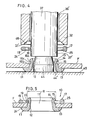
- the tool shown in Figure 1 and generally designated 30 comprises an elongated cylindrical body or tube 31 having a reduced diameter portion 32 at one or probe end and a handle portion 33 threadedly engaged as at 34 with the other end of the tube 31.
- the tube 31 has an inner peripheral wall 35 defining an elongated circular chamber 36 for accomodating therein a guide pin 37.
- the guide pin 37 has adjacent its opposite ends a pair of annular grooves 38, 39 receiving therein O-rings 40, 41, respectively, which O-rings are fitted in peripheral engagement with the inner peripheral wall 35 of the tube 31, providing a clearance 36' between the guide pin 37 and the wall 35 of the tube 31.
- Each 0-ring 40 (41) is made of a suitable resilient material such as rubber such that the guide pin 37 may be held resiliently in place within the chamber 36.
- a spring member 42 is provided in the chamber 36 between the threaded end of the handle portion 33 and the end of the guide pin 37 adjacent to the O-ring 41 to normally bias the pin 37 toward the probe end of the tube 31 or downwardly as viewed in Figure 1.
- a peripheral ledge 43 is formed integrally with the wall 35 of the tube 31 to project radially inwardly, which ledge 43 is disposed for abutting engagement with the O-ring 40 to limit descending movement of the guide pin 37.
- the guide pin 37 has a washer retainer 37' exposed beyond the reduced diameter portion 32 of the tube 31, the washer retainer 37' being diametrically slightly larger than the inside diameter r of the washer 17.
- An eyelet retainer 44 is provided integral with the washer retainer 37' and axially projecting from the guide pin 37, which eyelet retainer 44 is dimensioned to fit into the centre bore 11 of the eyelet 11.
- the retainer 44 has an inwardly tapered portion 44 ' for purposes to be hereafter described.
- the washer 17 is mounted on the guide pin 37 by manually fitting it around the washer retainer 37' of the pin 37, in which instance the washer 17 is retained securely because its diameter r is slightly smaller than the diameter of the washer retainer 37'.
- the tool 30 thus carrying the washer 17 is manipulated to pass the eyelet retainer 44 through the bore 11' of the eyelet 11 which has been previously set in an opening of a sheet of fabric F disposed on a working bed 45, as illustrated in Figure 4.
- the tool 30 is now pressed downwardly with the eyelet retainer 44 borne against the bed 45, so that the guide pin 37 ascends relatively to the body 31 within the chamber 36 against the force of the spring 42.
- the presence of the resilient O-rings 40, 41 on the guide pin 39 permits the pin 37 to move slant- ingly relative to the tube 31 during assembly of the washer 17 and the eyelet 11, or stated otherwise, the tube 31 tilts in sliding contact with the O-rings 40, 41 and so does progressively starting with areas of least slide resistance so that the locking tongues 19 can be snapped into engagement with the locking flange 14 progressively in the order in which the series of tongues 19 are more receptive to the flange 14, and hence much less coupling pressure is required than would be with the case where the guide pin 37 is directly engaged with the tube 31, because in the latter case, all of the locking tongues 19 are subject to uniform pressure to deform simultaneously, requiring more power to manipulate the tool 30.
Landscapes
- Engineering & Computer Science (AREA)
- Textile Engineering (AREA)
- Insertion Pins And Rivets (AREA)
- Dowels (AREA)
- Hand Tools For Fitting Together And Separating, Or Other Hand Tools (AREA)
- Footwear And Its Accessory, Manufacturing Method And Apparatuses (AREA)
- Treatment Of Fiber Materials (AREA)
Claims (4)
Applications Claiming Priority (2)
| Application Number | Priority Date | Filing Date | Title |
|---|---|---|---|
| JP144463/80U | 1980-10-09 | ||
| JP14446380U JPS588455Y2 (ja) | 1980-10-09 | 1980-10-09 | 鳩目取付治具 |
Publications (2)
| Publication Number | Publication Date |
|---|---|
| EP0050004A1 EP0050004A1 (de) | 1982-04-21 |
| EP0050004B1 true EP0050004B1 (de) | 1984-04-18 |
Family
ID=15362850
Family Applications (1)
| Application Number | Title | Priority Date | Filing Date |
|---|---|---|---|
| EP19810304659 Expired EP0050004B1 (de) | 1980-10-09 | 1981-10-07 | Hilfsmittel zum Anbringen von Ösen |
Country Status (6)
| Country | Link |
|---|---|
| EP (1) | EP0050004B1 (de) |
| JP (1) | JPS588455Y2 (de) |
| AU (1) | AU528810B2 (de) |
| CA (1) | CA1170223A (de) |
| DE (1) | DE3163228D1 (de) |
| ES (1) | ES268780Y (de) |
Cited By (1)
| Publication number | Priority date | Publication date | Assignee | Title |
|---|---|---|---|---|
| DE102013109812B3 (de) * | 2013-09-09 | 2014-12-11 | William Prym Gmbh & Co. Kg | Werkzeug zur Anbringung von Nietelementen an einem Flächenelement und Befestigungssystem hierzu |
Families Citing this family (6)
| Publication number | Priority date | Publication date | Assignee | Title |
|---|---|---|---|---|
| AU559902B1 (en) * | 1985-08-13 | 1987-03-26 | Ykk Corporation | Button holder/die assembly in button attaching device |
| GB2185003A (en) * | 1986-01-03 | 1987-07-08 | Eurobung Limited | Bung removal tool |
| JP6054228B2 (ja) * | 2013-03-29 | 2016-12-27 | Ykk株式会社 | ハトメ取付装置 |
| US20150007412A1 (en) * | 2013-07-02 | 2015-01-08 | Patagonia, Inc. | System and method for thermally bonding grommets to fabric |
| RU2660516C2 (ru) * | 2016-12-27 | 2018-07-06 | Глеб Владимирович Белич | Устройство для установки люверсов |
| RU174214U1 (ru) * | 2017-01-09 | 2017-10-06 | Глеб Владимирович Белич | Устройство для установки люверсов |
Family Cites Families (4)
| Publication number | Priority date | Publication date | Assignee | Title |
|---|---|---|---|---|
| US1438692A (en) * | 1921-02-16 | 1922-12-12 | G W J Murphy Company | Tool for setting fastener parts |
| US2177232A (en) * | 1937-08-27 | 1939-10-24 | Albert H Tinnerman | Tool |
| US3918140A (en) * | 1974-04-29 | 1975-11-11 | Anthony N Konstant | Snap-fastener setting tool |
| US3964660A (en) * | 1975-03-13 | 1976-06-22 | Hensley Donald W | Snap attaching tool |
-
1980
- 1980-10-09 JP JP14446380U patent/JPS588455Y2/ja not_active Expired
-
1981
- 1981-09-22 AU AU75557/81A patent/AU528810B2/en not_active Ceased
- 1981-09-26 ES ES1981268780U patent/ES268780Y/es not_active Expired
- 1981-10-07 DE DE8181304659T patent/DE3163228D1/de not_active Expired
- 1981-10-07 EP EP19810304659 patent/EP0050004B1/de not_active Expired
- 1981-10-09 CA CA000387635A patent/CA1170223A/en not_active Expired
Cited By (2)
| Publication number | Priority date | Publication date | Assignee | Title |
|---|---|---|---|---|
| DE102013109812B3 (de) * | 2013-09-09 | 2014-12-11 | William Prym Gmbh & Co. Kg | Werkzeug zur Anbringung von Nietelementen an einem Flächenelement und Befestigungssystem hierzu |
| EP2853167A1 (de) | 2013-09-09 | 2015-04-01 | William Prym GmbH & Co. KG | Werkzeug zur Anbringung von Nietelementen an einem Flächenelement und Befestigungssystem hierzu |
Also Published As
| Publication number | Publication date |
|---|---|
| EP0050004A1 (de) | 1982-04-21 |
| ES268780Y (es) | 1983-12-16 |
| JPS588455Y2 (ja) | 1983-02-15 |
| CA1170223A (en) | 1984-07-03 |
| ES268780U (es) | 1983-06-01 |
| DE3163228D1 (en) | 1984-05-24 |
| JPS5768766U (de) | 1982-04-24 |
| AU528810B2 (en) | 1983-05-12 |
| AU7555781A (en) | 1982-04-22 |
Similar Documents
| Publication | Publication Date | Title |
|---|---|---|
| US4481696A (en) | Snap-fit button | |
| US4397061A (en) | Grommet for setting in sheet material | |
| EP0081148A1 (de) | Druckknopf für Kleidung | |
| US5435043A (en) | Female member of snap button and press tool for clinching the same to washer | |
| US4831694A (en) | Buckle having external finger grip | |
| EP0243331B1 (de) | Form- und Dichtungsring | |
| EP0220624B1 (de) | Knopfbefestigung | |
| EP0050004B1 (de) | Hilfsmittel zum Anbringen von Ösen | |
| US4568215A (en) | Laterally adjustable fastening assembly | |
| EP0228656B1 (de) | Seilklemme | |
| CA1146340A (en) | Fabric-covered button | |
| EP0425230B1 (de) | Rohrkupplung | |
| EP0191424B1 (de) | Druckknopf | |
| GB2109454A (en) | Ball joint | |
| EP0101940A1 (de) | Befestigungselement für einen Schnappverschluss | |
| US5970588A (en) | Unlockable snap fastener | |
| US11592131B2 (en) | Fluid connecting device, in particular for the ventilation of a transmission casing | |
| US5470165A (en) | Retaining bushing for joining bearing rings | |
| EP0169660B1 (de) | Knopf | |
| EP0300660B1 (de) | Kettenwirbel | |
| GB2111156A (en) | Grommet or eyelet | |
| US4562626A (en) | Snap fastener and method of attaching same | |
| US4815173A (en) | Open-faced button | |
| EP0540223B1 (de) | Zierknopfkörper mit Verschluss und dessen Herstellungsverfahren | |
| CA1278170C (en) | Snap-fit button |
Legal Events
| Date | Code | Title | Description |
|---|---|---|---|
| PUAI | Public reference made under article 153(3) epc to a published international application that has entered the european phase |
Free format text: ORIGINAL CODE: 0009012 |
|
| AK | Designated contracting states |
Designated state(s): BE DE FR GB IT |
|
| ITCL | It: translation for ep claims filed |
Representative=s name: JACOBACCI CASETTA & PERANI S.P.A. |
|
| 17P | Request for examination filed |
Effective date: 19820723 |
|
| DET | De: translation of patent claims | ||
| ITF | It: translation for a ep patent filed | ||
| GRAA | (expected) grant |
Free format text: ORIGINAL CODE: 0009210 |
|
| AK | Designated contracting states |
Designated state(s): BE DE FR GB IT |
|
| REF | Corresponds to: |
Ref document number: 3163228 Country of ref document: DE Date of ref document: 19840524 |
|
| ET | Fr: translation filed | ||
| PGFP | Annual fee paid to national office [announced via postgrant information from national office to epo] |
Ref country code: FR Payment date: 19840829 Year of fee payment: 4 |
|
| PGFP | Annual fee paid to national office [announced via postgrant information from national office to epo] |
Ref country code: BE Payment date: 19840930 Year of fee payment: 4 |
|
| PGFP | Annual fee paid to national office [announced via postgrant information from national office to epo] |
Ref country code: DE Payment date: 19841221 Year of fee payment: 4 |
|
| PLBE | No opposition filed within time limit |
Free format text: ORIGINAL CODE: 0009261 |
|
| STAA | Information on the status of an ep patent application or granted ep patent |
Free format text: STATUS: NO OPPOSITION FILED WITHIN TIME LIMIT |
|
| 26N | No opposition filed | ||
| PG25 | Lapsed in a contracting state [announced via postgrant information from national office to epo] |
Ref country code: BE Effective date: 19861031 |
|
| BERE | Be: lapsed |
Owner name: YOSHIDA KOGYO K.K. Effective date: 19861031 |
|
| PG25 | Lapsed in a contracting state [announced via postgrant information from national office to epo] |
Ref country code: FR Free format text: LAPSE BECAUSE OF NON-PAYMENT OF DUE FEES Effective date: 19870630 |
|
| GBPC | Gb: european patent ceased through non-payment of renewal fee | ||
| PG25 | Lapsed in a contracting state [announced via postgrant information from national office to epo] |
Ref country code: DE Effective date: 19870701 |
|
| REG | Reference to a national code |
Ref country code: FR Ref legal event code: ST |
|
| PG25 | Lapsed in a contracting state [announced via postgrant information from national office to epo] |
Ref country code: GB Effective date: 19881118 |