EP0049986A1 - Elektrischer Motor - Google Patents
Elektrischer Motor Download PDFInfo
- Publication number
- EP0049986A1 EP0049986A1 EP81304599A EP81304599A EP0049986A1 EP 0049986 A1 EP0049986 A1 EP 0049986A1 EP 81304599 A EP81304599 A EP 81304599A EP 81304599 A EP81304599 A EP 81304599A EP 0049986 A1 EP0049986 A1 EP 0049986A1
- Authority
- EP
- European Patent Office
- Prior art keywords
- rotor
- power supply
- stator
- contact
- commutator
- Prior art date
- Legal status (The legal status is an assumption and is not a legal conclusion. Google has not performed a legal analysis and makes no representation as to the accuracy of the status listed.)
- Ceased
Links
- 230000001360 synchronised effect Effects 0.000 claims abstract description 38
- 230000007246 mechanism Effects 0.000 claims abstract description 23
- 238000013459 approach Methods 0.000 claims abstract description 5
- 238000006073 displacement reaction Methods 0.000 claims description 4
- 238000010586 diagram Methods 0.000 description 2
- 230000005611 electricity Effects 0.000 description 2
- 230000004907 flux Effects 0.000 description 2
- 230000001133 acceleration Effects 0.000 description 1
- 238000006243 chemical reaction Methods 0.000 description 1
- 230000008030 elimination Effects 0.000 description 1
- 238000003379 elimination reaction Methods 0.000 description 1
- 239000012212 insulator Substances 0.000 description 1
- 230000005405 multipole Effects 0.000 description 1
- 239000007858 starting material Substances 0.000 description 1
Images




Classifications
-
- H—ELECTRICITY
- H02—GENERATION; CONVERSION OR DISTRIBUTION OF ELECTRIC POWER
- H02K—DYNAMO-ELECTRIC MACHINES
- H02K21/00—Synchronous motors having permanent magnets; Synchronous generators having permanent magnets
- H02K21/02—Details
-
- H—ELECTRICITY
- H02—GENERATION; CONVERSION OR DISTRIBUTION OF ELECTRIC POWER
- H02K—DYNAMO-ELECTRIC MACHINES
- H02K11/00—Structural association of dynamo-electric machines with electric components or with devices for shielding, monitoring or protection
- H02K11/20—Structural association of dynamo-electric machines with electric components or with devices for shielding, monitoring or protection for measuring, monitoring, testing, protecting or switching
- H02K11/21—Devices for sensing speed or position, or actuated thereby
- H02K11/23—Mechanically-actuated centrifugal switches
Definitions
- the present invention relates to synchronous motors, more particularly to those synchronous motors which comprise a permanent-magnet-containing rotor and a stator, which, at start-up, use rectifiers and a commutator comprising sliders and brushes to supply the stator with only the rectified component of the AC power supply, and which are provided with a mechanical conversion device which, when the rotor has reached nearly synchronous speed, switches the AC supply directly to the stator coils.
- a device of this kind is given by Gianni A. Dotto et al., "SYNCHRONOUS MOTOR STARTER CIRCUIT EMPLOYING COMMUTATOR AND RECTIFIER DURING STARTING", U.S.P. 3394296; which consists essentially of a permanent-magnet-type inner rotor and an outer stator, which, at start-up, use rectifiers and a commutator comprising sliders and brushes to supply the stator with only the rectified component of the AC power supply, and which, when the rotation of the rotor has reached the synchronous rotation, allows a centrifugal switch provided in the circuit to short the circuit so as to supply the stator directly with the AC power supply.
- a synchronous motor which has a permanent-magnet rotor, a stator, rectifiers for converting the AC power supply into rectified current, and a commutator for switching the direction of current as the rotor rotates during start-up, and means for switching the AC supply directly to the stator when the rotor approaches synchronous speed;
- the commutator comprises a rotary component which rotates with the rotor and engages fixed elements for effecting switching of the current but is axially displaceable to release it from contact with said elements, and means are provided for effecting said displacement when the rotor approaches synchronous speed, said displacement allowing the AC current to be supplied directly to the stator.
- the synchronous motors of the present invention are exemplified in the following description with reference to the drawings. Two selected embodiments are given: (1) a motor in which the starting mechanism comprises stationary rectifiers for the starting mechanism located in a circuit and a commutator consisting of a circular cam rotary in union with the rotor shaft, and stationary contact switches; (2) a motor in which the starting mechanism comprises a commutator consisting of stationary brushes and sliders rotary in union with the rotor shaft, and rectifiers located within the sliders and rotating in union with the rotor shaft.
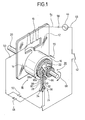
- FIG. 1 is a schematic diagram illustrating the operating principle of a 2-pole single-phase synchronous motor to which the present invention has been applied.
- the motor possesses a 2-pole stator 12 with coil 10; a 2-pole permanent magnet 14 generating the field and carried by the rotor 18 which has a centrifugal switch 16 incorporated inside; a rotor shaft 20 supporting rotor 18 rotatable in a bearing (not shown) between the poles of stator 12; and a commutator 26.
- Commutator 26 consists of a cam 22 and external stationary contact switches 24 which contact the cam 22.
- Contact switch 24 comprises three contact plate springs 28, 30 and 32 electrically separated by insulators 34 and 36, and having contacts 38 and 40 between springs 28 and 30 and springs 30 and 32, respectively.
- Spring 30 is connected to terminal 46 of the single-phase AC power supply 44 via the power supply switch 42;
- spring 28 is connected to terminal 50 of coil 10 via diode 48 with the polarity as shown; and spring 32 is connected also to terminal 50 via diode 52 opposite to diode 48 in polarity.
- the other terminal 54 of coil 10 is connected to the other terminal 56 of AC power supply 44.
- cam 22 has a first elevated part 60 covering a circumferential angle of almost 180° and a second elevated part .62 covering almost the other 180° angle, the part 62 having twice the elevation of the part 60.
- the elevated parts are concentric and are located in two adjacent orbitals, the first elevated part 60 extending into both orbitals but the second elevated part 62 being confined on one of the orbitals.
- the elevated part 62 in its orbital terminates short of the elevated part 60 in the other orbital so that there are non-overlapping regions 64a and 64b on opposite sides of the circumference of the cam.
- the contact plate spring 28 has its tip 28a assuming an L-shape as shown in Figure 1 and is designed to be in sliding contact with the elevated part 62 of cam 22 and to be displaced thereby to the left as shown in Figures 2A, 2B, 3A and 3B.
- Spring 30 also has its tip 30a formed as an L-shape and is designed to be in sliding contact in the adjacent orbital with the elevated part 60 of the cam 22 and to be displaced thereby to the left as shown in Figure 3A and engages spring 28 by contact 38.
- Each of springs 28, 30 and 32 is biased to the right as shown in Figure 3A and spring 32 is restrained by stop 66.
- Spring 28 has its base overlapping that of spring 30 but is bent laterally in the region of the tip 28a so as to be located on the orbital of the elevated part 62. Therefore, when cam 22 is positioned as shown in Figures 2A and.3A, contact 38 makes and contact 40 breaks; whereas when cam 22 is positioned as shown in Figures 2B and 3B, contact 38 breaks and contact 40 makes.
- Gaps 64a and 64b between the elevated parts 60 and 62 of cam 22 are designed in such a way that, when the tip 30a of spring 30 comes on each gap, both the contacts 38 and 40 are made and connect both the diodes 48 and 52 to the AC power supply 44. This is to allow coil 10 to be sufficiently excited even if the rotor 18 has to start at this position.
- the relative position of rotor 18 and switching mechanism 26 is determined in such a way that, when pole N of rotor 18 faces pole 60 of stator 12, the contact of switch 24 is positioned between the state of Figure 3A and that of Figure 3B, i.e. springs 28a and 30a are positioned on gap 64a.
- centrifugal switch 16 When the motor reaches the synchronous working state, centrifugal switch 16 is put into operation at a prescribed rotary speed close to the rotary speed for the power supply frequency to shift cam 22 axially in the direction of arrow 70.
- the centrifugal switch will later be described in detail with respect to its structure and operation.
- both the diodes 48 and 52 are connected to terminal 46 of AC power supply 44, causing no switching operation to be effected.
- the rotary magnetic field produced by stator 12 keeps rotor 18 in the synchronous working state, i.e. this motor operates completely as an ordinary synchronous motor.
- the point at which centrifugal switch 16 comes into operation may be within an interval extending to the synchronous speed for the power supply frequency, provided the synchronous working state can be reached ultimately.
- centrifugal switch 16 On the outer circumference of casing 72 fixed to rotor shaft 20 the permanent magnet 14 is inset and secured, forming rotor 18.
- Cam 22, rotary in union with rotor shaft 20, is accommodated in a part 74 which is located in and rotary in union with casing 72, so as to be movable in the axial direction of rotor shaft 20.
- Part 74 comprises an outer cylinder 76 and an inner cylinder 78.
- a coil spring 84 extending axially is inserted between the left end 80 of inner cylinder 78 and shoulder 82 in a cavity of cam 22, so that cam 22 is biased leftward in the figure away from rotor 18.
- the bottom 86 of the cavity of cam 22 has the working end 90 of a pair of weights 88 contacting it as shown in the figure.
- the weight 88 comprises a weighted portion 92 and a fulcrum 94 which is in contact with projection 96 of part 76.
- a 2-pole single-phase synchronous motor has been described as an embodiment of the present invention.
- This technology is also applicable to 2n-pole synchronous motors where n is an integer equal to or more than 2.
- the mechanism comprises two cam sections; the first cam section covering a rotary angle of ca. 360 0 /2n closes the first contact and opens the second, thereby connecting the AC power supply to one of first and second rectifying mechanisms; and the second cam section covering 360°/2n opens the first contact and closes the second, thereby connecting the AC power supply to the other one of said first and second rectifying mechanisms.
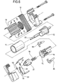
- the cam mechanism may be formed with axial projections as shown in Fig. 5; or any other cam mechanism may be provided which is capable of effecting the required operation of the contacting mechanism on rotation.
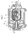
- FIG 7 is an exploded cross-sectional view of a 2-pole single-phase synchronous motor.
- 110 is an annular 2-pole permanent-magnet rotor, which has a cap 112 to shield the magnetic flux and rotate in union with rotor shaft 114.
- a 2-pole stator 116 is fixed to bearing 118 of rotor shaft 114 with bolts 119 and is located in the space between the rotor shaft 114 and rotor 110.
- a slider 120 is divided circumferentially 180° apart, and is capable of free sliding in the axial direction, and is urged to the left by spring 122.
- Weights 124 are accommodated within a case 126, and has their inner ends hooked on L-shaped ends 130 of connecting sections 128 extending from slider 120 toward case 126, so that the weights can pivot about the ends 130.
- a brush 132 is in sliding contact with slider 120 at the time of starting.
- the slider.120 comprises slider pieces 120a and 120b each of which extends almost 180° about rotor shaft 114.
- rectifier 134 which connects slider pieces 120a and 120b with the conductive direction from slider piece 120a to 120b.
- Brush 132 consists of brush elements 132a and 132b, which are in sliding contact with slider pieces 120a and 120b, respectively.
- Slider guides 136 fit keyway sections 138 so as to allow slider 120 to rotate in union with rotor shaft 114 but to slide freely in the axial direction.
- the slider pieces 120a and 120b have taper sections 140a and 140b, respectively, leading to step section 142.
- Figure 9 illustrates the state where the rotor 110 has approached the synchronous speed with resultant outward pivoting of weights 124 by centrifugal force.
- the weights 124 are designed to begin to open outwards at a prescribed rotor speed. Opening of weights 124 will cause the weights 124 to pivot around the L-shaped ends 130 of connecting sections 128 and at the same time to move from contacting the radial end wall of case 126 to contacting the circumferential outer wall. This in turn causes slider 120 via connecting section 128 to be pulled toward stator 116 (to the right) against the pressure of spring 122. When slider 120 is displaced axially, brushes 132a and 132b having been in sliding contact with slider pieces 120a and 120b will come opposite the stepped section 142 of slider 120.
- Figure 10 shows brush 132 in its conductive state, where slider 120 is pulled in, brushes 132a and 132b are out of contact with slider pieces 120a and 120b, and the upper contact sections 133a and 133b are in contact with each other by reason of the diameter of the stepped section 142 being less than the spacing of the brush elements 132a,132b.
- Figure 11 illustrates an alternative embodiment of slider 120 for brush 132.
- Slider 120 is tapered, becoming smaller in the disengaging direction.' It is desired that the brush (not shown) has the same slope as the tapered section so as to be capable of tight contact with the larger-diameter part of the tapered section.
- the embodiments described above relate to single-phase AC power supply.
- case 126 has a sirocco fan united with it, and case 126 together with slider 20 is made slidable in the axial direction and pushed opposite to the urging of the fan by spring 122. Rotation of the fan at a speed exceeding a prescribed value produces a negative pressure inside case 126 so as to attract case 126 to the right and displace the slider 120.
- a screw fan is provided on the outer side of case 126 and rotation of the screw fan at a speed exceeding a prescribed value causes the fan to advance to the right and displace the slider 120.
- motors may be produced of smaller size and higher efficiency and since, when the speed of motor has approached synchronous operation, the autostart mechanism is completely released, resulting in elimination of mechanical and electrical resistance on the switching mechanism, no generation of spark due to the brush sliding, no damage to sliding parts,-and no noise generation from sliding parts.
- the present invention is effective to making the motor smaller and lighter and to lowering the cost, since the permanent-magnet rotor positioned outside surrounds the stator placed inside with reduced magnetic flux leakage and increased magnetic efficiency, and a smaller rotor is required than with a permanent-magnet rotor placed inside.
Landscapes
- Engineering & Computer Science (AREA)
- Power Engineering (AREA)
- Microelectronics & Electronic Packaging (AREA)
- Permanent Magnet Type Synchronous Machine (AREA)
Applications Claiming Priority (4)
| Application Number | Priority Date | Filing Date | Title |
|---|---|---|---|
| JP142294/80 | 1980-10-11 | ||
| JP14229480A JPS5795168A (en) | 1980-10-11 | 1980-10-11 | Self-startable revolving-field type synchronous motor |
| JP407881A JPS57119664A (en) | 1981-01-14 | 1981-01-14 | Outside rotor type motor |
| JP4078/81 | 1981-01-14 |
Publications (1)
| Publication Number | Publication Date |
|---|---|
| EP0049986A1 true EP0049986A1 (de) | 1982-04-21 |
Family
ID=26337799
Family Applications (1)
| Application Number | Title | Priority Date | Filing Date |
|---|---|---|---|
| EP81304599A Ceased EP0049986A1 (de) | 1980-10-11 | 1981-10-05 | Elektrischer Motor |
Country Status (2)
| Country | Link |
|---|---|
| US (1) | US4395668A (de) |
| EP (1) | EP0049986A1 (de) |
Families Citing this family (7)
| Publication number | Priority date | Publication date | Assignee | Title |
|---|---|---|---|---|
| JP2556964B2 (ja) * | 1985-11-14 | 1996-11-27 | 株式会社ゼクセル | 内燃機関用アイドル運転制御装置 |
| US4978819A (en) * | 1989-07-24 | 1990-12-18 | Emerson Electric Co. | Electric machinery switch assembly |
| US5602957A (en) * | 1993-06-07 | 1997-02-11 | General Electric Company | Permanent magnet direct current motor |
| US5744883A (en) * | 1997-01-22 | 1998-04-28 | Emerson Electric Co. | Contoured switch lever for centrifugal switch |
| US6982507B2 (en) * | 2004-01-14 | 2006-01-03 | A. O. Smith Corporation | Electric motor assembly with a module attached to a motor housing |
| CN104079135A (zh) * | 2014-07-24 | 2014-10-01 | 王强 | 一种分体式无刷电机 |
| CN113783368A (zh) * | 2021-08-12 | 2021-12-10 | 江苏航天动力机电有限公司 | 一种带有变频器的泵用永磁电机 |
Citations (5)
| Publication number | Priority date | Publication date | Assignee | Title |
|---|---|---|---|---|
| FR383328A (fr) * | 1906-11-03 | 1908-03-05 | Westinghouse Electric Corp | Perfectionnements dans les moteurs à courant alternatif |
| US1631102A (en) * | 1927-05-31 | leake | ||
| DE1082972B (de) * | 1954-03-13 | 1960-06-09 | Standard Elektrik Lorenz Ag | Gleichstromdrehfeldkleinstmotor, insbesondere fuer Funkanlagen |
| US3014142A (en) * | 1958-02-06 | 1961-12-19 | Lee Royal | Synchronous dynamo-electric machines |
| US3394296A (en) * | 1966-05-31 | 1968-07-23 | Mallory & Co Inc P R | Synchronous motor stator circuit employing commutator and rectifier during starting |
-
1981
- 1981-10-05 EP EP81304599A patent/EP0049986A1/de not_active Ceased
- 1981-10-06 US US06/308,956 patent/US4395668A/en not_active Expired - Fee Related
Patent Citations (5)
| Publication number | Priority date | Publication date | Assignee | Title |
|---|---|---|---|---|
| US1631102A (en) * | 1927-05-31 | leake | ||
| FR383328A (fr) * | 1906-11-03 | 1908-03-05 | Westinghouse Electric Corp | Perfectionnements dans les moteurs à courant alternatif |
| DE1082972B (de) * | 1954-03-13 | 1960-06-09 | Standard Elektrik Lorenz Ag | Gleichstromdrehfeldkleinstmotor, insbesondere fuer Funkanlagen |
| US3014142A (en) * | 1958-02-06 | 1961-12-19 | Lee Royal | Synchronous dynamo-electric machines |
| US3394296A (en) * | 1966-05-31 | 1968-07-23 | Mallory & Co Inc P R | Synchronous motor stator circuit employing commutator and rectifier during starting |
Also Published As
| Publication number | Publication date |
|---|---|
| US4395668A (en) | 1983-07-26 |
Similar Documents
| Publication | Publication Date | Title |
|---|---|---|
| GB2220681A (en) | Laundering apparatus directly driven by a salient pole electronically commutated motor | |
| EP0049986A1 (de) | Elektrischer Motor | |
| US12074004B2 (en) | Self-powered recloser | |
| KR101503062B1 (ko) | 정지축을 구비한 브러시리스 전기장치 및 그 제조방법 | |
| SU1399854A1 (ru) | Коллекторный генератор посто нного тока | |
| RU2421865C1 (ru) | Однофазный электродвигатель | |
| KR20200112501A (ko) | 권선 절환 가능한 전동기 | |
| KR20100110041A (ko) | 모터의 원심스위치구조 | |
| RU2091966C1 (ru) | Машина постоянного тока и.г.скибицкого | |
| EP0494611B1 (de) | Anker für eine drehende elektrische Maschine | |
| JPH09135559A (ja) | 同期モータ | |
| KR100511321B1 (ko) | 단상유도전동기용 원심스위치 | |
| EP0050456A1 (de) | Elektrischer Motor | |
| US20040164695A1 (en) | Electrodynamic machines and components therefor and methods of making and using same | |
| US4524293A (en) | 4-Pole electric motor | |
| US1194103A (en) | Alfred f | |
| RU2092924C1 (ru) | Тороидальная конструкция шихтованного пластинами магнитопровода с электрическими обмотками | |
| RU2267855C2 (ru) | Электродвигатель | |
| EP0670622A1 (de) | Elektrischer Motor | |
| JPH10313562A (ja) | 2極同期モータ | |
| US1011774A (en) | Centrifugal switch. | |
| SU1069083A1 (ru) | Бесконтактный вентильный электродвигатель | |
| SU1603516A1 (ru) | Электропривод переменного тока | |
| SU1050056A1 (ru) | Стартер-генератор | |
| KR100595727B1 (ko) | 단상유도전동기의 원심스위치 |
Legal Events
| Date | Code | Title | Description |
|---|---|---|---|
| PUAI | Public reference made under article 153(3) epc to a published international application that has entered the european phase |
Free format text: ORIGINAL CODE: 0009012 |
|
| AK | Designated contracting states |
Designated state(s): CH DE FR GB LI NL |
|
| 17P | Request for examination filed |
Effective date: 19821015 |
|
| RAP1 | Party data changed (applicant data changed or rights of an application transferred) |
Owner name: WATANUKI, TAKAO Owner name: KOMATSU, FUMITO Owner name: SANKYO SEIKI MFG. CO. LTD. |
|
| STAA | Information on the status of an ep patent application or granted ep patent |
Free format text: STATUS: THE APPLICATION HAS BEEN REFUSED |
|
| 18R | Application refused |
Effective date: 19850216 |
|
| RIN1 | Information on inventor provided before grant (corrected) |
Inventor name: KOMATSU, FUMITO |