EP0049698B1 - Releasing device in core barrel grapplers - Google Patents
Releasing device in core barrel grapplers Download PDFInfo
- Publication number
- EP0049698B1 EP0049698B1 EP81850182A EP81850182A EP0049698B1 EP 0049698 B1 EP0049698 B1 EP 0049698B1 EP 81850182 A EP81850182 A EP 81850182A EP 81850182 A EP81850182 A EP 81850182A EP 0049698 B1 EP0049698 B1 EP 0049698B1
- Authority
- EP
- European Patent Office
- Prior art keywords
- grappling
- sleeve
- core barrel
- drill rod
- grappling means
- Prior art date
- Legal status (The legal status is an assumption and is not a legal conclusion. Google has not performed a legal analysis and makes no representation as to the accuracy of the status listed.)
- Expired
Links
- 241000282472 Canis lupus familiaris Species 0.000 claims description 22
- 238000005553 drilling Methods 0.000 description 5
- 230000008878 coupling Effects 0.000 description 3
- 238000010168 coupling process Methods 0.000 description 3
- 238000005859 coupling reaction Methods 0.000 description 3
- 238000000034 method Methods 0.000 description 2
- 230000006835 compression Effects 0.000 description 1
- 238000007906 compression Methods 0.000 description 1
- 230000006378 damage Effects 0.000 description 1
- 230000001419 dependent effect Effects 0.000 description 1
- 238000006073 displacement reaction Methods 0.000 description 1
Images
Classifications
-
- E—FIXED CONSTRUCTIONS
- E21—EARTH OR ROCK DRILLING; MINING
- E21B—EARTH OR ROCK DRILLING; OBTAINING OIL, GAS, WATER, SOLUBLE OR MELTABLE MATERIALS OR A SLURRY OF MINERALS FROM WELLS
- E21B25/00—Apparatus for obtaining or removing undisturbed cores, e.g. core barrels or core extractors
- E21B25/02—Apparatus for obtaining or removing undisturbed cores, e.g. core barrels or core extractors the core receiver being insertable into, or removable from, the borehole without withdrawing the drilling pipe
Definitions
- the present invention relates to a device for releasing a grappling means from a core barrel when the grappling means and the core barrel, which are connected by connecting means, have been lowered to the bottom of a hollow drill rod string.
- grappling means Before drilling commences the grappling means must be disengaged from the core barrel at the bottom of the string in its working position and pulled up out of the string.
- Prior art devices for disengaging the grappling means from the core barrel are burdened with several disadvantages. Most of them are released, when the core barrel is in its working position and axially latched by latching dogs, by pulling heavily on the wire.
- a device which disengages the grappling means from the core barrel with the aid of a sleeve which is movable axially on the grappling means (see US-A-3 701 389).
- the primary drawback with this device is that it may release the means coupling the grappling means and core barrel before the barrel has arrived at its working position in the bottom drill rod if the barrel comes against something projecting into the drill rod bore during lowering of the barrel.
- the object of the present invention is to provide a device of the kind mentioned in the first part of claim 1, by means of which the drawbacks of previously known devices have been circumvented.
- the foremost advantages of the invented device is that it can release the means connecting the grappling means and core barrel only when the barrel is at a predetermined distance from, or assumes a working position in the bottom drill rod, and that it is actuated by a recess in the wall of the bottom drill rod.
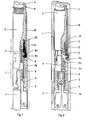
- FIG. 1 The upper portion of a rotatable drill rod string denoted by the numeral 1 is illustrated in Figure 1.
- Figures 1-3 there is illustrated the upper portion of a conventional core barrel 2, e.g. of the kind illustrated in US-A-3 701 389, and intended for lowering in the string to assume a working position in the bottom section thereof, which is provided with a drill bit.
- a grappling means provided with a long wire or cable is used to lower the core barrel 2 to its working position, this wire also being used to pull up the barrel from the string when drilling is stopped.
- Only a lower portion of this grappling means, denoted bythe numeral 3, is illustrated in Figures 1-3, this portion being removably connected by means of a screw thread to the remaining portion 4 of the grappling means, which is of a conventional configuration.
- the lower portion of the grappling means 3 is coupled to the upper portion of the core barrel 2 by means of spring-biased locking jaws 5, swivelably mounted on the core barrel, engaging with an inwardly directed flange 6 on the lower, sleeve-shaped portion 3a of the grappling means. This connection is made before the barrel is inserted in the string.
- the barrel 2 and grappling means 3 can now be lowered into the drill rod string 1.
- the dogs 9 glide along and press against the bore of the string and can therefore not release the disengagement sleeve 8, not even if the grappling means 3 assumes a decentralised position in the string, since at least one of the three dogs always retains its grip on the projection 8a.
- the dogs 9 leave their retaining position around the sleeve 8, and be moved into an annular recess 13 in the bore of the bottom drill rod.
- the outwardly directed movement of the dogs 9 is achieved by the pressure of the projection 8a against the surfaces 9a provided by the spring 7.
- the sleeve 8 When the projection 8a leaves the dogs 9, the sleeve 8 is displaced downwardly inside the grappling means 3 and is inserted between the locking jaws 5 and the sleeve portion 3a so that the jaws are displaced radially inwards against spring bias. Immediately after the sleeve 8 has left the dogs 9, these are displaced radially inwards by the action of the force in the elastic 0 ring 12. The downward movement of the sleeve 8 continues until its bottom edge rests against the upper side of the flange 6. This condition is illustrated in Fig. 2.
- the grappling means 3 can now be pulled up with the aid of the wire attached to its upper portion, since the sleeve 8 has inhibited the coupling grip between the grappling means and the core barrel.
- the locking jaws 5 glide against the inner surface of the sleeve 8 and cannot engage with the flange 6, since the inner diameter of the sleeve is somewhat less than the inner diameter of the flange.
- Fig. 3 the grappling means 3 is shown disengaged and in a position at a distance from the core barrel 2.
- the locking jaws 5 of the barrel are also shown in the figure, after they have left the grappling means and have swung radially outwards, and the latching means 5b thereon have been inserted under a shoulder 14 in the bottom drill rod to prevent the axial displacement of the barrel upwards from its working position during drilling.
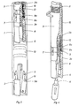
- the sleeve 8 When the grappling means 3 has been taken up out of the string, the sleeve 8 is pressed upwards against the bias of the spring 7 by some suitable tool, e.g. a screwdriver 15, in the manner shown in Fig. 4, until the projection 8a is accommodated in the recesses of the dogs 9, the sleeve 10 then being screwed downwards onto the grappling means until the sleeve has assumed the position shown by full lines in Fig. 4, where it prevents the dogs 9 from swinging radially outwards.
- the screwdriver 15 can then be removed and the grappling means lowered into the string 1 for connection to the core barrel 2, when it is desired to pull up the latter from the string.
- the sleeve 10 assumes the attitude shown by full lines in Fig. 4, signifying that the sleeve 8 can never be displaced axially downwards relative the rest of the grappling means, not even when the dogs 9 are opposite the recess 13.
- the lower portion of the grappling means (the flange 6) strokes against the locking jaws 5 of the core barrel, the jaws are swung radially inwards from the position shown in Fig. 3 and taken into engagement with the flange 6 simultaneously as the latching portions 5b of said jaws are swung inwards and leave the shoulder 14.
- the grappling means is now connected to the barrel in the manner shown in Fig. 1 and can be pulled up from the drill rod string.
Landscapes
- Life Sciences & Earth Sciences (AREA)
- Engineering & Computer Science (AREA)
- Geology (AREA)
- Mining & Mineral Resources (AREA)
- Physics & Mathematics (AREA)
- Environmental & Geological Engineering (AREA)
- Fluid Mechanics (AREA)
- General Life Sciences & Earth Sciences (AREA)
- Geochemistry & Mineralogy (AREA)
- Earth Drilling (AREA)
- Drilling And Boring (AREA)
Applications Claiming Priority (2)
| Application Number | Priority Date | Filing Date | Title |
|---|---|---|---|
| SE8007045 | 1980-10-08 | ||
| SE8007045A SE423924B (sv) | 1980-10-08 | 1980-10-08 | Anordning for frikoppling av en fangstanordning fran ett kernror i ett borror |
Publications (3)
| Publication Number | Publication Date |
|---|---|
| EP0049698A2 EP0049698A2 (en) | 1982-04-14 |
| EP0049698A3 EP0049698A3 (en) | 1984-08-01 |
| EP0049698B1 true EP0049698B1 (en) | 1986-12-30 |
Family
ID=20341934
Family Applications (1)
| Application Number | Title | Priority Date | Filing Date |
|---|---|---|---|
| EP81850182A Expired EP0049698B1 (en) | 1980-10-08 | 1981-10-07 | Releasing device in core barrel grapplers |
Country Status (9)
| Country | Link |
|---|---|
| US (1) | US4431225A (enExample) |
| EP (1) | EP0049698B1 (enExample) |
| JP (1) | JPS5792294A (enExample) |
| AU (1) | AU539058B2 (enExample) |
| CA (1) | CA1182441A (enExample) |
| DE (1) | DE3175763D1 (enExample) |
| IN (1) | IN154260B (enExample) |
| SE (1) | SE423924B (enExample) |
| ZA (1) | ZA816909B (enExample) |
Families Citing this family (6)
| Publication number | Priority date | Publication date | Assignee | Title |
|---|---|---|---|---|
| US5041020A (en) * | 1990-07-10 | 1991-08-20 | Amp Incorporated | F series coaxial cable adapter |
| US5551196A (en) * | 1993-06-17 | 1996-09-03 | Rylock Company Ltd. | Window assembly having dead air spaces formed by non conductive members |
| RU2159321C1 (ru) * | 1999-04-13 | 2000-11-20 | Санкт-Петербургский государственный горный институт им. Г.В. Плеханова (Технический университет) | Распорный узел колонкового набора |
| DE102008002835B4 (de) | 2008-04-30 | 2012-09-06 | Universität Bremen vertreten durch den Rektor | Hakenfänger |
| CA2902642C (en) * | 2013-03-01 | 2020-12-29 | Sandvik Intellectual Property Ab | Overshot tool having latch control means |
| CN113513282B (zh) * | 2021-08-10 | 2022-08-05 | 中国船舶科学研究中心 | 一种深部原位岩芯抓取装置及其操作方法 |
Family Cites Families (8)
| Publication number | Priority date | Publication date | Assignee | Title |
|---|---|---|---|---|
| GB286101A (en) * | 1927-03-21 | 1928-03-01 | Matvey Alcunovitch Capeliushni | Bore-hole apparatus |
| US2948340A (en) * | 1954-07-09 | 1960-08-09 | Otis Eng Co | Well tools |
| US2893693A (en) * | 1957-09-11 | 1959-07-07 | Clark Wallace | Down-hole motor positioning device |
| US2980185A (en) * | 1958-07-11 | 1961-04-18 | Camco Inc | Retrievable well tool hanger |
| US3319719A (en) * | 1964-06-16 | 1967-05-16 | Perry J Decuir | Cam biased well anchor with detachable setting means |
| US3537743A (en) * | 1966-08-10 | 1970-11-03 | Boyles Bros Drilling Co | Core drilling system |
| US3441098A (en) * | 1966-08-10 | 1969-04-29 | Boyles Bros Drilling Co | Core drilling system |
| SE332402B (enExample) * | 1970-04-30 | 1971-02-08 | Atlas Copco Ab |
-
1980
- 1980-10-08 SE SE8007045A patent/SE423924B/sv not_active IP Right Cessation
-
1981
- 1981-10-05 US US06/308,529 patent/US4431225A/en not_active Expired - Fee Related
- 1981-10-06 ZA ZA816909A patent/ZA816909B/xx unknown
- 1981-10-06 AU AU76053/81A patent/AU539058B2/en not_active Ceased
- 1981-10-07 EP EP81850182A patent/EP0049698B1/en not_active Expired
- 1981-10-07 DE DE8181850182T patent/DE3175763D1/de not_active Expired
- 1981-10-08 CA CA000387561A patent/CA1182441A/en not_active Expired
- 1981-10-08 JP JP56161942A patent/JPS5792294A/ja active Pending
- 1981-10-17 IN IN1143/CAL/81A patent/IN154260B/en unknown
Also Published As
| Publication number | Publication date |
|---|---|
| JPS5792294A (en) | 1982-06-08 |
| EP0049698A2 (en) | 1982-04-14 |
| CA1182441A (en) | 1985-02-12 |
| ZA816909B (en) | 1982-09-29 |
| AU539058B2 (en) | 1984-09-06 |
| EP0049698A3 (en) | 1984-08-01 |
| DE3175763D1 (en) | 1987-02-05 |
| SE423924B (sv) | 1982-06-14 |
| US4431225A (en) | 1984-02-14 |
| AU7605381A (en) | 1982-04-22 |
| SE8007045L (sv) | 1982-04-09 |
| IN154260B (enExample) | 1984-10-13 |
Similar Documents
| Publication | Publication Date | Title |
|---|---|---|
| US4074912A (en) | Releasable rigid pile connector apparatus | |
| US4611953A (en) | TLP tendon bottom connector | |
| US4969514A (en) | Apparatus for retrieving pipe sections from a well bore | |
| CA1237665A (en) | Tubular member anchoring arrangement and method | |
| CA1285473C (en) | Latch and retrieving assembly | |
| GB1570725A (en) | Anchoring apparatus for use in well conduits | |
| GB2056530A (en) | Liner hanger and running and setting tool | |
| GB2159855A (en) | Method of and apparatus for cutting and recovering of submarine surface casing | |
| US2736384A (en) | Releasable coupling devices | |
| GB2203467A (en) | Well tool connector | |
| EP0049698B1 (en) | Releasing device in core barrel grapplers | |
| US2887162A (en) | Automatic releasable fishing apparatus | |
| US5092402A (en) | Tubing end locator | |
| US4262748A (en) | Remote multiple string well completion | |
| US3960399A (en) | Setting and retrieval device for down-hole equipment | |
| US4708524A (en) | Remote guideline connector | |
| US4927295A (en) | Retrievable guide post system | |
| US2128102A (en) | Overshot | |
| US4035011A (en) | Soft set running tool | |
| US4572289A (en) | Electric wireline packer retriever apparatus | |
| JPS58204292A (ja) | 井戸掘削装置 | |
| US4127297A (en) | Releasable overshot | |
| US3915489A (en) | Elevator plug | |
| CA1202887A (en) | Setting tool | |
| US2743130A (en) | Grappling tool |
Legal Events
| Date | Code | Title | Description |
|---|---|---|---|
| PUAI | Public reference made under article 153(3) epc to a published international application that has entered the european phase |
Free format text: ORIGINAL CODE: 0009012 |
|
| AK | Designated contracting states |
Designated state(s): BE DE FR GB IT NL |
|
| 17P | Request for examination filed |
Effective date: 19821013 |
|
| PUAL | Search report despatched |
Free format text: ORIGINAL CODE: 0009013 |
|
| AK | Designated contracting states |
Designated state(s): BE DE FR GB IT NL |
|
| GRAA | (expected) grant |
Free format text: ORIGINAL CODE: 0009210 |
|
| AK | Designated contracting states |
Kind code of ref document: B1 Designated state(s): BE DE FR GB IT NL |
|
| PG25 | Lapsed in a contracting state [announced via postgrant information from national office to epo] |
Ref country code: NL Effective date: 19861230 Ref country code: IT Free format text: LAPSE BECAUSE OF FAILURE TO SUBMIT A TRANSLATION OF THE DESCRIPTION OR TO PAY THE FEE WITHIN THE PRESCRIBED TIME-LIMIT;WARNING: LAPSES OF ITALIAN PATENTS WITH EFFECTIVE DATE BEFORE 2007 MAY HAVE OCCURRED AT ANY TIME BEFORE 2007. THE CORRECT EFFECTIVE DATE MAY BE DIFFERENT FROM THE ONE RECORDED. Effective date: 19861230 |
|
| REF | Corresponds to: |
Ref document number: 3175763 Country of ref document: DE Date of ref document: 19870205 |
|
| ET | Fr: translation filed | ||
| NLV1 | Nl: lapsed or annulled due to failure to fulfill the requirements of art. 29p and 29m of the patents act | ||
| PLBE | No opposition filed within time limit |
Free format text: ORIGINAL CODE: 0009261 |
|
| STAA | Information on the status of an ep patent application or granted ep patent |
Free format text: STATUS: NO OPPOSITION FILED WITHIN TIME LIMIT |
|
| 26N | No opposition filed | ||
| PGFP | Annual fee paid to national office [announced via postgrant information from national office to epo] |
Ref country code: FR Payment date: 19900910 Year of fee payment: 10 |
|
| PGFP | Annual fee paid to national office [announced via postgrant information from national office to epo] |
Ref country code: GB Payment date: 19900912 Year of fee payment: 10 |
|
| PGFP | Annual fee paid to national office [announced via postgrant information from national office to epo] |
Ref country code: BE Payment date: 19900927 Year of fee payment: 10 |
|
| PGFP | Annual fee paid to national office [announced via postgrant information from national office to epo] |
Ref country code: DE Payment date: 19900928 Year of fee payment: 10 |
|
| PG25 | Lapsed in a contracting state [announced via postgrant information from national office to epo] |
Ref country code: GB Effective date: 19911007 |
|
| PG25 | Lapsed in a contracting state [announced via postgrant information from national office to epo] |
Ref country code: BE Effective date: 19911031 |
|
| BERE | Be: lapsed |
Owner name: CRAELIUS A.B. Effective date: 19911031 |
|
| GBPC | Gb: european patent ceased through non-payment of renewal fee | ||
| PG25 | Lapsed in a contracting state [announced via postgrant information from national office to epo] |
Ref country code: FR Effective date: 19920630 |
|
| PG25 | Lapsed in a contracting state [announced via postgrant information from national office to epo] |
Ref country code: DE Effective date: 19920701 |
|
| REG | Reference to a national code |
Ref country code: FR Ref legal event code: ST |
|
| ITTA | It: last paid annual fee |